Page is loading ...

COMMERCIAL MODEL T4900SCH
DIGITAL THERMOSTAT
Up To 4 Heat & 2 Cool Stages
with Humidity Control
Perfect for the classroom

i
FCC Compliance Statement
This equipment has been tested and found to comply with the limits for an
intentional radiator, pursuant to Part 15, subpart C of the FCC rules. These limits
are designed to provide reasonable protection against harmful interference
in a residential installation. This equipment generates, uses and can radiate
radio frequency energy and, if not installed and used in accordance with
the instructions, may cause harmful interference in radio communications.
However, there is no guarantee that the interference will not occur in a particular
installation. If this equipment does cause harmful interference to radio or
television reception, which can be determined by turning the equipment off and
on, the user is encouraged to try to correct the interference by one or more of the
following measures:
• Reorient or relocate the receiving antenna.
• Increase the separation between the equipment and receiver.
• Connect the equipment into an outlet on a circuit different from that of the
receiver.
• Consult the dealer or an experienced radio or TV technician for help.
Notice: Only peripherals complying with FCC limits may be attached to this
equipment. Operation with noncompliant peripherals or peripherals not
recommended by Venstar, is likely to result in interference to radio and TV
reception. Changes or modifications to the product, not expressly approved by
Venstar could void the user’s authority to operate the equipment.
FCC - INDOOR Mobile Radio Information:
To comply with FCC/IC RF exposure limits for general population / uncontrolled
exposure, the antenna(s) used for this transmitter must be installed to provide a
separation distance of at least 20 cm from all persons and must not be co-located
or operating in conjunction with any other antenna or transmitter.
This Device complies with Industry Canada License-exempt RSS standard(s).
Operation is subject to the following two conditions: 1) this device may not
cause interference, and 2) this device must accept any interference, including
interference that may cause undesired operation of the device.
Follow the Installation Instructions before proceeding. Set the
thermostat mode to “OFF” prior to changing settings in setup
or restoring Factory Defaults.
CAUTIO
N

This Explorer thermostat has the ability to receive updates to its firmware.
Periodically firmware updates are released by the manufacturer to add features
and/or performance enhancements. This manual was produced reflecting the
most current firmware/feature set at the time of publication, firmware rev. 12.
Firmware releases after rev. 12 may not be adequately depicted in this manual.
Please refer to the appropriate website or contact your place of purchase to learn
about changes to the thermostat after firmware release 12.
Under Industry Canada regulations, this radio transmitter may only operate using
an antenna of a type and maximum (or lesser) gain approved for the transmitter
by Industry Canada. To reduce potential radio interference to other users, the
antenna type and its gain should be so chosen that the equivalent isotropically
radiated power (e.i.r.p.) is not more than that necessary for successful
communication.
Cet appareil est conforme avec Industrie Canada, exempts de licence standard
RSS(s). Son fonctionnement est soumis aux deux conditions suivantes: 1) ce
dispositif ne doit pas causer d’interférences, et 2) ce dispositif doit accepter
toute interférence, y compris les interférences qui peuvent causer un mauvais
fonctionnement de l’appareil.
En vertu des règlements d’Industrie Canada, cet émetteur de radio ne peut
fonctionner en utilisant une antenne d’un type et maximale (ou moins) Gain
approuvé pour l’émetteur par Industrie Canada. Pour réduire les interférences
radio potentielles aux autres utilisateurs, le type d’antenne et son gain doivent
être choisis afin que la puissance isotrope rayonnée équivalente (PIRE) ne est pas
plus de ce qui est nécessaire pour une communication réussie.
We, Venstar, declare under our sole responsibility that the device to which
this declaration relates: Complies with Part 15 of the FCC Rules. Operation is
subject to the following two conditions: (1) this device may not cause harmful
interference, and (2) this device must accept any interference received, including
interference that may cause undesired operation.
FCC ID: MUH-SKYPORT3
IC: 12547A-SKYPORT3
MUH-SKYPORT3
ii

iii
Glossary of Terms
Auto-Changeover: A mode in which the thermostat will turn on the
heating or cooling based on room temperature demand.
Cool Setpoint: The warmest temperature that the space should rise to
before cooling is turned on (without regard to deadband).
Deadband: The number of degrees the thermostat will wait, once a
setpoint has been reached, before energizing heating or cooling.
Dehumidify: To reduce the amount of moisture in the air.
Dierential: The forced temperature dierence between the heat
setpoint and the cool setpoint.
Heat Setpoint: The coolest temperature that the space should drop to
before heating is turned on (without regard to deadband).
Humidify: To increase the amount of moisture in the air.
Icon: The word or symbol that appears on the thermostat display.
Mode: The current operating condition of the thermostat (i.e. O, Heat,
Cool, Auto).
Non-Programmable Thermostat: A thermostat that does not have the
capability of running Time Period Programming.
Override: During programmed unoccupied periods, pressing the
Override button will force the thermostat into occupied settings. During
programmed occupied periods, pressing the Override button will force
the thermostat into unoccpied settings.
Programmable Thermostat: A thermostat that has the capability of
running Time Period Programming.
Reheat: Running the cooling and 2nd stage strip heaters at the same
time in order to dehumidify the air without signicantly cooling down
the room temperature.
Temperature Swing: Same as Deadband.
Time Period Programming: A program that allows the thermostat to
automatically adjust the heat setpoint and/or the cool setpoint based
on the time of the day.

iv
Table of Contents
GET TO KNOW YOUR THERMOSTAT
Get to Know Your Thermostat ....................................................... 1
Quick Start ..................................................................................... 6
INSTALLATION INSTRUCTIONS
Installation Instructions ................................................................. 9
Sample Wiring Diagrams .............................................................. 13
Test Operation ............................................................................... 16
USER SETUP
Backlight Operation ...................................................................... 17
Scrolling Display Options ............................................................. 18
Holiday .......................................................................................... 19
Emergency Heat ........................................................................... 19
Wireless Modules ......................................................................... 20
Service Filter ................................................................................. 24
Runtimes ....................................................................................... 25
Time Period Programming ........................................................... 26
INSTALLER SETUP
Setpoint Limits .............................................................................. 27
Timers and Deadbands ................................................................ 29
Programming Fan Operation ........................................................ 30
Humidication & Dehumidication .............................................. 31
Dry Contact Operation ................................................................. 32
Remote Sensor Operation ............................................................ 33
Light Activation ............................................................................. 33
Auxiliary Output ............................................................................ 34
Advanced Demand Response ..................................................... 36
Locking/Unlocking the keypad .................................................... 41
Factory Defaults............................................................................ 42
TECHNICIAN SETUP
Sensor Calibration ........................................................................ 43
Equipment Testing ........................................................................ 43
Advanced Setup Table ................................................................. 44
Troubleshooting ............................................................................ 47
INDEX .............................................................................................. 48
WARRANTY ..................................................................................... 53

1
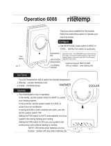
Get To Know Your Thermostat
Optional Wireless Module
Backlit, Scrolling Display
Backlit Cooler & Warmer
Buttons
Backlit LCD Display
Override Button
Heat or Cool
Demand Indicator
Red = Heat, Green = Cool
Setup Buttons Behind Door
Ambient Light Sensor

2
Get To Know Your Thermostat
Setup Buttons

3
Get To Know Your Thermostat
Display Features
1 The scrolling display will be used to help you easily navigate
the setup screens in the thermostat.
2 Clock with Day of the Week
Indicates the current time and day. This clock is also used to
program the time period schedules.
3 Mode Indicators
Selects the operational mode of the equipment.
HEAT - Indicates the heating mode.
COOL - Indicates the air conditioning mode.
HEAT & COOL - Indicates the system will automatically change-over
between heat and cool modes as the temperature varies.
OFF - Indicates heating and cooling is turned off.
4 Program icon
Indicates that Time Period Programming is running or is enabled
to be set.
5 Room Temperature Display
Indicates the current room temperature and displays the outdoor
temperature when selected.
6 Outdoor icon
Indicates the temperature displayed is from the optional
outdoor sensor.
HI
Lo
Program
Unoccupied123
ONOFF
Outdoor
Fan On
AUXHEAT
Override
Setup Step
2nd3rd
Stage
Am
Pm
18:88
188
188
88
188
1
3
3
5
6
2
4

4
Get To Know Your Thermostat
Display Features
7 Desired Set Temperature
Indicates desired room temperature(s). Also displays
the highest and lowest temperatures for the day.
8 Occupied & Unoccupied icons
When running the program, shows Occupied after start button
pressed, Unoccupied after program stop time
9 Wi-Fi icons
One dot indicates the thermostat recognizes the wireless module.
The “pull” icon indicates the thermostat is currently connected to
the Local access point, via the optional Wi-Fi Module.
10 Setup Step icon
Indicates the step number when the thermostat
is in the setup mode.
11 2nd and 3rd Stage icons
Indicates what stage of cooling or heating is currently energized.
12 icon
Indicates the keypad has been locked.
HI
Lo
Program
Unoccupied123
ONOFF
Outdoor
Fan On
A
UX
H
EAT
Override
Setup Step
2nd3rd
Stage
Am
Pm
18:88
188
188
88
188
7
12
7
9
10
11
8

5
Get To Know Your Thermostat
13 AuxHeat icon
Indicates 2nd stage electric strip heat is being used when the
thermostat is programmed for Heat Pump operation. Only the
Aux icon will appear during Cool to Dehumidify to indicate
Reheat operation.
14 Lo icon
Indicates the lowest recorded outdoor temperature for the day.*
15 Hi icon
Indicates the highest recorded outdoor temperature
for the day.*
16 Fan On icon
Indicates constant, continuous fan operation.
When Fan On is not lit - indicates the fan will only
operate when necessary to heat or to cool.
* Hi and Lo Temperatures for the day, reset at midnight.
HI
Lo
Program
Unoccupied123
ONOFF
Outdoor
Fan On
A
UX
H
EAT
Override
Setup Step
2nd3rd
Stage
Am
Pm
18:88
188
188
88
188
15
13
14
16
Display Features

6
Quick Start
During Setup and Programming:
Press the WARMER or COOLER buttons to modify the selection.
Press the MODE button to advance and confirm through the setup steps.
Setting the Clock and Day*
*Not available when wi-fi module is present
Press the SET CLOCK button. Adjust the clock using the WARMER or
COOLER buttons. Press MODE to advance to the day setting. Adjust
the day using the WARMER or COOLER buttons. Press the SET CLOCK
button to confirm settings.
TIP: To adjust the time by hours press and hold the FAN button while
pressing the WARMER or COOLER buttons.
Selecting the Heat or Cool Mode
Select mode by pressing the MODE button.
Heating Only - Only the heating operation will be controlled by the
thermostat in this mode.
Cooling Only - Only the cooling operation will be controlled by the
thermostat in this mode.
Heating or Cooling (Auto-Changeover) - AUTO will automatically select
heat or cool based on room temperature demand.
OFF - OFF indicates both heating and air conditioning systems are turned off.
WARMER
COOLER
MODE
Set
Clock
WARMER
COOLER
MODE
Set
Clock

7
Quick Start
Selecting your desired temperature
AUTO-CHANGEOVER MODE - Pressing the WARMER or COOLER buttons
in Auto mode will adjust both the heat and cool setpoints simultaneously.
To adjust heat and cool setpoints individually, choose HEAT mode to adjust
the heat setpoint and COOL mode to adjust the cool setpoint, then return to
AUTO mode.
HEAT OR COOL MODE - Pressing the WARMER or COOLER buttons in
Heat or Cool mode will adjust only the heat or cool setpoints individually
displayed.
Using the Fan Button
Fan On indicates constant fan operation. Fan On is not allowed when
the thermostat is in the OFF mode. Pressing the FAN button toggles
this feature. If you don’t see “Fan On”, the fan is in auto mode and will
only turn on during a heat or cool demand. The fan is forced into auto
mode when running the program and the thermostat shows “unoccupied”.
Using the Override/Start Button
The Override button (labeled Push To Start
on the door of the thermostat) has multiple
uses depending on the time of day when the button is pushed. One
unique feature of the T4900SCH is that when running a program, it will not
automatically bring in occupied setpoints at the designated start time. A single
press of this Override/Start button is needed within the occupied start/stop
times in order to bring in those comfort setpoints. This allows for variable start
times in each classroom with the actual starting event being a single press of
the Override/Start button, typically by the teacher prior to the start of the day.
This button has no effect unless the thermostat is running a program so the
following only applies when the program is On:
Outside of the preprogrammed Start/Stop times for the day: the thermostat
should be in Unoccupied. A single press of the Override/Start button will
temporarily bring in occupied setpoints for the amount of time specified
in Setup Step #58. Pressing the Override/Start button again will cancel the
override timer, returning the thermostat to unoccupied settings.
Within the Start/Stop times for the day: the thermostat should enter occupied
and bring in occupied setpoints for the rest of the day until the Stop time.
If the security settings allow, the setpoints may be adjusted for classroom
comfort.
FAN ON
AUTO
OUTDOOR
ACCSRY
HUMIDITY
OVERRIDE
NOTE: Override may only
be used when the thermostat
is set to PROGRAM ON.
(continued)

The thermostat should automatically return to unoccupied settings at the Stop
time. If the classroom is vacated early, pressing the Override/Start button for 5
seconds will bring in unoccupied settings immediately (and will show ‘OF’ for
the setpoints).
Note: During a programmed holiday, this button can only be used to override
to the occupied settings for the time specified in Setup Step #58. It is not
allowed to function as a start button since holiday settings take priority.
Override Hours (Setup Step 64)
Specifies how long the thermostat will allow occupied setpoints outside of
classroom hours. (0-6 hours). Note: if running a program and setup step #71
(light functions as start) is set to ON, turning lights on for at least 2 minutes
will bring in occupied setpoints for the rest of the day
Viewing the Temperature Sensors
OUTDOOR TEMP - Press the OUTDOOR button to view the current
outdoor temperature. The high and low temperatures for the day will also be
displayed. The high and low temperatures reset at 12:00 am. If connected to
a Skyport account, pressing outdoor button will show the temperatures for
your location if you don’t have a wired sensor connected. Press the OUTDOOR
button again to view any connected wired sensor (remote or SUPPLY).
Note: If no outdoor sensor is connected, and there isn’t outdoor temperature via
Wi-Fi, then 2 dashes [- -] will appear with the first button press.
REMOTE/SUPPLY TEMP - Press the Accessory Status button to
view linked wireless sensors and other accessories.
Press the Accessory Status button to return to the main screen.
Setup step #43 selects the use of the wired temperature sensor.
Viewing the Indoor Humidity Sensor
IMPORTANT: Allow at least 2 minutes after the thermostat is
powered on for the humidity to read correctly.
Press the HUMIDITY button then the mode button to display the current humidity
measured at the thermostat. The room’s relative humidity is displayed in the top
left corner. The humidification setpoint appears in the larger, center display and
can be adjusted using the WARMER or COOLER buttons. Press the MODE button
again to view and adjust the dehumidification setpoints. Press the HUMIDITY or
MODE button again to confirm settings and return to normal operation.
Note: Due to variations in environmental and equipment conditions, it is not
always possible to achieve the desired humidification or dehumidification
setpoint.
OUTDOOR
ACCSRY
HUMIDITY
OVERRIDE
OUTDOOR
ACCSRY
HUMIDITY
OVERRIDE
ACCESSORY
STATUS
8
Quick Start

9
Installation Instructions
Remove and Replace the old thermostat
To install the thermostat properly, please follow these step by step
instructions. If you are unsure about any of these steps, call a qualified
technician for assistance.
• Assemble tools: Flat blade screwdriver, wire cutters and wire
strippers.
• Make sure your Heater/Air Conditioner is working properly
before beginning installation of the thermostat.
• Carefully unpack the thermostat. Save the screws, any brackets,
and instructions.
• Turn off the power to the Heating/Air Conditioning system at
the main fuse panel. Most residential systems have a separate
breaker for disconnecting power to the furnace.
• Remove the cover of the old thermostat. If it does not come off
easily, check for screws.
• Loosen the screws holding the thermostat base or subbase to
the wall and lift away.
• If you have a smart phone handy, take a photo of the wiring for
future reference.
• Disconnect the wires from the old thermostat. Tape the ends of
the wires as you disconnect them, and mark them with the letter
of the terminal for easy reconnection to the new thermostat.
• Keep the old thermostat for reference purposes, until your new
thermostat is functioning properly.

10
Installation Instructions
Wire Connections
If the terminal designations on your old thermostat do not match those
on the new thermostat,
refer to the chart below or the wiring
diagrams that follow.
Wire from the Install on the
old thermostat Function new thermostat
terminal marked connector marked
G or F Fan G
Y1, Y Cooling Y1
W1, W Heating W1/0/B
Rh, R, M, Vr, A Power R
C Common C
O/B Rev. Valve W1/O/B*
W2 2nd Stage Heat W2
Y2 2nd Stage Cooling Y2
W3 3rd Stage Heat W3
H, Hum Humidity HUM
D, Dehum Dehumidity DEHUM
Ck1 Dry Contact Switch DRY CONTACT
CKGND Dry Contact Switch DRY CONTACT
* O/B is used if your system is a Heat Pump.

11
Installation Instructions
DRY
CONTACT
G
Y1
Y2
W3
R
W1/O/B
W2
HUM
DEHUM
C
AUX
REMOTE
SENSOR
OUTDOOR
SENSOR
The Explorer Thermostat Backplate
R 24 VAC return
G Fan relay
W1/O/B 1st stage heat circuit
W2 2nd stage heat circuit
Y1 1st stage compressor relay
Y2 2nd stage compressor relay
W3 3rd stage heat circuit
HUM Humidifier control circuit
DEHUM Dehumidifier control circuit
C 24 VAC common
AUX Aux output
OUTDOOR Outdoor sensor
SENSOR connections
REMOTE Remote sensor
SENSOR connections
DRY Dry Contact
CONTACT connections
IMPORTANT: This thermostat requires both R (24 VAC Return) and
C (24 VAC Common) be connected to the backplate terminals.
To remove the thermostat backplate:
Gently separate the display from
the base by pulling first from one
side, then the other until the two
pieces unsnap. A small screwdriver
may be used, very carefully, to start
seperating the two pieces.

12
Installation Instructions
Check Dip Switch
Ensure which switch is correct for your
system. Dip switches are located on the
back of the thermostat.
GAS/EL
HP
OR
GAS/EL HP
ON
1 2 3
ON
1 2 3
OR
O B BO
ON
1 2 3
ON
1 2 3
GAS ELEC
OR
GAS ELEC
ON
1 2 3
ON
1 2 3
1
GAS
O
GAS/EL
ELEC
B
HP
ON
23
1
GAS
O
GAS/EL
ELEC
B
HP
ON
23
1. When GAS/EL or HP is set for GAS/EL:
This switch (GAS or ELEC) controls how the
thermostat will control the Fan (G) terminal
in heating mode. When GAS is chosen, the
thermostat will not energize the Fan (G) terminal
in heating. When ELEC is chosen the thermostat
will energize the fan in heating.
2. When GAS/EL or HP is set for HP:
This switch (GAS or ELEC) defines the Aux Heat
type. When GAS is chosen, the auxiliary heat
will not be allowed to run during heat pump
operation. When ELEC is chosen, up to two
stages of auxiliary strip heat will be allowed to
run.
For Heat Pump Only
When the GAS/EL or HP dip switch is configured
for HP, this dip switch (O or B) must be set to
control the appropriate reversing valve. If O is
chosen, the W1/O/B terminal will energize in
cooling. If B is chosen, the W1/O/B terminal will
energize in heating.
This dip switch configures the thermostat to
control a conventional gas/electric system or a
heat pump. If your system is anything other than
a heat pump, leave this switch set for GAS/EL.

13
Installation Instructions
Sample Wiring Diagrams
Conventional Heating and Cooling Systems
Residential & Commercial 1 Stage Heating
with no Fan.
3 Wire, Heat Only
24VAC Power
24VAC Common
1st Stage Heat
Residential & Commercial 1 Stage Cooling.
4 Wire, Cool Only
R
C
Y1
G
Residential & Commercial 1 Stage Cooling,
with 1 stage Gas Heat.
5 Wire, 1 Stage Cooling, 1 Stage Heat
24VAC Power
24VAC Common
1st Stage Heat
1st Stage Cool
Fan
Residential & Commercial 1 Stage Cooling,
with 1 stage Electric Heat.
5 Wire, 1 Stage Cooling, 1 Stage Heat
24VAC Power
24VAC Common
1st Stage Heat
1st Stage Cool
Fan
Residential & Commercial 2 Stage Cooling,
with 3 stage Gas Heat.
8 Wire, 2 Stage Cooling, 3 Stage Heat
24VAC Power
24VAC Common
1st Stage Heat
2nd Stage Heat
3rd Stage Heat
1st Stage Cool
2nd Stage Cool
Fan
R
C
W1/O/B
Y1
G
R
C
W1/O/B
Y1
G
R
C
W1/O/B
W2
W3
Y1
Y2
G
R
C
W1/O/B
24VAC Power
24VAC Common
1st Stage Cool
Fan
1
GAS
O
GAS/EL
ELEC
B
HP
ON
23
1
GAS
O
GAS/EL
ELEC
B
HP
ON
23
1
GAS
O
GAS/EL
ELEC
B
HP
ON
23
1
GAS
O
GAS/EL
ELEC
B
HP
ON
23
1
GAS
O
GAS/EL
ELEC
B
HP
ON
23

14
Installation Instructions
Sample Wiring Diagrams
Heat Pump Systems
Residential & Commercial Heat Pump with
‘O’ Reversing Valve
5 Wire, 1 Stage Cooling, 1 Stage Heat
R 24VAC Power
C 24VAC Common
W1/O/B Reversing Valve
Y1 1st Stage Compressor
(Cool or Heat)
G Fan
Residential & Commercial Heat Pump with
‘O’ Reversing Valve.
8 Wire, 2 Stage Cooling, 4 Stage Heat
R 24VAC Power
C 24VAC Common
W1/O/B Reversing Valve
W2 3rd Stage Heat
W3 4th Stage Heat
Y1 1st Stage Compressor
(Cool or Heat)
Y2 2nd Stage Compressor
(Cool or Heat)
G Fan
Setup Step 24 is set to 2
(Number of Compressor Stages)
Residential & Commercial Heat Pump with
‘O’ Reversing Valve
6 Wire, 1 Stage Cooling, 2 Stage Heat
R 24VAC Power
C 24VAC Common
W1/O/B Reversing Valve
Y1 1st Stage Compressor
(Cool or Heat)
W2 Aux Heat
G Fan
Residential & Commercial Heat Pump with
‘O’ Reversing Valve.
7 Wire, 2 Stage Cooling, 3 Stage Heat
R 24VAC Power
C 24VAC Common
W1/O/B Reversing Valve
W2 3rd Stage Heat
Y1 1st Stage Compressor
(Cool or Heat)
Y2 2nd Stage Compressor
(Cool or Heat)
G Fan
Setup Step 24 is set to 2
(Number of Compressor Stages)
1
GAS
O
GAS/EL
ELEC
B
HP
ON
23
1
GAS
O
GAS/EL
ELEC
B
HP
ON
23
1
GAS
O
GAS/EL
ELEC
B
HP
ON
23
1
GAS
O
GAS/EL
ELEC
B
HP
ON
23

15
Installation Instructions
Sample Wiring Diagrams
Humidification or Dehumidification
G
Y1
Y2
W3
R
W1/O/B
W2
HUM
DEHUM
C
AUX
REMOTE
SENSOR
DRY
CONTACT
OUTDOOR
SENSOR
Humidification
System
DEHUM/
HUM
Dehumidification Terminal
on Equipment
Dry Contact and Aux Output
G
Y1
Y2
W3
R
W1/O/B
W2
HUM
DEHUM
C
AUX
REMOTE
SENSOR
DRY
CONTACT
OUTDOOR
SENSOR
12
11
10
9
8
7
6
5
4
3
2
1
Accessory control
such as a
Sprinkler System
Accessory such as a
Time Clock or door switch
/