Form: ORION-OE331-21-GPCPlusController-01A.doc Page 1 of 1
Description
The OE331-21 General Purpose Con-
troller Plus (GPC Plus) is used for con-
trolling equipment or processes that
cannot be controlled using HVAC con-
trollers. The Prism computer front end
software is used to interface with the
GPC Plus controller functions. The
GPC Plus Controller provides the flexi-
bility to control, schedule and/or monitor
equipment such as unit heaters, ex-
haust fans, motorized louvers, etc.. The
GPC Plus has (6) configurable inputs
which will accept signals from thermis-
tor temperature sensors, 4-20mA or 0-
5VDC transmitters or dry contact clo-
sures. An additional modular input is
provided for connection of an OE271
static pressure sensor. The GPC Plus
has (5) relay outputs for on/off control
and (2) analog outputs. With the addi-
tion of the OE352 2 Slot Expansion
Base Board and (1) OE357 4 Relay
Expansion Board, (4) additional relay
outputs are available providing for a
maximum of (9) usable relay outputs.
The GPC Plus also has (5) separate 2
event per day schedules, each with its
own optimal start functions built in. In
addition the GPC Plus provides lead/lag
start capabilities.
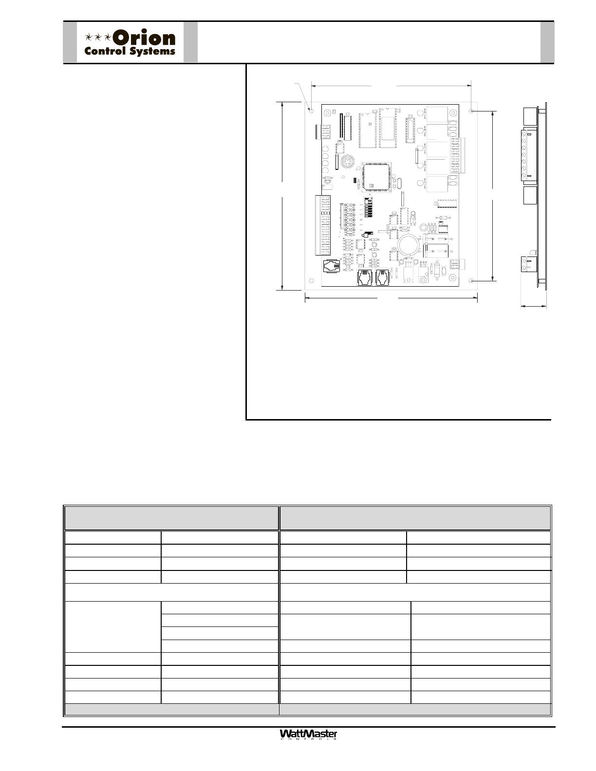
Mounting
The GPC Plus is provided with an integral backplate for mounting inside of a control enclosure. It is recom-
mended that the GPC Plus be mounted in the HVAC unit control enclosure, or in a control enclosure in the
building equipment room. An optional factory control enclosure for the GPC Plus is available.
OE331-21-GPC
GPC Plus Controller
Technical Data OE331-21-GPCPLUS
GPC Plus Controller
Power 24 Volt AC Weight 1.5 lb.
Power Consumption 8 VA Maximum Network Connection RS-485
Operating Temp
10°F to 149°F
Protocol HSI Open Protocol Token Passing
Operating Humidity 90% RH Non-Condensing Communications RS-485 - 9600 Baud
Inputs: Outputs:
Type III-10kohm sensors Total Relay Qty. On Board 5
4-20ma sensors
N.O. Binary Contact
Total Relay Qty. Available With
Optional Expansion Board
9
Types of Allowed
Inputs
N.C. Binary Contact Relay Power Rating (2 Amp @ 24 VAC)
Total Inputs Available 7 Analog Output Qty. 2
Static Pressure Inputs 1 (Modular ) Analog Output Signal 0-10 VDC
Configurable Inputs 6 Optimal Start Schedules (5) Total - (1) for Each Schedule
Schedules Available (5) 2 Event per day Lead Lag Scheduling (1) Output can be Configured
Three Year Warranty WattMaster reserves the right to change specifications without notice
RLY1
D1
D2D3D4D5
CX3
RAM
EPROM
C3
C2
U6
PHILIPS
CX6
C1
CX2
U2
U3
PAL
CX4
U4
TUC-5R PLUS
YS101816 REV. 2
V1
V2
V3
V5
V4
TB2
4
NETWORK
TOKEN
16
32
8
SW1
ADD
2
1
DDRESS
V6
POWER
GND
24VAC
L1
D16
R6
C9
SC1
R11
U11
MC34064A
D13
C16
9936
VR2
7824CT
M
TB4
R27
C13
R10
VR1
C19
C18
NE5090NPB3192
0PS
U8
CX8
U9
X1
R7
D10
R13
D12
C7
CX10
U10
CX12
U12
U14
CX14
PJ3
PJ2
PJ1
EXPANSION
PRESSURE
SENSOR
T'STAT
C17
D15
R26
C20
R25
R24
R22
U15
CX13
U13
C15
R19
R15
C14
D18
D17
PU1
PU2
PU3
PU4
PU5
PU7
D6
D7
D8
D9
D11
D14
C12
C10
0-5
VDC
0-1
VDC
JP1
C11
X2
GND
TB3
INPUTS
GND
GND
+VDC
AIN1
AIN2
AIN3
AIN4
AIN5
AOUT1
AOUT2
AIN7
RN4
1
RN5
RS-485
CX5
U5
R
TB1
SHLD
T
COMM
COMM
RN3
1
RN1
U1
CX1
1
LD6
COMM
PWR
LD7
LED1
LED2
LD9
LD8
R1
U7
RV1
VREF AD J
R28
+VREF
5.11V
TEST POINT
EWDOG
D19
RN2
1
COM1-3
COM4-5
R5
R4
R3
R2
R1
RLY2RLY3RLY4RLY5
CX15
(1 MEG)
HH
P1
C21
6.2“
6.6”
7.3”
6.7”
1.1”
.20 Dia.
Typ. of 4


