Page is loading ...

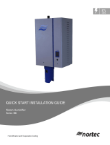
Quick Start Installation Guide
Gas
Combustion Air
Mounting
Plumbing
Electrical
Steam Distribution
NORTEC

Gas
Installation Requirements
1. Installation of piping must be in accordance with local codes,
and ANSI Z233.1, “National Fuel Gas Code,” in the United States
or CSA B149.1 installation codes in Canada.
2. In all installations, a certied manual shut o valve, located
outside the cabinet, must be installed. When black iron gas
pipe is used, a sediment trap must be located ahead of the
humidier gas controls.
3. Leak test all gas connections external to the humidier,
using a commercial soap solution made to detect leaks.
Bubbles indicate gas leakage. Seal all leaks before placing the
humidier in operation.
4. Do not use Teon tape on gas line pipe threads. A exible
sealant suitable for use with natural gas and propane gas is
recommended.
5. All gas piping should be adequately supported to prevent any
strain on inlet piping.
6. A 1/8” NPT plugged tapping, accessible for test gage
connection, must be installed immediately upstream of the
gas supply connection to the appliance.
* NOTE: Condair does not accept responsibility for
installation code violations.
Max & Min Gas Pressure
Inches w.c.
Gas Min Max
Natural 4.5 9.0
Propane 9.0 13.0
Gas Inlet Pipe Size
Nortec Model NPT
GS 100 1/2”
GS 200 3/4”
GS 300/400 1”
GS 500/600 1-1/4”

Combustion Air
General Requirements
1. Provide for adequate combustion and ventilation air in
accordance with sections 5.3, air for combustion and
ventilation, of the national fuel gas code, ANSI z223.1, or
sections 7.2, 7.3, 7.4 of CSA B149.1 installation codes, or
applicable provisions of the local building codes.
2. The required free area of supply air opening is:
13 in. Sq. (8,387 mm2), for Nortec GS 100
23 in. Sq. (14,839 mm2), for Nortec GS 200
35 in. Sq. (22,581 mm2), for Nortec GS 300
47 in. Sq. (30,323 mm2), for Nortec GS 400
59 in. Sq. (38,064 mm2), for Nortec GS 500
71 in. Sq. (45,806 mm2), for Nortec GS 600
3. Cabinet top and bottom contain air openings to provide
combustion air to the forced draft blower.
Do not block these openings.
4. Excessive exposure to contaminated combustion air will
result in safety and performance related problems. Known
contaminates include halogens, ammonia, and chlorides,
excessive dust, lime or dirt. Excessive exposure of electronics
to the contaminants will also result in performance related
problems. Contact Condair technical services if you have any
questions. If contaminants exist, isolate the unit from the
contaminated space.
5. Be sure to follow any local codes or regulations.
Sealed Combustion Guidelines
1. Installation of the combustion air supply line must be
carried out by adequately qualied personnel. All local
regulations relating to the provision of air supply systems
must be observed and adhered to.
2. The air supply line and the exhaust must individually not
exceed a respective equivalent length of 70 ft. (21 m). The
vent pipe diameter must be maintained over the overall
length of the vent.
3. The air supply line should be approximately as long as
the ue gas venting and must be supported at every 5
ft. (1.5 m) and additionally at every pipe bend. At low
temperatures, water condensation can form on the outside
of the pipe. To prevent this, it is recommended that the
supply air line is insulated and an in line heat is added.
Consult factory.
4. Attach the air supply line to the manifold using a hose
clamp or hose coupling if required. See Figure 6.
5. The air intake terminal and the ue gas terminal must end
at an outside location. See Figure 8: Location of air intake
and glue gas terminal must comply with all local and
national regulations.
WARNING
Air supply line should not obstruct any
services going to the humidifier front and
right side cabinet panels.
Refer to Nortec GS Venting Guide or
Installation Manual for information about
venting a Nortec GS unit.

Mounting
Mounting
Mount either oor mounted or on a Condair supplied mounting
stand.
1. Install on a level platform in an area with ambient temperature
41-104°F (5-40°C) and relative humidity 5- 80% (non-
condensing).
2. Ensure mounting surface is strong enough to support the
full weight of the humidier. If mounting using the optional
stand, assemble stand according to the provided instructions
and secure stand to the oor via the holes in the leg support
plates.
3. Install in location where the electrical power, the plumbing
connections, the gas supply and the vents can be connected.
* NOTE: The clearances above are for reference only and are
the minimum required for maintenance of the humidier.
4. Locate the humidier as close as possible to the steam
distributor location, net output will be reduced as a result
of heat loss through the steam line. The steam distributor
should be at least 36” (91 cm) above the humidier.
5. Avoid mounting humidier on combustible surfaces
including (but not limited to) carpet, tile, or certain
insulating materials.
6. Clearance dimensions shown are for reference only
and are the minimum required for maintenance of the
humidier. Consult local and national codes before nal
location and installation.
7. Be sure to follow any local codes or regulations.
Nortec GS
Model
Net/Full Weight – lbs (kg)
100 266/416 (120/180)
200 354/855 (160/266)
300 485/954 (217/432)
400 529/974 (239/441)
500 659/1340 (298/607)
600 703/1360 (318/616)

Plumbing
Water Supply
1. Supplied ll valve (½”NPT). Fill rate 10 l/min all unit sizes. Size
of piping is a minimum ½” copper; recommend ¾” up to
within 4 feet of unit.
2. Standard ll valves are sized for water pressure ranging from
30 to 80 psig (ideally 55 to 60 psig). This pressure should be
measured at the humidier if the water pressure is suspect.
3. Supply and install a shut o valve and union in the water
supply line dedicated to the humidier to facilitate servicing.
4. If water hammer occurs, install a shock arrester on the ll water
line just before the inlet to the ll valve. Water hammer will
damage the ll valve.
5. A 1” air gap is designed into the ll system of the Nortec
GS humidier. Some local plumbing codes may still require
the installation of a double check valve on the ll line to the
humidier to prevent contamination of the supply water
system. Verify with local codes and install if necessary.
6. Provide potable/softened/RO/DI water with the following
properties:
Conductivity: 0-1500 micro-Siemens
Hardness: 0-12 gpg
Alkalinity: 6.5-7.5 pH
Chloride: 0-40 ppm
Drain Line(s)
1. Use ¾”O.D. drain lines from the unit to the air gap.
2. The drain water line must be piped to an air gap within 3 ft (1
m) of the humidier.
3. The drain line should not end in a sink used frequently by
personnel, or where plumbing codes prohibit it.
4. Never install PVC piping as a drain line material. Always use
material suitable for with-standing 140ºF (60ºC).
5. Keep drain lines as short as possible. Keep drain lines sloped
down.
* NOTE: All water supply and drain line connections
should be installed in accordance with local plumbing
codes. Condair does not accept responsibility for
installation code violations.
,
I
r<

Electrical
WARNING
Wiring needs to be preformed by a
licensed Electrician.
Install Requirements
1. An external disconnect switch must be installed close to the
unit to allow for power interruption during servicing and/or
maintenance.
2. The humidier should only be connected to primary power
(main power) after all installation work has been completed.
3. Humidiers require eld wiring to primary voltage terminal
blocks. Depending on the unit, power requirement must be
120 Vac or 208-240 Vac, 15 A, 20 A or 30 A separately fused
circuit, single phase.
4. When installed, the appliance must be electrically grounded
Voltage (V) Rated Amps (A) Suggested Breaker (A)
GSTC/GSP 100 Indoor 120 2.1 15
208-240 1.1 15
GSTC/GSP 200 Indoor 120 3.7 15
208-240 1.9 15
GSTC/GSP 300 Indoor 120 5.3 15
208-240 2.7 15
GSTC/GSP 400 Indoor 120 6.8 15
208-240 3.5 15
GSTC/GSP 500 Indoor 120 8.4 15
208-240 4.3 15
GSTC/GSP 600 Indoor 120 10 15
208-240 5.2 15
GSTC Outdoor 100 120 6.3 15
208-240 3.2 15
GSTC Outdoor 200 120 7.4 15
208-240 15
GSTC Outdoor 300 120 13.7 20
208-240 6.9 15
GSTC Outdoor 400 120 15.2 20
208-240 7.7 15
GSTC Outdoor 500 120 21 30
208-240 10.6 15
GSTC Outdoor 600 120 22.6 30
208-240 11.5 15
Nortec Model
in accordance with local codes or, in the absence of local
codes, with the National Electrical Code, ANSI/NFPA
70, and/or the CSA C22.1 Electrical Code, if an external
electrical source is utilized.
5. All wiring is to be done in accordance with local and
national codes by a licensed electrician.

Steam Distribution
Install Requirements
1. The use of steam line other than copper, stainless steel tube or
Condair supplied steam line will void the warranty and may
adversely aect the operation of the humidier.
2. Steam lines must not have any restrictions which could allow
steam pressure to build in the tank.
3. The rst vertical 12 inches of steam line o the humidier must
not have any bends or turns.
4. Slope the steam line. If the slope is with the ow of steam,
then slope ½ inch for every horizontal run of 12 inches. If the
slope is against the ow of steam, then slope 2 inches for every
horizontal run of 12 inches.
5. Insulate the steam line with 1.0 inch (2.5 cm) pipe insulation
(minimum).
12 in. (30 cm)
min drop to
top of ‘P’ Trap
P Trap
min 8 in.
(20 cm)
plus duct
static pressure
Tee is same size
as steam line
Use a full size tee, not a 90
degree elbow for vertical
to horizontal transitions.
‘P’ Traps Use:
- 0.375 in condensate hose
- 1/4 in Med-L copper tubing, or
- 0.375 in stainless steel tubing
Condensate drains must be sloped down.
Route to humidifier fill cup if possible.
Steam Direction
Steam Direction
Steam Direction
2 in.
(5 cm)
1 ft (30 cm)
1ft (30 cm)
0.5 in.
(12 mm)
10 Degrees
2 Degrees
Minimal Slope (up)
Minimal Slope (down)
6. Support Steam line so weight is not on the unit.
7. Trap condensate at low points/elbows (Use full size ‘T’ for
traps).
8. Install a condensate trap every 15 feet / 4.5 meters of steam
line.
Nortec
Humidifier
Steam
output
[ lb ]
MED-L copper
tube nominal
steam line size
Stainless steel tube
diameter (wall
thickness 0.065”)
Steam loss per foot
in condensation
[ lb/ft ]
Steam line
maximum
equivalent length
GS 100 100 1-1/2” 1-3/4” 0.11 90 ft
GS 200 200 3” 3” 0.16 90 ft
GS 300 300 3” 3” 0.16 180 ft
GS 400 400 4” 4” 0.22 180 ft
GS 500 500 4” 4” 0.22 220 ft
GS 600 600 4” 4” 0.22 260 ft
Effective Lengths of Typical Steam-Line Fittings
Nominal tube
size
Standard
90°-elbow
Standard
45°-elbow
Side-outlet
tee
Gate valve* Globe valve*
1-1/2” 3.5 ft 1.75 ft 7 ft 0.8 ft 34 ft
1- 3/4” 3.5 ft 1.75 ft 7 ft 0.8 ft 34 ft
3” 5 ft 2.5 ft 11 ft 1.1 ft 54 ft
4” 8 ft 4 ft 15 ft 1.6 ft 80 ft
*Valve in full open position.
Steam Line Sizing
Use only stainless steel tube for reverse osmosis and
deionized water application.
Steam hose (Condair Supplied, part 1328820, 1 3/4”) can
be used for 100 lb/hr (45 kg/hr) applications. Use one
hose per 100 lb/hr (45 kg/hr) of output.

Printed in Canada
2576906-B
USA 826 Proctor Avenue, Ogdensburg, NY 13669
Canada 2740 Fenton Road, Ottawa, Ontario K1T 3T7
1.866.667.8321
na.info@condair.com
All information contained in this Quick Start Guide is for general
information purposes only. For complete Condair installation/
operation recommendations for your Condair equipment, please
refer to the installation manual for your specic system, accessories,
and components.
All electrical connections must be installed in accordance with local
and national electrical code requirements by a licensed electrician.
All water supply and drain line connections must be installed in
accordance with local plumbing codes by a licensed plumber.
Condair does not accept any liability for installations of humidity
equipment installed by unqualied personnel or the use of parts/
components/equipment that are not authorized or approved by
Condair.
/


