Shimano SL-RS25 Dealer's Manual

Type
Dealer's Manual

This manual is also suitable for

(English)
DM-SL0002-04
Dealer's Manual
ROAD MTB Trekking
City Touring/
Comfort Bike
URBAN SPORT E-BIKE
REVOSHIFT Shifter
SL-RV200
SL-RS47
SL-RS45
SL-RS36
SL-RS35
SL-RS34
SL-RS25
2
CONTENTS
CONTENTS .................................................................................2
IMPORTANT NOTICE ..................................................................3
TO ENSURE SAFETY ...................................................................4
LIST OF TOOLS TO BE USED ......................................................5
INSTALLATION/REMOVAL .........................................................6
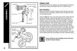
Installing the shifting lever ...................................................................6
ADJUSTMENT ............................................................................7
Left hand lever adjustment ...................................................................7
• Adjusting the position of the low side ................................................................................... 7
• Connection and securing of the inner cable .......................................................................... 9
• Adjusting the cable tension ................................................................................................... 11
• Adjusting the top side ............................................................................................................ 12
• Middle chainring adjustment ................................................................................................ 12
• Checking gear shifting and fine tuning ................................................................................ 14
Right hand lever adjustment ...............................................................15
• Adjusting the top side ............................................................................................................ 15
• Connection and securing of the inner cable ........................................................................ 16
• Adjusting the cable tension ................................................................................................... 17
• Low adjustment ...................................................................................................................... 17
• B-tension adjustment screw adjustment ............................................................................... 18
SIS adjustment ......................................................................................18
MAINTENANCE ........................................................................21
Replacing the inner cable ....................................................................21
• SL-RS47 / SL-RS45 / SL-RS36 / SL-RS35 / SL-RS34 / SL-RS25 ..................................................... 21
• SL-RV200.................................................................................................................................. 22
3
IMPORTANT NOTICE
IMPORTANT NOTICE
This dealer's manual is intended primarily for use by professional bicycle mechanics.
Users who are not professionally trained for bicycle assembly should not attempt to
install the components themselves using the dealer's manuals.
If any part of the information on the manual is unclear to you, do not proceed with the
installation. Instead, contact your place of purchase or a distributor for assistance.
Make sure to read all manuals included with the product.
Do not disassemble or modify the product other than as stated in the information
contained in this dealer's manual.
All manuals and technical documents are accessible online at https://si.shimano.com.
For consumers who do not have easy access to the internet, please contact a SHIMANO
distributor or any of the SHIMANO offices to obtain a hardcopy of the User's Manual.
Please observe the appropriate rules and regulations of the country, state or region in
which you conduct your business as a dealer.
For safety, be sure to read this dealer's manual thoroughly before use, and
follow it for correct use.
The following instructions must be observed at all times in order to prevent personal injury
and physical damage to equipment and surroundings.
The instructions are classified according to the degree of danger or damage which may occur
if the product is used incorrectly.
DANGER
Failure to follow the instructions will result in death or serious
injury.
WARNING
Failure to follow the instructions could result in death or
serious injury.
CAUTION
Failure to follow the instructions could cause personal injury or
physical damage to equipment and surroundings.
4
TO ENSURE SAFETY
TO ENSURE SAFETY
WARNING
Be sure to follow the instructions provided in the manuals when installing the product.
Only use SHIMANO genuine parts. If a component or replacement part is incorrectly
assembled or adjusted, it can lead to component failure and cause the rider to lose
control and crash.
Wear approved eye protection while performing maintenance tasks such as
replacing components.
NOTICE
Be sure to also inform users of the following:
Be sure to keep turning the crank during lever operation.
The gears should be periodically washed with a neutral detergent. In addition, cleaning
the chain with neutral detergent and lubricating it can be an effective way of extending
the life of the gears and the chain.
Products are not guaranteed against natural wear and deterioration from normal use
and aging.
For maximum performance we highly recommend SHIMANO lubricants and maintenance
products.
For installation to the bicycle, and maintenance:
When using a friction-supported front derailleur, use it with one of the following shifting
levers.
Shifting lever
SL-RV200-LN / SL-RS36-LN /
SL-RS35-LN / SL-RS34-LN /
SL-RS25-LN
SL-RV200-L / SL-RS47-L /
SL-RS45-L / SL-RS36-L / SL-
RS35-L
Front Derailleur
FD-TZ31 / FD-TZ30 / FD-TZ21 /
FD-TZ20
OK Not OK
The actual product may differ from the illustration because this manual is
intended mainly to explain the procedures for using the product.
5
LIST OF TOOLS TO BE USED
The following tools are needed for installation/removal, adjustment, and maintenance
purposes.
Tool
2.5 mm hexagon wrench
3 mm hexagon wrench
5 mm hexagon wrench
9 mm spanner
Cross head screwdriver
Cross head screwdriver [#1]
TL-CT12
6
INSTALLATION/REMOVAL
Installing the shifting lever
INSTALLATION/REMOVAL
Installing the shifting lever
1. Install the shifting lever in a position where it will not obstruct brake
operation.
Do not use a basket stay if it interferes with brake operation.
Leave a gap of 0.5 mm between the REVOSHIFT lever and the half grip. There is no need
to leave a gap for the SL-RV200.
Right hand leverLeft hand lever
2.5 - 3 N·m
(SL-RS25 / SL-RS35)
2 - 2.5 N·m
(SL-RS34 / SL-RS36 / SL-RS45 / SL-RS47)
1.5 - 2 N·m
(SL-RV200)
Half grip
Handlebar
Half grip
Handlebar
7
ADJUSTMENT
Left hand lever adjustment
ADJUSTMENT
Make sure to perform adjustment of the left hand lever / right hand lever in each indicated
order.
Left hand lever adjustment
Adjusting the position of the low side
1. For models equipped with it, remove the Pro-Set alignment block.
Pro-Set alignment block
2. Adjust the chain to the smallest chainring and the largest sprocket.
Largest sprocket Smallest chainring
8
ADJUSTMENT
Left hand lever adjustment
3. Adjust the low position of the chain guide.
Adjust the gap between the chain guide inner plate and chain to 0 - 0.5 mm.
Top swing type
Chain guide inner plate Chain
Down swing type
9
ADJUSTMENT
Left hand lever adjustment
Connection and securing of the inner cable
NOTICE
Insert the inner cable into the outer casing from the end with the marking on it.
In order to maintain cable operating efficiency, the end with the marking is greased.
Mark
When cutting the outer casing, cut the opposite end to the end with the marking.
After cutting, make the end round using a TL-CT12 needle or similar so that the inside
of the hole has a uniform diameter.
Coil not tipping over inward Coil tipping over inward
TL-CT12 needle
Attach the same outer end cap to the cut end of the outer casing.
Outer cap
10
ADJUSTMENT
Left hand lever adjustment
1. While firmly pulling the inner cable, tighten the wire mounting screw
to secure the cable in place.
FD-TY10 / FD-TX51 / FD-TX50
Top swing type
5 - 7 N·m
5 - 7 N·m
(FD-TY10)
(FD-TX51 / FD-TX50)
NOTICE
Route the inner cable as shown in the figure.
FD-TX51 FD-TX50
11
ADJUSTMENT
Left hand lever adjustment
FD-TZ31 / FD-TZ30
Normal type
10 N·m
Top route type
10 N·m
Adjusting the cable tension
1. After taking up the initial slack in the inner cable, re-secure to the front
derailleur.
Normal type
Pull
Pull
2. Cut off the excess length of inner cable and then install the inner end
cap.
12
ADJUSTMENT
Left hand lever adjustment
Adjusting the top side
1. Adjust the chain to the largest chainring and the smallest sprocket.
Smallest sprocket Largest chainring
2. Adjust the top position of the chain guide.
Adjust the gap between the chain guide inner plate and chain to 0 - 0.5 mm.
Top swing type
Down swing type
Chain guide inner plate Chain
Middle chainring adjustment
This adjustment is not necessary for LN (friction type) as it does not have a cable adjustment
barrel.
13
ADJUSTMENT
Left hand lever adjustment
1. Set the chain on to the largest sprocket, and at the front, move the
chain from the largest chainring to the middle chainring to adjust.
Largest sprocket Middle chainring
2. Adjust the middle chainring position of the chain guide.
Adjust the cable adjustment barrel so that the clearance between the chain guide inner
plate and the chain is 0 - 0.5 mm.
Cable adjustment barrel
0 - 0.5 mm
Chain guide inner plate
Chain
14
ADJUSTMENT
Left hand lever adjustment
Checking gear shifting and fine tuning
After completing all adjustment, move the shifting lever to check shifting. (This also applies if
shifting becomes difficult during use.)
Situation Adjustment method
If the chain falls to the crank side Turn the high limit screw clockwise.
If shifting is difficult from the middle chainring to
the largest chainring
Tighten the cable. If this does not improve the
situation, turn the high limit screw
counterclockwise.
If shifting is difficult from the middle chainring to
the smallest chainring
Turn the low limit screw counterclockwise.
If there is interference between the chain and the
front derailleur inner plate when the chain is on
the largest chainring
Turn the high limit screw clockwise.
If there is interference between the chain and the
front derailleur outer plate when the chain is on
the largest chainring
Tighten the cable. If this does not improve the
situation, turn the high limit screw
counterclockwise.
If the middle chainring is skipped when shifting
from the largest chainring
Tighten the cable.
If there is interference between the chain and front
derailleur inner plate when the chain is on the
largest sprocket at the rear and the middle
chainring
Loosen the cable.
If shifting is difficult from the largest chainring to
the middle chainring
If the chain falls to the bottom bracket side Turn the low limit screw clockwise.
15
ADJUSTMENT
Right hand lever adjustment
Adjusting the top side
1. Adjust by turning the high limit screw.
Adjust so that the center of the guide pulley is aligned with the outer line of smallest
sprocket when viewed from the rear side.
* The position of the high limit screw differs depending on the model.
High limit screw
Example
Outer line of smallest sprocket
Guide pulley
2. Install the chain.
16
ADJUSTMENT
Right hand lever adjustment
Connection and securing of the inner cable
NOTICE
Insert the inner cable into the outer casing from the end with the marking on it.
In order to maintain cable operating efficiency, the end with the marking is greased.
Mark
When cutting the outer casing, cut the opposite end to the end with the marking.
After cutting, make the end round using a TL-CT12 needle or similar so that the inside
of the hole has a uniform diameter.
Coil not tipping over inward Coil tipping over inward
TL-CT12 needle
Attach the same outer end cap to the cut end of the outer casing.
Outer cap
1. Secure the inner cable to the rear derailleur.
Be sure that the inner cable is securely in the groove.
5 - 7 N·m
Groove
17
ADJUSTMENT
Right hand lever adjustment
Adjusting the cable tension
1. After taking up the initial slack in the inner cable, re-secure to the rear
derailleur.
Pull
2. Cut off the excess length of inner cable and then install the inner end
cap.
Low adjustment
1. While turning the front chainwheel, operate the lever to shift to the
lowest gear.
2. Adjust by turning the low limit screw.
Adjust so that the center of the guide pulley is aligned with the center of the largest
sprocket.
* The position of the low limit screw differs depending on the model.
Low limit screw
Example
Guide pulley
Largest sprocket
18
ADJUSTMENT
SIS adjustment
B-tension adjustment screw adjustment
` RD-TX75 / RD-TX55 / RD-TX35
1. Set the chain on the largest sprocket and smallest chainring, and turn
the crank arm backward.
2. Turn the B-tension adjustment screw to adjust the guide pulley to be as
close to the gear as possible but not so close that it touches.
3. Set the chain on the smallest sprocket and repeat the above to make
sure that the chain tension is correct.
` RD-TZ50
1. In order to obtain suitable gear shifting performance, set the chain
onto the largest sprocket and the smallest chainring.
2. Turn the B-tension adjustment screw to adjust so that the distance
between the tip of the freewheel and the tip of the guide pulley is 10
mm.
B-tension adjustment
screw
Largest sprocket
Smallest sprocket
3. Set the chain on the smallest sprocket to make sure that the chain
tension is correct.
SIS adjustment
1. Operate the shifting lever once to move the chain from the smallest
sprocket to the 2nd sprocket.
19
ADJUSTMENT
SIS adjustment
2. While operating the lever just enough to close the gap in the lever,
turn the crank arm.
TECH TIPS
The best setting is when the shifting lever is operated just enough to close the
lever gap and the chain touches the 3rd sprocket counting from the smallest
sprocket and makes noise.
Gap
When shifting to the 3rd sprocket counting from the smallest sprocket
Tighten the adjustment screw until the chain returns to the 2nd sprocket counting from
the smallest sprocket. (Clockwise)
* The position of the adjustment screw differs depending on the model.
Adjustment screw
When no sound at all is generated
Loosen the screw until the chain touches the 3rd sprocket counting from the smallest
sprocket and makes noise. (Counterclockwise)
Adjustment screw
20
ADJUSTMENT
SIS adjustment
3. Return the lever to its original position (the position where the lever is
at the 2nd sprocket setting counting from the smallest sprocket and it
has been released) and then turn the crank arm.
If the chain is touching the 3rd sprocket counting from the smallest sprocket and making
noise, turn the adjustment screw clockwise slightly to tighten it just enough until the
noise stops.
4. Operate the lever to change gears, and check that no noise occurs in
any of the gear positions.
5. For the best SIS performance, periodically lubricate all power-
transmission parts.
  • Page 1 1
  • Page 2 2
  • Page 3 3
  • Page 4 4
  • Page 5 5
  • Page 6 6
  • Page 7 7
  • Page 8 8
  • Page 9 9
  • Page 10 10
  • Page 11 11
  • Page 12 12
  • Page 13 13
  • Page 14 14
  • Page 15 15
  • Page 16 16
  • Page 17 17
  • Page 18 18
  • Page 19 19
  • Page 20 20
  • Page 21 21
  • Page 22 22
  • Page 23 23
  • Page 24 24

Shimano SL-RS25 Dealer's Manual

Type
Dealer's Manual
This manual is also suitable for

Ask a question and I''ll find the answer in the document

Finding information in a document is now easier with AI