Hach Lange 2100AN Instrument Manual
- Category
- Measuring, testing & control
- Type
- Instrument Manual

47001-88
MODEL 2100AN
LABORATORY TURBIDIMETER
INSTRUMENT MANUAL
For Use With Software Version 1
© Hach Company, 1993-1997, 1999, 2000. All rights reserved. Printed in the U.S.A. 8/95 2ed
aa/dp Rev. 6, 2/00

2
TRADEMARKS OF HACH COMPANY
AccuGrow
AccuVac
AccuVer™
AccuVial™
®
®
®
®
®
®
®
®
®
®
®
®
®
®
®
®
®
®
2
2
®
®
®
®
®
®
Just Add Water™
®
®
®
®
®
®
®
®
®
®
®
®
®
®
®
™
®
®
®
®
®
®
®
®
®
WasteAway™
®
Add-A-Test™
AgriTrak™
AluVer
AmVer™
APA 6000™
AquaChek™
AquaTrend
BariVer
BODTrak™
BoroTrace™
BoroVer
C. Moore Green™
CA 610™
CalVer
ChromaVer
ColorQuik
CoolTrak
CuVer
CyaniVer
Digesdahl
DithiVer
Dr. F. Fluent™
Dr. H.Tueau™
DR/Check™
EC 310™
FerroMo
FerroVer
FerroZine
FilterTrak™ 660
Formula 2533™
Formula 2589™
Gelex
H O University™
H OU™
Hach Logo
Hach One
Hach Oval
Hach.com™
HachLink™
Hawkeye The Hach Guy™
HexaVer
HgEx™
HydraVer
ICE-PIC™
IncuTrol
LeadTrak
m-ColiBlue24
ManVer
MolyVer
Mug-O-Meter
NetSketcher™
NitraVer
NitriVer
NTrak
OASIS™
On Site Analysis.
ResultsYou Can Trust
OptiQuant™
OriFlow™
OxyVer™
PathoScreen™
PbEx
PermaChem
PhosVer
Pocket Colorimeter™
Pocket Pal™
PocketTurbidimeter™
Pond In Pillow™
PourRite™
PrepTab™
ProNetic™
Pump Colorimeter™
QuanTab
Rapid Liquid™
RapidSilver™
Ratio™
RoVer
™
Simply Accurate
SINGLET™
SofChek™
SoilSYS™
SP 510™
Spec ™
StablCal
StannaVer
SteriChek
StillVer
SulfaVer
Surface Scatter
TanniVer
TenSette
Test‘N Tube™
TestYES!
TitraStir
TitraVer
ToxTrak™
UniVer
VIScreen™
Voluette
ZincoVer
SM
SM
SM
sens
ion
√

3
TABLE OF CONTENTS
TRADEMARKS OF HACH COMPANY ....................................................................................................................... 2
SAFETY PRECAUTIONS .............................................................................................................................................. 7
OPERATION.................................................................................................................................................................9
SECTION 1 GENERAL DESCRIPTION........................................................................................................... 11
1.1 Instrument Description............................................................................................................................................. 11
1.2 Standard Accessories................................................................................................................................................ 11
1.3 Principle of Operation.............................................................................................................................................. 11
1.4 Preparation for Use................................................................................................................................................... 12
1.4.1 Unpacking....................................................................................................................................................... 12
1.4.2 Operating Environment................................................................................................................................... 13
1.4.3 Operating Power Selection ............................................................................................................................. 13
SECTION 2 TURBIDITY MEASUREMENT................................................................................................... 15
2.1 Operating Controls and Indicators ........................................................................................................................... 15
2.2 Measuring Turbidity................................................................................................................................................. 15
2.2.1 Nephelometric Measurement Procedure......................................................................................................... 16
2.2.2 Measurement Hints......................................................................................................................................... 17
2.3 Measurement Techniques......................................................................................................................................... 18
2.3.1 Cleaning Sample Cells.................................................................................................................................... 18
2.3.2 Applying Silicone Oil..................................................................................................................................... 18
2.3.3 Preparing Dilution Water................................................................................................................................ 19
2.3.4 Indexing and Matching Sample Cells............................................................................................................. 20
2.3.5 Removing Air Bubbles (Degassing)............................................................................................................... 23
2.3.6 Signal Averaging............................................................................................................................................. 25
2.3.7 Measuring Over-Range Samples.................................................................................................................... 26
2.3.8 Condensation (Fogging) ................................................................................................................................. 29
2.3.9 Calibration Check........................................................................................................................................... 29
2.3.10 Representative Sampling .............................................................................................................................. 30
SECTION 3 OPERATION...................................................................................................................................... 31
3.1 Operational Controls and Indicators ........................................................................................................................ 31
3.1.1 Using the
RANGE Key..................................................................................................................................... 33
3.1.2 Using the
UNITS/EXIT Key .............................................................................................................................. 33
3.1.3 Using the
SIGNAL AVG Key ............................................................................................................................ 34
3.1.4 Using the
FLOW Key....................................................................................................................................... 34
3.1.5 Using the
LINE FEED Key............................................................................................................................... 34
3.1.6 Using the
RATIO key....................................................................................................................................... 34
3.1.7 Using the
PRINT Key....................................................................................................................................... 35
3.1.8 Using the
CAL/ZERO Key................................................................................................................................ 35
3.1.9 Using the
ENTER Key..................................................................................................................................... 35
3.1.10 Using the Arrow Keys .................................................................................................................................. 35
3.1.11 Using the
SAMPLE Key................................................................................................................................. 36
3.1.12 Using the
SETUP Key ................................................................................................................................... 36
3.1.13 Key Annunciator Tone (Beeper)................................................................................................................... 36

4
TABLE OF CONTENTS, continued
3.2 Calibration ................................................................................................................................................................ 36
3.2.1 Formazin Stock Solution................................................................................................................................. 37
3.2.2 Dilution Water................................................................................................................................................. 37
3.2.3 Preparing Recommended Formazin Dilutions................................................................................................ 37
3.2.4 Calibrating the 2100AN (using Formazin Standards)..................................................................................... 39
3.2.5 Using Gelex
®
Secondary Turbidity Standards................................................................................................ 42
3.2.6 Formulating Formazin Stock Solution............................................................................................................ 43
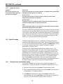
3.3 Special Research Applications.................................................................................................................................. 44
3.3.1 Ignoring Dilution Water .................................................................................................................................. 44
3.3.2 Editing Calibration Data Points....................................................................................................................... 44
3.3.3 Preparing Formazin Dilutions - User Selected................................................................................................ 45
3.3.4 Calibrating the 2100AN (user selected standards).......................................................................................... 45
SECTION 4 AIR PURGE SYSTEM..................................................................................................................... 47
4.1 Air Purge Connection ............................................................................................................................................... 47
SECTION 5 USING FLOW-CELL SYSTEM APPARATUS......................................................................... 49
5.1 Description................................................................................................................................................................ 49
5.2 Flow-Cell Kits (Low Pressure)................................................................................................................................. 50
5.2.1 Manual Flow-Cell Kit (Low Pressure)............................................................................................................ 51
5.2.2 Automated Flow-Cell Kit (Low Pressure) ...................................................................................................... 54
5.2.3 Tips for Flow-Cell Kits (Low Pressure).......................................................................................................... 59
5.2.4 High Pressure Flow-Cell Kit........................................................................................................................... 60
5.2.5 Flow-Cell Maintenance................................................................................................................................... 63
SECTION 6 DATA OUTPUT.................................................................................................................................. 65
6.1 Recorder Output........................................................................................................................................................ 65
6.1.1 Setting Recorder Minimum Value................................................................................................................... 65
6.1.2 Setting Recorder Maximum Value.................................................................................................................. 66
6.1.3 Setting Recorder Minimum Output................................................................................................................. 66
6.1.4 Setting Recorder Full-Scale Output................................................................................................................ 66
6.2 RS232 Connection.................................................................................................................................................... 67
6.3 Instrument Communication ...................................................................................................................................... 69
6.4 Printer........................................................................................................................................................................ 70
6.4.1 Built-In Printer ................................................................................................................................................ 70
6.4.2 Printer Setup Commands................................................................................................................................. 71
6.5 Using a Computer (RS232 Operating Commands) .................................................................................................. 72
SECTION 7 INSTRUMENT CLOCK.................................................................................................................. 75
7.1 Clock Description..................................................................................................................................................... 75
7.2 Setting Hours and Minutes ....................................................................................................................................... 75
7.3 Setting the Month and Day....................................................................................................................................... 75
7.4 Setting the Year......................................................................................................................................................... 75
7.5 Displaying Current Time .......................................................................................................................................... 75

TABLE OF CONTENTS, continued
5
SECTION 8 CELL ADAPTERS ........................................................................................................................... 77
8.1 Using Cell Adapters................................................................................................................................................. 77
8.1.1 Installing and Removing Cell Adapters.......................................................................................................... 77
SECTION 9 COLORIMETRIC MEASUREMENT........................................................................................ 79
9.1 Filter Modules.......................................................................................................................................................... 79
9.1.1 Installing Filter Assemblies............................................................................................................................ 79
9.1.2 Developing Applications Using Alternate Wavelengths ................................................................................ 80
9.2 Measurements in Color, % Transmittance and Absorbance .................................................................................... 80
9.2.1 Using Color Units (Platinum Cobalt Color Units Calibration Procedure)..................................................... 80
9.2.2 Tips for Color Measurement........................................................................................................................... 83
9.2.3 Using Transmittance Units (Transmittance 100% Procedure) ....................................................................... 83
9.2.4 Using Absorbance Units (Absorbance Zero Procedure) ................................................................................ 83
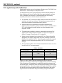
SECTION 10 APPLICATION SPECIFIC MEASUREMENTS.................................................................... 85
10.1 Application Specific Methods................................................................................................................................ 85
10.2 Application Specific Calibrations .......................................................................................................................... 86
10.2.1 Initial ASC Entry.......................................................................................................................................... 87
10.3 ASC Review........................................................................................................................................................... 89
10.4 Editing an ASC Point............................................................................................................................................. 89
10.5 Deleting a Single ASC Point.................................................................................................................................. 90
10.6 Deleting All ASC Points........................................................................................................................................ 90
INSTALLATION AND MAINTENANCE........................................................................................................... 91
SECTION 11 MAINTENANCE............................................................................................................................ 93
11.1 Cleaning ................................................................................................................................................................. 93
11.2 Lamp Replacement................................................................................................................................................. 93
SECTION 12 TROUBLESHOOTING................................................................................................................. 95
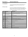
12.1 Introduction............................................................................................................................................................ 95
12.2 Error Codes ............................................................................................................................................................ 95
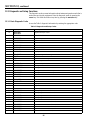
12.3 Diagnostic and Setup Functions............................................................................................................................. 96
12.3.1 Basic Diagnostic Codes................................................................................................................................ 96
12.3.2 Other Instrument Diagnostics....................................................................................................................... 98
SECTION 13 REPLACEMENT PARTS AND ACCESSORIES................................................................... 99
GENERAL INFORMATION................................................................................................................................101
HOW TO ORDER........................................................................................................................................................ 103
REPAIR SERVICE....................................................................................................................................................... 104
WARRANTY............................................................................................................................................................... 105

6


8

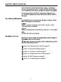
DANGER
Handling chemical samples, standards, and reagents can be dangerous. Review the necessary Material Safety
Data Sheets and become familiar with all safety procedures before handling any chemicals.
DANGER
La manipulation des échantillons chimiques, étalons et réactifs peut être dangereuse. Lire les Fiches de
Données de Sécurité des Produits (FDSP) et se familiariser avec toutes les procédures de sécurité avant de
manipuler tous les produits chimiques.
PELIGRO
La manipulación de muestras químicas, estándares y reactivos puede ser peligrosa. Revise las fichas
de seguridad de materiales y familiarícese con los procedimientos de seguridad antes de manipular
productos químicos.
GEFAHR
Das Arbeiten mit chemischen Proben, Standards und Reagenzien ist mit Gefahren verbunden. Es wird dem
Benutzer dieser Produkte empfohlen, sich vor der Arbeit mit sicheren Verfahrensweisen und dem richtigen
Gebrauch der Chemikalien vertraut zu machen und alle entsprechenden Materialsicherheitsdatenblätter
aufmerksam zu lesen.
PERIGO
A manipulação de amostras, padrões e reagentes químicos pode ser perigosa. Reveja a folha dos dados de
segurança do material e familiarize-se com todos os procedimentos de segurança antes de manipular
quaisquer produtos químicos.
9
OPERATION

10

11
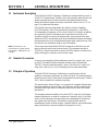
SECTION 1 GENERAL DESCRIPTION
1.1 Instrument Description
The Hach Model 2100AN Laboratory Turbidimeter measures turbidity from 0 to
10,000 NTU (Nephelometric Turbidity Units) with automatic range selection and
decimal point placement. Measure solutions with higher turbidity levels by
dilution with filtered sample and a simple calculation. Refer to Section 2.3.7 on
page 26 for additional information.
The 2100AN Laboratory Turbidimeter also displays in units of Nephelos
(0-67,000 Nephelos), EBCs (European Brewery Convention, 0-2,450 EBCs),
% Transmittance, Absorbance or Color Units (APHA Pt-Co Method). In addition,
two Application Specific Calibrations may be specified by the analyst. The
Application Specific mode uses the Nephelometric optical system in the same
manner as the NTU measurement mode. Special method development and sample
characterization also can be accomplished using the signal output from any of the
four detectors (see Instrument Setup for more information).
Note: Ratiomustbeonfor
measurement of samples greater
than 40 NTUs, 268 Nephelos and
9.8 EBCs.
The microprocessor-based Model 2100AN is designed for laboratory use, and
employs advanced optical and electronic design. The instrument operates on
115/230 Vac, and provides a built-in printer, an RS232 output for connection to a
printer, data logger or computer, and a recorder output.
1.2 Standard Accessories
Accessory items supplied with the turbidimeter include six sample cells, a set of
six Gelex
®
Secondary Turbidity Standards including a stray light standard,
7500-NTU Formazin Standard Ampule, a power cord, silicone oil, sample cell
oiling cloth, a dust cover, 2 rolls of printer paper and an instrument manual.
1.3 Principle of Operation
The Model 2100AN Laboratory Turbidimeter is a nephelometer with the
capability to measure in either Ratio on or Ratio off mode. The instrument meets
the design criteria of the United States Environmental Protection Agency (Method
181.1), and is acceptable for compliance reporting.
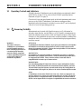
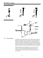
The optical system* (shown in Figure 1) is comprised of a tungsten-filament lamp,
lenses and apertures to focus the light, a 90° detector to monitor scattered light,
a forward-scatter light detector, a transmitted-light detector, and a back-scatter
light detector.
The instrument measures turbidity at less than 40 NTU using only the 90 degree
scattered-light detector or using the complete set of detectors (ratio). If the Ratio
mode is on, the instrument’s microprocessor uses a mathematical calculation to
ratio signals from each detector. The benefits of using the Ratio mode for
measurements include excellent linearity, calibration stability, wide measurement
range, and the ability to measure turbidity in the presence of color.
* U.S. patent 4,198,161.

12
SECTION 1, continued
Figure 1 Optical Diagram
1.4 Preparation for Use
1.4.1 Unpacking
Remove the instrument and accessories from their shipping box and inspect them
for damage that may have occurred during shipment due to rough handling or
extreme weather conditions. Verify the following items are present:
• Model 2100AN Laboratory Turbidimeter
• Instrument Manual
• 4000-NTU Formazin Standard, 100 mL
• 7500-NTU Formazin Standard Ampule
• Standardization Kit containing:
• Gelex Secondary Standards for Stray Light, 0-2, 0-20, 0-200, 200-4000 and
4,000-10,000 ranges
• 455 nm Filter Assembly
• USEPA Filter Assembly (installed in sample cell compartment
• Oiling Cloth
• Six Sample Cells
• Silicone Oil, 15 mL (0.5 oz.) SCDB*
• Power Cord
• Dust Cover
• 2 Rolls of Printer Paper
• Quick Reference Guide
Lamp Lens
Transmitted
Light
Detector
90°
DETECTOR
Forward
Scatter
Detector
Back Scatter
Detector
Sample Cell
* Self-Contained Dropping Bottle

SECTION 1, continued
13
If any of the items are missing or damaged, please contact the Customer
Service Department, Hach Company, Loveland, Colorado. Do not return the
instrument without prior authorization. In the United States, the toll-free number
is 1-800-227-4224. Outside the United States, contact your nearest Hach dealer.
1.4.2 Operating Environment
Use the turbidimeter in a clean, dust-free environment on a bench or table that is
free of vibration and that provides good air circulation around the instrument.
Keep the areas in the back and underneath of the instrument case free of materials
that could obstruct air flow through the vents.
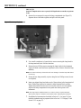
1.4.3 Operating Power Selection
The instrument is completely assembled when shipped from the factory except
for connecting the power cable to the chassis receptacle on the rear panel.
Voltage selection for 115 or 230 Vac is done automatically.
A power cord suitable for U.S. and Canadian 115 Vac line voltage is supplied with
the Model 2100AN (Cat. No. 47001-00). If this model is to be configured for
230 Vac, an approved UL/CSA power cord with NEMA 6-15P type cord cap must
be used in place of the 115V power cord supplied.
The Model 2100AN (Cat. No. 47001-02) is factory configured for European
230 Vac line voltage. The power cord supplied with this model is VDE approved,
and has a Continental European type plug.

14

15
SECTION 2 TURBIDITY MEASUREMENT
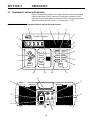
2.1 Operating Controls and Indicators
2100AN Laboratory Turbidimeter controls and indicators are explained in detail
in SECTION 3 on page 31. Also, refer to Model 2100AN operating features
illustrated in Figure 6 on page 31.
Close the cell cover and press the
I/O switch on the back instrument panel to turn
power on to the 2100AN Turbidimeter. Dark detector readings are taken
immediately after the instrument is switched on; error code E7 may be displayed
if the cell cover is left open during power up.
2.2 Measuring Turbidity
Measurements may be made with Signal Average on or off, with manual or
automatic range selection, and with Ratio on or off. Normally, measurements are
made with automatic range selection, Ratio and Signal Average on. When Signal
Averageison,theinstrument'smicroprocessorcompilesanumberofreadingsand
averages the result. The averaged value is calculated and displayed approximately
once every second.
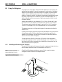
WARNING
The 2100AN Laboratory
Turbidimeter is not intended for
use with flammable samples or
those containing hydrocarbons or
concentrated acids that might
attack the 2100AN components.
Conduct compatibilitytests prior to
analysis if the sample to be
monitored is in question.
ATTENTION
Le turbidimètre de laboratoire 2100AN n’est pas prévu pour utilisation avec des liquides
inflammables ou contenant des hydrocarbures ou acides concentrés qui pourraient
attaquer les composants du 2100AN. Effectuer des essais préalables en cas de doute sur
la compatibilité de l’échantillon à contrôler.
ADVERTENCIA
El Turbidímetro de Laboratorio 2100AN no está diseñado para usarse con muestras
inflamables o que contengan hidrocarburos o ácidos concentrados que puedan atacar
los componentes del 2100AN. Ensaye antes del análisis si existe duda sobre la
compatibilidad de la muestra que se intenta analizar.
WARNHINWEIS
Das Labortrübungsmeßgerät 2100AN darf nicht zur Analyse entflammbarer Proben
oder Proben, die Kohlenwasserstoffe oder konzentrierte Säuren enthalten, welche die
Teile des 2100AN angreifen könnten, verwendet werden. Wenn die Verträglichkeit der
zu bestimmenden Probe fraglich ist, sollten vor der Analyse Tests durchgeführt werden.
AVISO
O Turbidímetro de Laboratório 2100AN não é feito com o fim de ser empregado com
amostras inflamáveis ou aquelas que contêm hidrocarbonetos ou ácidos concentrados
que possam atacar os componentes 2100AN. Os testes devem ser executados antes da
análise se existe alguma dúvida com respeito à compatibilidade da amostra a monitorar.

16
SECTION 2, continued
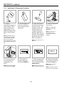
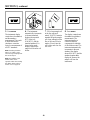
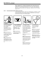
2.2.1 Nephelometric Measurement Procedure
1. Collect a
representative sample in a
clean container. Fill the
sample cell to the line
(approximately 30 mL).
Handle the sample cell by
the top. Cap the sample
cell.
Note: Instrument warm-up
stabilization time with Ratio
on is 30 minutes and with
Ratio off is 60 minutes.
Typical application is to leave
the instrument on 24 hours a
day.
2. Hold the sample cell
by the cap, and wipe to
remove water spots and
finger prints.
3. Apply a thin bead of
silicone oil from the top to
bottom of the cell—just
enough to coat the cell
with a thin layer of oil.
Using the oiling cloth
provided, spread the oil
uniformly. Then wipe off
theexcess. The cellshould
appear nearly dry with
little or no visible oil.
Note: See Section 2.3.2 on
page 18.
4. Install the appropriate
filter module.
Note: The USEPA filter
typicallyisusedforthis
application.
Note: Alternatively, an
860 nm filter can be
purchased for non-EPA
reporting.
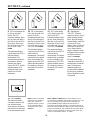
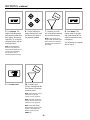
5. Place the sample cell
in the instrument cell
compartment, close
the lid.
Note: For immediate update
of the display, press
ENTER.
6. Select manual or
automatic ranging by
pressing the
RANGE key.
7. Select the appropriate
signal averaging setting
(onoroff)bypressingthe
SIGNAL AVG key.
Note: See Section 3.1.3 on
page 34 for more information.
8. Select the appropriate
Ratio setting (on or off) by
pressing the
RATIO key.
Note: Values > 40 NTU
require Ratio on.
Note: See Section 3.1.6 on
page 34 for more information.
RATIO

SECTION 2, continued
17
2.2.2 Measurement Hints
• Always cap the sample cell to prevent spillage of sample into the instrument.
• Always close the sample compartment lid during measurement.
• Install the appropriate Filter Assembly. The EPA Filter Assembly must be
installed for measurements requiring EPA reporting.
• Do not leave a sample cell in the cell compartment for extended periods
of time.
• Leave the instrument on 24 hours a day if the instrument is used regularly.
• Empty the cell compartment and turn off the power if the instrument is stored
for extended periods of time.
• Always use clean, scratch-free sample cells and caps.
• Always apply silicone oil.
• Always observe measurement techniques
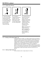
9. Select the appropriate
measurement unit (NTU,
EBC or NEPH) by
pressing the
UNITS/EXIT
key.
10. Read and record the
results.
Note: A time- and date-
stamped measurement
record can be printed or
transmitted by pressing the
PRINT key.

18
SECTION 2, continued
2.3 Measurement Techniques
Accurate and repeatable turbidity measurements depend on good,
consistent measurement techniques. Measurements are more accurate and
repeatable if close attention is paid to proper measurement techniques.
Four important considerations are:
• Use clean sample cells.
• Use sample cells in good condition.
• Remove air bubbles (degassing).
• Apply silicone oil to the sample cell.
Measure samples immediately to prevent changes in sample characteristics due to
temperature shifts and settling. Avoid dilution whenever possible; particles
suspended in the original sample may dissolve or otherwise change characteristics
when the temperature changes or the sample is diluted. Thus, the measurement
may not be representative of the original sample.
2.3.1 Cleaning Sample Cells
Cells must be meticulously clean and free from significant scratches. Glass
imperfections and superficial scratches from manufacturing are effectively
masked by the silicone oiling procedure outlined in Section 2.3.2. Clean the inside
and outside of the cells by washing thoroughly with a nonabrasive laboratory
detergent. Then continue cleaning with a 1:1 HCl bath followed by multiple rinses
with distilled or deionized water. Air dry the cells. Handle sample cells by the top
only to minimize dirt and fingerprints.
2.3.2 Applying Silicone Oil
Treat the outside of the cells with a thin coating of silicone oil to mask minor
imperfections and scratches that may contribute to light scattering. Use only Hach
silicone oil (Cat. No. 1269-36); it has the same refractive index as the sample cell
glass.
Apply a thin bead of silicone oil from the top to bottom of the cell- just enough
to coat the cell with a thin layer of oil. Using the oiling cloth provided, spread
the oil uniformly. Then, wipe off the excess so that only a thin coat of oil is left.
The cell should appear nearly dry with little or no visible oil. Avoid application
of excess oil that may attract dirt, and contaminate the sample compartment of
the instrument.

SECTION 2, continued
19
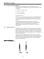
2.3.2.1 Silicone Oil Procedure
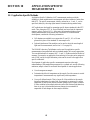
2.3.3 Preparing Dilution Water
Dilution water may be required for indexing and matching sample cells, diluting
over-range samples, and/or preparing Formazin Standards. Collect at least
1000 mL of high quality water (e.g., distilled, demineralized, or deionized water).
Check the turbidity of the dilution water before use. The 2100AN may be used to
check the dilution water turbidity because the instrument is precalibrated
at the factory. If the turbidity is greater than 0.5 NTU, the water may be filtered
with a 0.2 micron filter using the Sample Filtration and Degassing Kit
(Cat. No. 43975-10) or the equivalent. Clean all glassware with 1:1 hydrochloric
acid and rinse several times with dilution water when measuring low range
turbidity samples. Cap the cells to prevent small airborne particles from
contaminating the glassware if it is not used immediately.
1. Thoroughly clean and
rinse the sample cell.
Note: See Section 2.3.1.
2. Apply a thin bead of
silicone oil from the top to
bottom of the cell--just
enough to coat the cell
with a thin layer of oil.
Note: See Section 2.3.2.
3. Spread the oil
uniformly using the oiling
cloth provided. Then,
wipe off the excess so that
only a thin coat of oil is
left. The cell should
appear nearly dry with
little or no visible oil.
Note: Store the oiling clothin
a plastic storage bag to keep
the cloth clean.

20
SECTION 2, continued
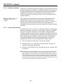
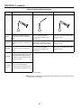
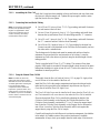
2.3.3.1 Dilution Water Filtration
2.3.4 Indexing and Matching Sample Cells.
Precise measurement of multiple, low-turbidity samples requires good laboratory
techniques to achieve accuracy and good repeatability. Matched sample cells are
required to minimize the effects of optical variation among cells. Alternatively,
a single sample cell used for every measurement minimizes reading variability
caused by cell to cell imperfections. Once cell orientation in the cell holder is
established, always use the alignment indicated on the cell, regardless of
sample-cell choice (refer to Section 2.3.4.1 on page 20 and/or Section 2.3.4.2 on
page 22). Using a single cell provides better accuracy and precision than matched
cells. A Flow-Cell System provides the best accuracy and reproducibility with the
added advantage of sample pour through convenience (see SECTION 5 on
page 49).
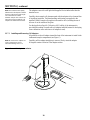
2.3.4.1 Indexing a Single Sample Cell
Add an orientation mark to a single sample-cell as follows:
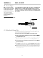
1. Attach the syringe to
the 3-way valve by gently
twisting the square end
into the syringe tip. Attach
the connector, tubing and
a 0.2 micron filter (clear
part faces syringe) as
shown. Be sure the
connections are tight.
2. Fill a beaker or
container with the waterto
be filtered. Insert the
tubing into the container.
Slowly draw the water
into the syringe by pulling
up on the syringe plunger.
3. Draw about 50 mL of
sample into the syringe.
Slowly push on the
plunger to force the water
through the filter and into
a graduated cylinder or
volumetric flask. Repeat
Steps2and3until
obtaining the desired
amount of water.
Note: Pushing water through
the filter becomes more
difficult as the filter clogs.
Discard a clogged filter and
attach a new filter when
necessary. Replacement
filters are available in
packages of 10 (Cat. No.
23238-10).
Page is loading ...
Page is loading ...
Page is loading ...
Page is loading ...
Page is loading ...
Page is loading ...
Page is loading ...
Page is loading ...
Page is loading ...
Page is loading ...
Page is loading ...
Page is loading ...
Page is loading ...
Page is loading ...
Page is loading ...
Page is loading ...
Page is loading ...
Page is loading ...
Page is loading ...
Page is loading ...
Page is loading ...
Page is loading ...
Page is loading ...
Page is loading ...
Page is loading ...
Page is loading ...
Page is loading ...
Page is loading ...
Page is loading ...
Page is loading ...
Page is loading ...
Page is loading ...
Page is loading ...
Page is loading ...
Page is loading ...
Page is loading ...
Page is loading ...
Page is loading ...
Page is loading ...
Page is loading ...
Page is loading ...
Page is loading ...
Page is loading ...
Page is loading ...
Page is loading ...
Page is loading ...
Page is loading ...
Page is loading ...
Page is loading ...
Page is loading ...
Page is loading ...
Page is loading ...
Page is loading ...
Page is loading ...
Page is loading ...
Page is loading ...
Page is loading ...
Page is loading ...
Page is loading ...
Page is loading ...
Page is loading ...
Page is loading ...
Page is loading ...
Page is loading ...
Page is loading ...
Page is loading ...
Page is loading ...
Page is loading ...
Page is loading ...
Page is loading ...
Page is loading ...
Page is loading ...
Page is loading ...
Page is loading ...
Page is loading ...
Page is loading ...
Page is loading ...
Page is loading ...
Page is loading ...
Page is loading ...
Page is loading ...
Page is loading ...
Page is loading ...
Page is loading ...
Page is loading ...
Page is loading ...
Page is loading ...
Page is loading ...
-
 1
1
-
 2
2
-
 3
3
-
 4
4
-
 5
5
-
 6
6
-
 7
7
-
 8
8
-
 9
9
-
 10
10
-
 11
11
-
 12
12
-
 13
13
-
 14
14
-
 15
15
-
 16
16
-
 17
17
-
 18
18
-
 19
19
-
 20
20
-
 21
21
-
 22
22
-
 23
23
-
 24
24
-
 25
25
-
 26
26
-
 27
27
-
 28
28
-
 29
29
-
 30
30
-
 31
31
-
 32
32
-
 33
33
-
 34
34
-
 35
35
-
 36
36
-
 37
37
-
 38
38
-
 39
39
-
 40
40
-
 41
41
-
 42
42
-
 43
43
-
 44
44
-
 45
45
-
 46
46
-
 47
47
-
 48
48
-
 49
49
-
 50
50
-
 51
51
-
 52
52
-
 53
53
-
 54
54
-
 55
55
-
 56
56
-
 57
57
-
 58
58
-
 59
59
-
 60
60
-
 61
61
-
 62
62
-
 63
63
-
 64
64
-
 65
65
-
 66
66
-
 67
67
-
 68
68
-
 69
69
-
 70
70
-
 71
71
-
 72
72
-
 73
73
-
 74
74
-
 75
75
-
 76
76
-
 77
77
-
 78
78
-
 79
79
-
 80
80
-
 81
81
-
 82
82
-
 83
83
-
 84
84
-
 85
85
-
 86
86
-
 87
87
-
 88
88
-
 89
89
-
 90
90
-
 91
91
-
 92
92
-
 93
93
-
 94
94
-
 95
95
-
 96
96
-
 97
97
-
 98
98
-
 99
99
-
 100
100
-
 101
101
-
 102
102
-
 103
103
-
 104
104
-
 105
105
-
 106
106
-
 107
107
-
 108
108


Hach Lange 2100AN Instrument Manual
- Category
- Measuring, testing & control
- Type
- Instrument Manual
Ask a question and I''ll find the answer in the document
Finding information in a document is now easier with AI
Related papers


Other documents
-
Apera TN400 User manual
-
 Bante Instruments TB200 Laboratory Turbidity Meter Owner's manual
-
BANTE TB100 User manual
-
Watts 22155 MICRO100 Lab Turbidimeter Owner's manual
-
 Lutron Electronics TU-2016 Operating instructions
-
 Bante Instruments TB100 Portable Turbidity Meter Owner's manual
-
wtw Turb 550 IR Operating instructions
-
 AMTAST TB200 Turbidity Meter User manual
-
CMA BT88i User guide
-
 Apera Instruments TN500 User manual


