Trane S*HK*90-130 W*HB Troubleshooting Manual
- Category
- Split-system air conditioners
- Type
- Troubleshooting Manual
This manual is also suitable for

SAFETY WARNING
Only qualified personnel should install and service the equipment. The installation, starting up, and
servicing of heating, ventilating, and air-conditioning equipment can be hazardous and requires specific
knowledge and training. Improperly installed, adjusted or altered equipment by an unqualified person could
result in death or serious injury. When working on the equipment, observe all precautions in the literature
and on the tags, stickers, and labels that are attached to the equipment.
November 2011 RT-SVP07B-EN
IntelliPak I models
S*HF*20-75 S*HL*20-75
S*HG*90-130 S*HK*90-130 W*HB, W*HE
IntelliPak II models
S*HJ090-162 W*HCA-C
Programming &
Troubleshooting
Guide
IntelliPak™ I and IntelliPak™ II
Commercial Single Zone Rooftop Air Conditioner or
Commercial Rooftop Air Handlers, with Variable Air
Volume (VVDA/VVZT) Controls or Constant Air
Volume (CVDA/CVZT) Controls

© 2011 Trane All rights reserved RT-SVP07B-EN
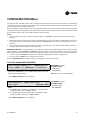
Warnings, Cautions and Notices
Warnings, Cautions and Notices. Note that warnings, cautions and notices appear at
appropriate intervals throughout this manual. Warnings are provide to alert installing contractors
to potential hazards that could result in death or personal injury. Cautions are designed to alert
personnel to hazardous situations that could result in personal injury, while notices indicate a
situation that could result in equipment or property-damage-only accidents.
Your personal safety and the proper operation of this machine depend upon the strict observance
of these precautions.
Read this manual thoroughly before operating or servicing this unit.
Important
Environmental Concerns!
Scientific research has shown that certain man-made chemicals can affect the earth’s naturally
occurring stratospheric ozone layer when released to the atmosphere. In particular, several of the
identified chemicals that may affect the ozone layer are refrigerants that contain Chlorine, Fluorine
and Carbon (CFCs) and those containing Hydrogen, Chlorine, Fluorine and Carbon (HCFCs). Not all
refrigerants containing these compounds have the same potential impact to the environment.
Trane advocates the responsible handling of all refrigerants-including industry replacements for
CFCs such as HCFCs and HFCs.
Responsible Refrigerant Practices!
Trane believes that responsible refrigerant practices are important to the environment, our
customers, and the air conditioning industry. All technicians who handle refrigerants must be
certified. The Federal Clean Air Act (Section 608) sets forth the requirements for handling,
reclaiming, recovering and recycling of certain refrigerants and the equipment that is used in these
service procedures. In addition, some states or municipalities may have additional requirements
that must also be adhered to for responsible management of refrigerants. Know the applicable
laws and follow them.
ATTENTION: Warnings, Cautions and Notices appear at appropriate sections throughout this
literature. Read these carefully:
WARNING
Indicates a potentially hazardous situation which, if not avoided, could result in
death or serious injury.
CAUTIONs
Indicates a potentially hazardous situation which, if not avoided, could result in
minor or moderate injury. It could also be used to alert against unsafe practices.
NOTICE:
Indicates a situation that could result in equipment or property-damage only
accidents
WARNING
Proper Field Wiring and Grounding Required!
All field wiring MUST be performed by qualified personnel. Improperly installed and grounded
field wiring poses FIRE and ELECTROCUTION hazards. To avoid these hazards, you MUST
follow requirements for field wiring installation and grounding as described in NEC and your
local/state electrical codes. Failure to follow code could result in death or serious injury.

RT-SVP07B-EN 3
Warnings, Cautions and Notices
WARNING
Personal Protective Equipment (PPE) Required!
Installing/servicing this unit could result in exposure to electrical, mechanical and chemical
hazards.
• Before installing/servicing this unit, technicians MUST put on all Personal Protective
Equipment (PPE) recommendedfor the work being undertaken. ALWAYS refer to appropriate
MSDS sheets and OSHA guidelines for proper PPE.
• When working with or around hazardous chemicals, ALWAYS refer to the appropriate MSDS
sheets and OSHA guidelines for information on allowable personal exposure levels, proper
respiratory protection and handling recommendations.
• If there is a risk of arc or flash, technicians MUST put on all Personal Protective Equipment
(PPE) in accordance with NFPA 70E or other country-specific requirements for arc flash
protection, PRIOR to servicing the unit.
Failure to follow recommendations could result in death or serious injury.

4 RT-SVP07B-EN
Table of Contents
Commonly Used Acronyms ............................................. 5
Glossary of Terms ................................................. 6
Menu Keys ....................................................... 11
Data Manipulation Keys ........................................... 12
Unit Operation Keys ................................................... 13
General Status Display ................................................. 13
STATUS Menu ........................................................ 26
SETUP Menu ..........................................................54
Emergency Override Definitions (with LCI or BCI module installed) ...... 66
SETPOINT Menu ...................................................... 85
CONFIGURATION Menu ................................................ 97
SERVICE MODE Menu (Local Human Interface only) ..................... 105
DIAGNOSTICS Menu ................................................. 113
Diagnostics ..................................................... 119
Module Input / Output Descriptions ................................ 144
Index ................................................................ 147

RT-SVP07B-EN 5
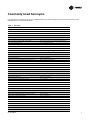
Commonly Used Acronyms
For convenience, a number of acronyms and abbreviations are used throughout this manual. These acronyms are
alphabetically listed and defined below.
Table 1. Acronyms
act = active, actuator IGV = inlet guide vanes
AH = air handler Indep = Independent
annunc = annunciate INFO = Information Only (Diagnostic)
AS = airside I/O = input/output
aux = auxiliary IOM = installation/operation/ maintenance manual
BAS = Building Automation System IPAK = IntelliPak I™, IntelliPak II™
BCI = BACnet
®
Communication Interface Module IPC = interprocessor communications
ccfm = cfm/100 (ex. 120.5 CCFM = 12050 CFM) IPCB = Interprocessor Communications Bridge (mod)
cfm = cubic-feet-per-minute iwc = inches water column
cfg = configured, configuration LCI = LonTalk
®
Communication Interface Module
ckt = circuit LCI-I = LonTalk
®
Communication Interface for IPAK
cmd = command LH = left-hand
comp(s) = compressor, compressors lo = low
cond(s) = condenser, condensers LON = LonWorks
®
(Echelon
®
, etc.)
config = configured, configuration LRE = leaving recovery exhaust
ctrl = control max = maximum
CV = constant volume manif = manifolded
CVDA = Const. Volume airflow/Discharge Air temp ctrl MCM = Multiple Circuit Module
CVZT = Const. Volume airflow/Zone Temp ctrl MDM = Modulating Dehumidification Module
cw = clockwise min = minimum, minute
cww = counterclockwise misc = miscellaneous
cy = cycle mod = modulating, module
DCV = Demand Control Ventilation MPM = Multi-Purpose Module
dflt = default MWU = morning warm-up
diag = diagnostic NSB = Night Setback Panel
dmpr = damper num = number
DWU = daytime warm-up O/A, OA = outside air
DX = direct expansion (compressor control) occ = occupied
E/A, EA = exhaust air OVRD = override
ECEM = Exhaust Comparative Enthalpy Module PAR = partial system disable, auto reset
econ = economizer, economizing PMR = partial system disable, manual reset
ent = entering pos = position
evap = evaporator O/A, OA = outside air
F/A, FA = fresh air pot = potentiometer
funct = function PPM = parts per million
GBAS = Generic Building Automation System (module) press = pressure
HEAT = heat, heater, Heat (module) prop = proportional
HGBP = hot gas bypass psig = pounds-per-square-inch gauge pressure
HGP = hot gas bypass PWS = part-winding start
hi = high R/A, RA = return air
HI = Human Interface (module) refrig = refrigerant
HO = History Only (Diagnostic) RHI = Remote Human Interface (module)
HVAC = heating, ventilation and air conditioning rpm = revolutions-per-minute
ICS = Integrated Comfort System RH = right-hand, relative humidity

6 RT-SVP07B-EN
Commonly Used Acronyms
Glossary of Terms
Carefully review these definitions since they are used throughout this document and the Installation, Operation,
Maintenance Guide (IOM). Knowledge of these terms is essential in gaining an understanding of how these units operate.
Active Setpoints. The setpoint which is currently being used by the specified control.
BACnet. An open, device networking communications protocol for controls. This protocol utilizes BACnet and ANSI/
ASHRAE
®
Standard 135-2004 protocol which provides building owners the capability to connect various types of building
control systems or subsystems together
Comparative Enthalpy. An economizer/cooling control strategy which compares return air enthalpy with outdoor
enthalpy. If the outdoor enthalpy is significantly less than return enthalpy the economizer will be utilized for cooling.
Compressor Protection Switch. (See Low Pressure Control). A pressure switch installed on the suction line that
prevents compressor operation below the switch’s setpoint. The purpose is to prevent no-flow scroll compressor
operation.
Comm3/4 . A Trane proprietary network communication protocol.
Comm5. Trane's implementation of LonTalk (an open network communication protocol).
Condenser Pressure. The saturated condenser pressure measured on each circuit's condenser section on
Evaporative Condenser units. Condenser pressure is converted to Saturated Condenser Temperature for display on the
Human Interface. The data from these sensors is used in head pressure control.
Control Band. The range of temperatures, pressures or humidity which would normally be maintained by the various
control functions.
Control Point. The value of a setpoint that an algorithm is using at any given time.
RHI = Remote Human Interface (module) temp = temperature
rpm = revolutions-per-minute UCM = unit control module
RT = rooftop unit unocc = unoccupied
RTM = rooftop module VAV = variable air volume
S/A, SA = supply air VCM = Ventilation Control Module
SAP = supply air pressure vdc = volts dc
sat = saturated vent = ventilation
SCM = Single Circuit Module vfd = variable frequency drive
SF = supply fan VOM = ventilation override module
src = source VVDA = Variable Volume airflow/Discharge Air temp ctrl
stg = stage VVZT = Variable Volume airflow/Zone Temp ctrl
stnd = standard w/ = with
stpt, stp = setpoint w.c. = water column
sw = switch wu = warm-up
sz = single-zone (unit airflow) XL = across-the-line start
TCI = Tracer Communications Interface (module)
Note:
1. Echelon, LON, LONWORKS, LonBuilder, NodeBuilder, LonManager, LonTalk, LonUsers,
Neuron, 3120, 3150, the Echelon logo, and the LonUsers logo are trademarks of Echelon
Corporation registered in the United States and other countries. LonLink, LonResponse,
LonSupport, LonMaker, and LonPoint are trademarks of Echelon Corporation.
2. BACnet
®
is a registered trademark of the American Society of Heating, Refrigeration and Air-
conditioning Engineers Inc. (ASHRAE.)
Table 1. Acronyms

RT-SVP07B-EN 7
Commonly Used Acronyms
Deadband. A narrow band of sensor range equally spaced above and below the setpoint that defines a region where
the algorithm will be satisfied and the controlled output will be maintained without change.
Dehumidification Override High Zone Temp. The temperature in the critical zone on VAV units where
Dehumidification is disabled to prevent over-heating the space due to excess reheat.
Dehumidification Override Low Zone Temp. The temperature in the critical zone on VAV units where
Dehumidification is disabled to prevent sub-cooling the space due to insufficient reheat.
Demand Control Ventilation (DCV). An ASHRAE compliant ventilation scheme that varies the Outside Air Damper
minimum position or Fresh Air Flow (TRAQs) between minimum and maximum ventilation Setpoints based on CO2 level.
Dry Bulb. An outdoor temperature above which economizing will be disabled (unless comparative enthalpy is the
economizer control type being used.)
Economizer Zone Temp Setpoint Suppression. A parameter used for setting the active economizer cooling control
point to a value lower than the Zone Temp Cooling Setpoint to optimize economizer operation.
Emergency Stop. A binary input on the RTM, connected to a field-supplied switch, when set to OPEN causes a unit
shutdown with a manual reset diagnostic.
Energy Recovery Wheel. A wheel that rotates through the outdoor and exhaust air streams, transferring energy
between the two, to optimize unit efficiency.
Evap Diff. Evaporator Differential is a parameter indicating performance of a refrigeration system. It is calculated by
determining the difference between the entering and leaving temperatures of the evaporator. If this value rises too high
it may indicate a problem with the system.
External Stop. A binary input on the RTM, connected to a field-supplied switch, when set to OPEN causes a unit stop
request.
Hot Gas Bypass. A feature to reduce a refrigeration circuit's cooling capacity by bypassing hot discharge line
refrigerant directly to the evaporator coil of the system to more effectively operate in low load conditions.
Humidification Control. During modes of continuous fan operation a relay is energized when the Humidity measured
in the controlled space drops below an adjustable Humidification Setpoint. The humidifier device is a user supplied device
placed in the supply air stream.
IntelliPak™ I. Units covering the 20 through 130 ton capacity IntelliPak cabinet sizes, and containing the latest control
modules and software.
IntelliPak™ II. Units covering the 90 through 150 ton capacity IntelliPak II cabinet sizes, and containing the latest control
modules and software.
LonTalk
®
. An open, device networking communications protocol for controls. This protocol is defined in ANSI approved
typical EIA/CEA-709.1-A-1999.
Low Ambient Compressor Lockout. A function which prevents compressor operation at low outdoor ambient
temperatures.
Night SetBack (NSB). Applies to the control of the rooftop unit during unoccupied periods. Also refers to the NSB
panel, a communicating wall sensor with night setback capability.
Rapid Restart. Certain unit applications require override of the normal unit startup sequence after a power outage.
Target cooling requirements are established within a specified time to meet extreme high return air temperatures.
Reference Enthalpy. An outdoor enthalpy value, set at the HI, above which economizing will be disabled.
Remote Human Interface. (See Interprocessor Communication Module). A human interface module designed
to be mounted remotely from the unit. There are some functional differences between a unit mounted and a remote
mounted human interface module.

8 RT-SVP07B-EN
Commonly Used Acronyms
Reset Amount Maximum. An adjustable parameter on the HI where the maximum amount of reset allowed is defined.
Reset End Temperature. The temperature at which the maximum reset amount will occur.
Reset Start Temperature. The temperature at which reset will begin.
Return Fan Control. . Return Fan Control is a feature which allows units to operate at a higher external or duct system
static pressure, or to reduce the load (horsepower requirement) on the supply fan motor. The fan is placed in the return
air path.
Return Fan Plenum Pressure. The area between the Exhaust and Return Dampers and the outlet of the Return Fan
defines the return plenum. The absolute static pressure measured in this area is the Return Fan Plenum Pressure.
Return Plenum Pressure High Limit. This control feature, available on all return fan options, shuts the supply fan and
return fan off if the pressure in the return plenum exceeds a non-adjustable setpoint of 3.5 iwc.
Space Pressure. The pressure in the building as measured by the space pressure transducer, referenced to outside
(atmospheric) pressure.
Single Zone Variable Air Volume. The active discharge air setpoint, used for cooling, heating and supply fan speed
control, is based on the zone temperature load conditions.
Supply Air Pressure High Limit. A pressure limit to prevent unit casing and/or ductwork over pressurization.
Statitrac™. A control method to maintain proper space pressurization.
Supply Air Pressure. The pressure in inches-water-column (IWC) of the supply duct plenum or outlet as measured by
the supply air pressure transducer, referenced to local outside (atmospheric) pressure.
Supply Air Tempering. An active heating mode where the supply air temperature has dropped below a preset value,
usually due to cold outside air being brought in to provide building ventilation.
Supply Air Temperature Control Point. The revised value of SA Temp Setpoint after supply air temperature reset has
been applied.
Supply Air Temperature Reset. A function that shifts the SA Temp Setpoint an amount based on the value of another
parameter—typically Zone Temp or Outdoor Air Temp. The purpose of this function is to lower unit capacity to better meet
load requirements.
Target Setpoints. An internally calculated control point which is typically derived from other setpoints in combination
with specific unit operating conditions.
UCM Control System
Trane Large Commercial Rooftop Units are controlled by a microelectronic control system that consists of a network of
modules and are referred to as Unit Control Modules (UCM).
The unit size, type VVDA (VAV w/ IGV/VFD), SZxx (SZVAV), RRXX (Rapid Restart), CVDA (VAV w/o IGV/VFD), CVZT (CV),
VVZT (SZVAV), heating functions, peripheral devices, options, exhaust capabilities, etc. determine the number and type
of modules that a particular rooftop unit may employ.
The UCM receives analog or binary inputs, then processes this information and supplies outputs in the form of
modulating voltages, contact closures, etc. to control damper actuators, fan motors, compressors, valves, electric heating
coils and other electrical devices in the unit to maintain set comfort levels.
The UCM provides some equipment protection functions both directly and indirectly, such as duct pressure limits and
compressor lockouts.
Listed below are the various modules that may be employed in a UCM control system.
Rooftop Module (1U1 IntelliPak II / 1U48 IntelliPak I)
(standard on all units) The RTM is the central processor of the system. It continuously receives information from the other
unit modules, sensors, the remote control panel, and customer supplied relays. It then interprets this information and

RT-SVP07B-EN 9
Commonly Used Acronyms
responds to cooling, heating, and ventilation requests by directing the other modules in the system to energize the proper
unit components. It also directly initiates supply and exhaust fan operations, and economizer operation.
Compressor Module (IU3 IntelliPak II / 1U49 IntelliPak I)
(compressor control, head pressure control, evaporative condensing) The SCM/MCM module upon receiving a request
for mechanical cooling staging from the RTM, energizes the appropriate compressors. It provides protection of the
refrigerant circuit through feedback information it receives from various protection devices. It provides the necessary
sensor interface to provide both air-cooled and water-cooled condenser head-pressure control.
Heat Module (1U6 IntelliPak II / 1U50 IntelliPak I)
(staged heat, modulating heat, air-handler chill water valve control) The HEAT module, directs the unit’s heater to stage
up, down, or modulate to bring the controlled temperature to within the applicable heating setpoint. Chill water valve
control is handled by the modulating output and is coordinated with the heat control to insure proper cooling and heating
operation.
Exhaust/Comparative Enthalpy Module (1U5 IntelliPak II / 1U52 IntelliPak I)
(Statitrac building pressure control, comparative enthalpy) The ECEM receives data from the return air humidity sensor,
the return air temperature sensor, and the return air space pressure transducer to control the economizer, exhaust fan and
the exhaust dampers to maintain set space pressure.
Ventilation Control Module (7U14 IntelliPak II / 3U218 IntelliPak I)
(TRAQ dampers, DCV, outdoor air preheat) The VCM receives data from two velocity pressure sensors associated with
front and back TRAQ assemblies to measure fresh air flow entering the unit. These measurements are converted to CFM
and added to give total fresh air flow. This value can be used for monitoring purposes, to maintain flow to a minimum
fresh air flow Setpoint, or to maintain appropriate CO2 levels in the controlled space using its space CO2 sensor input and
the DCV feature. Without TRAQ assemblies installed the VCM can use DCV and the CO2 sensor input to control OA Damper
minimum position to maintain CO2 levels in the space. A preheat control relay output is also provided on this module to
maintain tempered outdoor air during ventilation using the VCM Auxiliary Temperature input. The preheat unit is user-
supplied.
Multi Purpose Module (1U9 IntelliPak II / 1U105 IntelliPak I)
(return fan, energy recovery wheel, evaporative condensing) The MPM supports the function of return plenum pressure
control by providing inputs for measuring return plenum pressure, calibrating that reading, and providing an output to
control the return fan speed (if variable speed configured) in response to control algorithm requests. Energy Wheel control
along with bypass damper control, and interface to the saturated condensing pressure sensors for evaporative
condensing head-pressure control.
Modulating Dehumidification Module (1U15 IntelliPak II / 1U107 IntelliPak I)
(dehumidification hot gas reheat) The MDM supports specific control inputs and outputs for modulating dehumidification
control including modulating reheat and cooling valve control as well as the reheat pumpout coil relay output.
Generic Building Automation System Module (1U10 GBAS(0-5VDC) / 1U11 GBAS(0-10VDC)
IntelliPak II) or (1U51 – GBAS(0-5VDC)/(0-10VDC) IntelliPak I)
(interface to third party BAS controls) The GBAS modules allows a non-Trane building control system to communicate
with the unit and accepts external Setpoints in form of analog inputs (0 - 5 V or 0 - 10 V depending on the module selected)
and a binary Input for demand limit. Five (5) binary outputs are available on 0 - 5 V modules. One (1) binary output and
four (4) analog outputs are available on the 0 - 10 V modules. Refer to the “Field Installed Control Wiring” section of the
Unit Installation, Operation, Maintenance Manual (IOM) for the control wiring to the GBAS module and the various desired
Setpoints with the corresponding DC voltage inputs.
Ventilation Override Module (1U8 IntelliPak II / 1U53 IntelliPak I)
(special ventilation unit operation) The VOM module provides the necessary I/O interface to third party customer controls
and allows specific override operation of the unit’s air handling functions such as space pressurization, exhaust, purge,
unit off, etc.

10 RT-SVP07B-EN
Commonly Used Acronyms
Interprocessor Communications Bridge (1U12 IntelliPak II / 1U55 IntelliPak I)
(communications isolation for remote human interface, external IPC wiring) The IPCB module expands communications
from the unit UCM network to a Remote Human Interface Panel. DIP switch settings on the IPCB module for this application
should be; Switches 1 and 2 “Off”, Switch 3 “On”. This module is used to isolate the unit communications bus from the
outside wiring, and any potential wiring faults that may occur.
BACnet
®
Communication Interface Module (1U66 IntelliPak II / 1U104
IntelliPak I)
(used on units with Trane ICS or 3rd party Building Automation Systems) The BCI module expands communications from
the unit UCM network to a Trane Tracer Summit, or a 3rd party building automation system that utilizes BACnet, and allows
external Setpoint and configuration adjustment and monitoring of status and diagnostics.
Lontalk
®
Communication Interface Module (1U7 IntelliPak II / 1U65 IntelliPak I)
(used on units with Trane ICS or 3rd party Building Automation Systems) The LCI module expands communications from
the unit UCM network to a Trane Tracer Summit, or a 3rd party building automation system that utilizes LonTalk, and allows
external Setpoint and configuration adjustment and monitoring of status and diagnostics.
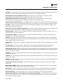
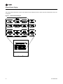
Human Interface Module (Local = 1U2, Remote = 9U13 IntelliPak II)
(1U65 IntelliPak I)
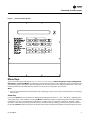
(standard on all units) The LHI and RHI (Local and Remote Human Interface) share a similar keypad which is illustrated,
see Figure 1. Human Interface Module" on page 11. This device enables the customer, building owner, or contractor, to
communicate to the Rooftop unit the necessary parameters for unit operation such as cooling and heating Setpoints,
demand limiting, ventilation override modes, etc
The local (unit mounted) Human Interface and the Remote Human Interface Panel functions are identical, except for
Service mode which is not available on the Remote Human Interface Panel.
The local HI Module is located in the unit’s main control panel. A small door located in the unit’s control panel door allows
access to the HI Module’s keypad and display window.
There is a 2 line by 40 character LCD screen which provides status information for the various unit functions as well as
menus used to set or modify the operating parameters. There is a 16 key keypad adjacent to the LCD screen, which allows
the operator to scroll through the various menus and make adjustments to the setpoints, etc.
The LCD screen has a backlight that makes the information easier to read. The light will go out if no keys are pressed for
30 minutes. If it goes out, simply press the Status key.
The information displayed in the LCD window will be top-level status information unless the operator initiates other
displays.
At power-up, the Human Interface LCD will display one of four initial screens illustrated in the “General Status” section.

RT-SVP07B-EN 11
Commonly Used Acronyms
Menu Keys
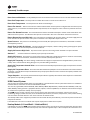
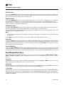
The six main menu keys illustrated in Figure 2. Human Interface Keypad,(Status, Setpoints, Setup, Configuration,
Diagnostics, and Service Mode) are used to bring up the various interactive menus where the user inputs and accesses
unit operating data. Pressing these keys will display the initial screen for the menu designated by the key’s name. The
following information describes the keys and their functions when viewing the various menus.
Note:
1. If no key is pressed for 30 minutes while the LCD is displaying a menu screen, it will revert back to the unit operating
status screen.
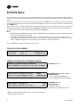
Status Key
Pressing the Status key causes the LCD to display the operating status screen; i.e. “On”, “Unit Stop”, “External Stop”,
“Emergency Stop”, “Service Mode”.Pressing the Next key allows the operator to scroll through the screens which provide
information such as air and refrigerant temperatures, humidity levels, fan operation, compressor operation, heater
operation, economizer positioning, exhaust operation, as well as heating, cooling, and compressor lockout setpoints.
Pressing the Status key while viewing any of the data screens will cause the LCD to go back to the operating status screen.
Figure 1. Human Interface Module

12 RT-SVP07B-EN
Commonly Used Acronyms
Setpoints Key
Pressing the Setpoints key will cause the LCD screen to display the first of the setpoint screens where the operator will
designate default temperature and pressure setpoints. While scrolling through the setpoint screens, pressing this key
again will cause the LCD to display the first setpoint screen.
Diagnostics Key
Pressing the Diagnostics key at any time will allow the operator to view any active unit diagnostics, or 20 of the most
recently logged unit diagnostics. The LCD screen will display one of the diagnostic screens (depending on which
diagnostic, if any, is present). If no key is pressed for 30 minutes while the screen is displaying diagnostic information,
it will revert back to the operating status display.
Configuration Key
Pressing the Configuration key will cause the LCD screen to display the first of the configuration screens where the
operator will designate unit configuration data such as unit type, capacity, system control, etc.
This information was programmed at the factory. Pressing the configuration key at any level in the configuration menu
will display the first configuration screen.
Note:
1. This key should be used if the unit’s configuration data is lost or new options are added in the field, and to view current
configuration.
2. The Stop key must be pressed prior to making any changes under the Configuration menu.
Setup Key
Pressing the Setup key will cause the LCD screen to display screens where the operator will designate various operating
parameters such as temperature and pressure ranges, limits, percentages, setpoint source selections, and sensor input
definitions for the control of the rooftop unit’s various operating modes. Pressing the Setup key at any level in the setup
menu will display the first setup screen.
Service Mode Key
Pressing the Service Mode key causes the LCD to display the first of the service test mode screens showing various unit
components which may be turned on or off for the particular test being performed. Once the status of these components
is designated, the LCD will display screens that allow the operator to designate the TEST START time delay for each test.
Data Manipulation Keys
The six data manipulation keys illustrated in Figure 2. Human Interface Keypad" on page 14, ( Enter, Cancel, + (Plus), -
(Minus), Previous, and Next are used to modify the data within the screens (change values, move the cursor, confirm
choices)
Enter Key
The Enter key will confirm the new values that were designated by pressing the + (Plus)or- (Minus) keys at all edit points.
When viewing status and diagnostics screens, it has no function.
Cancel Key
After changing data, at an editable screen, but before confirming it with the Enter key, pressing the Cancel key will return
the data to its previous value. This key shall also function to clear active diagnostics.
+ (Plus) Key
When viewing a setpoint screen, this key will increase the value of the displayed item per the units selected. When working
with a status menu, it will add the current status display to the CUSTOM MENU. When viewing setup, or service test
screens, it will proceed forward though all the selections of that menu item, increase setpoints, toggle choices OFF to ON,
DISABLED to ENABLED.

RT-SVP07B-EN 13
Unit Operation Keys
- (Minus) Key
When viewing a setpoint screen, this key will decrease the value of the displayed item per the units selected. When
working with a CUSTOM MENU, it will delete the current selected display. When viewing setup, or service test screens,
it will proceed backwards though all the selections of that menu item, decrease setpoints, toggle choices ON to OFF,
ENABLED to DISABLED.
Next Key
Pressing the Next key causes the LCD to scroll forward through the various displays for each menu. At displays with
multiple edit points it moves the cursor forward from one edit point to another.
Previous Key
Pressing the Previous key causes the LCD to scroll backward through the various displays for each menu. At displays with
multiple edit points, it moves the cursor backward from one edit point to another.
Unit Operation Keys
The four unit operation keys (Auto, Stop, Test Start, Custom) are used to control and monitor the unit in normal
operating mode, and also to initiate an active unit service test event.
Auto Key
Pressing the Auto key at any time will cause the display to go to the top level status display and, if the unit is shutdown,
will cause the unit to begin operation in the appropriate mode no matter what level in the menu structure is currently being
displayed. If the current display is an editable display, the Auto key will confirm the desired edit point similar to the Enter
key.
Stop Key
Pressing the Stop key will cause the unit to transition to the stop state. If the current display is editable, pressing the Stop
key will cancel the desired edit similar to the Cancel key. Prior to making any changes to the configuration menu screens,
the Stop key must be pressed.
Test Start Key (Service Test Mode Start)
Pressing the Test Start key while viewing any screen in the Service Mode Menu will start the service test. Pressing this
key while displaying any screen other than the Service Mode Menu will not start the service test, and has no other function.
Custom Key
Pressing the Custom key will change the display to the Custom Menu. This menu is simply a status menu that contains
screens that the user monitors most frequently. The custom menu can only contain five status screens. To create the
custom menu, press the Status key, followed by the Next key (this brings up the initial status screen). If you want to add
this screen to the custom menu, press the + (Plus) key, if not, press the Next key again until a status screen appears that
you would like to add to the custom menu. Pressing the + (Plus) key while viewing any of the various status screens will
add that screen to the custom menu. Once the custom menu is programmed it can be accessed by pressing the Custom
key. To remove a status screen from the custom menu, press the Custom key, then press the Next key until the status
screen that you want to remove appears, then press the - (Minus) key.
General Status Display
Anytime the rooftop unit is powered up, or the Status, Auto,orStop keys are pressed, the unit mounted Human Interface
will display one of the following general status display screens. The operator will then be able to enter keystrokes which
will allow him to navigate through a set of menus and submenus in order to provide/access various monitoring, setup,

14 RT-SVP07B-EN
General Status Display
and configuration information. The Human Interface will not display screens or parts of screens for which the unit is not
configured.
Figure 2. Human Interface Keypad

RT-SVP07B-EN 15
General Status Display
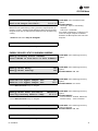
Unit “Off” or “Stopped”
If at power up the unit is not running, the following display will appear on the Human Interface LCD screen. When this
screen is being displayed, the only functional keys are the six menu keys (Status, Setpoints, Diagnostics, Setup,
Configuration, and Service Mode), the Auto key, the Custom key, and the Stop key.
Unit “On”
If the unit has entered an operating state (running), the following display will appear on the Human Interface LCD screen.
When this screen is being displayed, the only functional keys are the six menu keys (Status, Setpoints, Diagnostics,
Setup, Configuration, and Service Mode), the Auto key, the Custom key, and the Stop key.
Stop by Network Supply Fan ON
Initializing Diagnostics
Used With: Top Status Display
(Shown when unit is off or stopped)
Possible Values:
[see field descriptions at left]Top Left Field:
Unit Off
Unit Stopped
External Stop
Emergency Stop
Stop by Network
Unit Starting
Service Mode Off
Top Right Field:
Supply Fan OFF
Supply Fan ON
Bottom Left Field:
(blank)
Shutdown
Initializing
Freeze Avoidance
Active
Bottom Right Field:
(blank)
(Diagnostics)
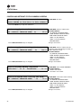
VVDA OA Flow 380.0 CCFM Supply Fan ON
Occupied Cool 2 Diagnostics
Used With: Top Status Display
(Shown when unit is on)
Possible Values:
[see field descriptions at left]Top Left Field:
CVZT
VVDA
CVDA
VVZT
Top Middle Field:
(blank)
OA Flow 0 to 500
CCFM
Freeze Avoidance
Top Right Field:
Supply Fan ON
Supply Fan OFF
Bottom Left Field:
(blank)
Occupied
Unoccupied
MorningWU
DaytimeWU
Standby
Shutdown
Occupied TOV
Initializing
Tempering
Rapid Restart
Bottom Middle Field:
(blank)
Heat 1 to 6
Cool 1 to 4
OA Dmpr 0 to 100 %
Dehumid
Purge
Humidify
SA Fan 0 to 100%
Bottom Right Field:
(blank)
Diagnostics

16 RT-SVP07B-EN
General Status Display
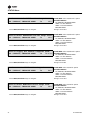
“Emergency Override” Active
If the unit has entered an Emergency Override mode of operation, one of the following displays will appear on the Human
Interface LCD screen.
“VOM” Active
If at power up the unit is running and has entered a Ventilation Override mode of operation, the following display will
appear on the Human Interface LCD screen.
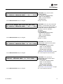
“No Configuration” Condition
If at power up the unit has not been programmed with the necessary configuration data for normal unit operation, the
following display will appear on the Human Interface LCD screen. When this screen is being displayed, the only functional
key is the Configuration key.
Note: This screen will only appear when the RTM has been field replaced. Refer to the Configuration Menu section.
Ventilation Override Mode
PRESSURIZE Diagnostics
Used With: LCI or BCI Options
Top Left Field:
Top Right Field: (blank)
Bottom Left Field:
PRESSUREIZE
DEPRESSURIZE
PURGE
SHUTDOWN
FIRE
Bottom Right Field:
Diagnostics (Trouble Indicator)
(blank)
Ventilation Override Mode A
Diagnostics
Used With: VOM Option
Possible Values:
Top Right Field: A, B, C, D, E, OFF
Bottom Left Field:
(blank)
Bottom Right Field:
Diagnostics (Trouble Indicator)
(blank)
NO CONFIGURATION PRESENT
PRESS CONFIGURATION KEY
Used With: All Units

RT-SVP07B-EN 17
General Status Display
Factory Presets
The UCM controlled unit has many operating functions which are preset at the factory, but may be modified to meet the
unique requirements of each job. The following list in Table 2, identifies each of the unit’s adjustable functions and the
value assigned to it. If these factory presets match the application’s requirements, simply press the Auto key at the Human
Interface module to begin unit operation (after completing the Pre-Start and Start-Up procedures in the Installation,
Operation, and Maintenance manual). If the application requires different settings, turn to the listed page beside the
function, press the designated function menu key, then press and hold the Next or Previous key until its screen appears
on the LCD. Once the proper screen appears, simply follow the programming instructions given below the applicable
screen in this manual.
Note: Listed items availability is dependent on unit configuration.)
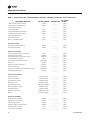
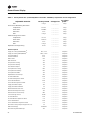
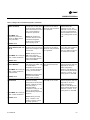
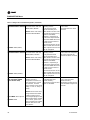
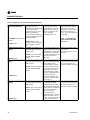
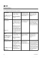
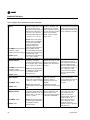
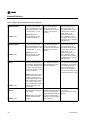
Table 2. Factory Presets List (Note: Listed Items availability is dependent on unit configuration.
Adjustable Function Factory Preset Changed To
To adjust
press...
General Function
Unit Address (Comm3/Comm4only) 1
___________ Setup
System Mode Auto ___________ Setup
Supply Fan Mode Auto ___________ Setup
Unit Start Delay 0 ___________ Setup
Single Zone VAV Econ Control Enabled ___________ Setup
Single Zone VAV Heat Control Disabled ___________ Setup
Daytime Warm-up Disabled ___________ Setup
Morning Warm-up Enabled ___________ Setup
Morning Warm-up type Cycling ___________ Setup
Supply Air Tempering Disabled ___________ Setup
Unoccupied Mechanical Cooling Enable ___________ Setup
Unoccupied Heating Enable ___________ Setup
Unoccupied Mechanical Cooling Enable ___________ Setup
Unoccupied Heating Enable ___________ Setup
Occupied Dehumidification Enable ___________ Setup
Unoccupied Dehumidification Enable ___________ Setup
Occupied Humidification Disable ___________ Setup
Unoccupied Humidification Disable ___________ Setup
Rapid Restart Economizer Control Disable ___________ Setup
VCM Preheat Output Disable ___________ Setup
Demand Limit Definition - Cooling None ___________ Setup
Demand Limit Definition - Heating None ___________ Setup
Compressor Lead/Lag Enable ___________ Setup
Evap Temperature Limit 35 F ___________ Setup
Coil Frost Cutout Temp 30 F ___________ Setup
Isolation Damper Interlock Disable ___________ Setup
Information Format
Display Text English ___________ Setup
Display Units English ___________ Setup
VAV Control
SA Temp Reset Cool None ___________ Setup

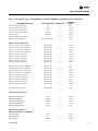
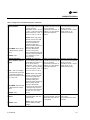
18 RT-SVP07B-EN
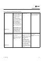
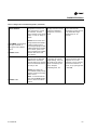
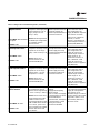
General Status Display
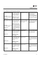
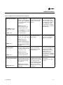
Reset Cool Start Temp (Zone/OA) (72/90) ___________ Setup
Reset Cool End Temp (Zone/OA) (69/70) ___________ Setup
Reset Cool Max Amount 5 ___________ Setup
SA Temp Reset Heat None ___________ Setup
Reset Heat Start Temp (Zone/OA) (65/10) ___________ Setup
Reset Heat End Temp (Zone/OA) (68/60) ___________ Setup
Reset Heat Max Amount 10 ___________ Setup
VAV Box Stroke Time 6 Min ___________ Setup
Max Occ. IGV/VFD Command 100 % ___________ Setup
Economizer Control
Economizer Control Enable Type Drybulb ___________ Setup
Unoccupied Economizer Enable ___________ Setup
Head Pressure Control
Sump Drain Relay Control (on power loss) Drain ___________ Setup
Sump Purge Interval Time Disabled ___________ Setup
Sump Purge Duration Time (IPak-I/IPak-II)
1
120/60 sec. ___________ Setup
Sump Water Heater Setpoint 38 F ___________ Setup
Low Limit (Air-cooled/Water-cooled)
1
80/70 deg F ___________ Setup
Upper Limit 120 deg F ___________ Setup
Temporary low limit suppression 20 deg F ___________ Setup
Efficiency check point 105 deg F ___________ Setup
Low amb. control point (Air-cooled/Water-cooled)
1
90/80 deg F ___________ Setup
Alternate Refrigerant Type
1
Disabled ___________ Setup
Sensor Source Selection
Daytime Warm-Up RTM Zone Temp ___________ Setup
Occupied Zone Control RTM Zone Temp ___________ Setup
Unoccupied Zone Control RTM Zone Temp ___________ Setup
Morning Warm-Up RTM Zone Temp ___________ Setup
Space Humidity Control RTM Space Humidity ___________ Setup
Dehumid OVRD Zone Temp RTM Zone Temp ___________ Setup
Zone Reset Function RTM Zone Temp ___________ Setup
Rapid Restart Function ECEM Return Temp ___________ Setup
Monitor RTM Zone Temp ___________ Setup
Outside Air Ventilation
Demand Control Ventilation Disable ___________ Setup
Active/Passive DCV Control Passive ___________ Setup
OA Flow Compensation Enabled ___________ Setup
OA Flow C02 Reset (IPak-INon-DCV) Disabled ___________ Setup
CO2 Start (IPak-I Non-DCV) 800 ___________ Setup
CO2 Max (IPak-I Non-DCV) 1000 ___________ Setup
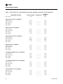
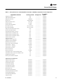
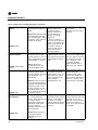
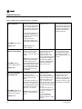
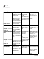
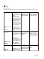
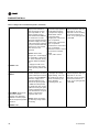
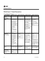
Table 2. Factory Presets List (continued)(Note: Listed Items availability is dependent on unit configuration.
Adjustable Function Factory Preset Changed To
To adjust
press...

RT-SVP07B-EN 19
General Status Display
OA Flow Calibration Gain (Left) 1.0 ___________ Setup
OA Flow Calibration Offset (Left) 0 CFM ___________ Setup
OA Flow Calibration Gain (Right) 1.0 ___________ Setup
OA Flow Calibration Offset (Right) 0 CFM ___________ Setup
OA Normalization 100 CCFM ___________ Setup
OA Flow Calibration Data - Altitude: 0 Ft ___________ Setup
RTM Alarm Output Definition Any Active Diagnostic ___________ Setup
GBAS Input/Output Definitions
GBAS (0-5) Analog Input 1 Definitions Not Assigned ___________ Setup
GBAS (0-5) Analog Input 2 Definitions Not Assigned ___________ Setup
GBAS (0-5) Analog Input 3 Definitions Not Assigned ___________ Setup
GBAS (0-5) Analog Input 4 Definitions Not Assigned ___________ Setup
GBAS (0-5) Output 1 Definitions Not Assigned ___________ Setup
GBAS (0-5) Output 2 Definitions Not Assigned ___________ Setup
GBAS (0-5) Output 3 Definitions Not Assigned ___________ Setup
GBAS (0-5) Output 4 Definitions Not Assigned ___________ Setup
GBAS (0-5) Output 5 Definitions Not Assigned ___________ Setup
GBAS (0-10) Analog Input 1 Definitions Not Assigned ___________ Setup
GBAS (0-10) Analog Input 2 Definitions Not Assigned ___________ Setup
GBAS (0-10) Analog Input 3 Definitions Not Assigned ___________ Setup
GBAS (0-10) Analog Input 4 Definitions Not Assigned ___________ Setup
GBAS (0-10) Output 1 Definitions Not Assigned ___________ Setup
GBAS (0-10) Output 2 Definitions Not Assigned ___________ Setup
GBAS (0-10) Output 3 Definitions Not Assigned ___________ Setup
GBAS (0-10) Output 4 Definitions Not Assigned ___________ Setup
GBAS (0-10) Output 5 Definitions Not Assigned ___________ Setup
Ventilation Override Definition See Definitions ___________ Setup
Temperature Input Offset for...
RTM Zone Temperature
0 deg F ___________ Setup
RTM Aux Temperature
0 deg F ___________ Setup
Outdoor Air Temperature
0 deg F ___________ Setup
Heat Aux Temperature
0 deg F ___________ Setup
Return Air Temperature
0 deg F ___________ Setup
Device Characteristics…
Outside Air Damper (if equipped)
Actuator Setup
Direct ___________ Setup
Max Stroke Time
30 sec ___________ Setup
Max Voltage
10 VDC ___________ Setup
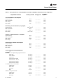
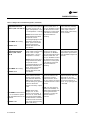
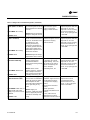
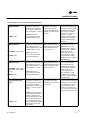
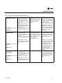
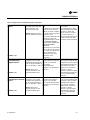
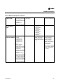
Table 2. Factory Presets List (continued)(Note: Listed Items availability is dependent on unit configuration.
Adjustable Function Factory Preset Changed To
To adjust
press...

20 RT-SVP07B-EN
General Status Display
Min Voltage
2 VDC ___________ Setup
Supply Fan IGV/VFD (if equipped)
Actuator Setup
Direct ___________ Setup
Max Stroke Time
30/0 sec ___________ Setup
Max Voltage
10 VDC ___________ Setup
Min Voltage
2 VDC ___________ Setup
Return Fan VFD (if equipped)
Actuator Setup
Direct ___________ Setup
Max Stroke Time
60/0 sec ___________ Setup
Max Voltage
10 VDC ___________ Setup
Min Voltage
2 VDC ___________ Setup
Exhaust Damper/VFD (if equipped)
Actuator Setup
Direct ___________ Setup
Max Stroke Time
60 sec ___________ Setup
Max Voltage
10 VDC ___________ Setup
Min Voltage
0 VDC ___________ Setup
Hydronic Heat (if equipped)
Actuator Setup
Direct ___________ Setup
Max Stroke Time
60 sec ___________ Setup
Max Voltage
10 VDC ___________ Setup
Min Voltage
2 VDC ___________ Setup
Low Ambient Damper Ckt-1 (if equipped)
Actuator Setup
Direct ___________ Setup
Max Stroke Time
60 sec ___________ Setup
Max Voltage
10 VDC ___________ Setup
Min Voltage
2 VDC ___________ Setup
Low Ambient Damper Ckt-2 (if equipped)
Actuator Setup
Direct ___________ Setup
Max Stroke Time
60 sec ___________ Setup
Max Voltage
10 VDC ___________ Setup
Min Voltage
2 VDC ___________ Setup
Cond Fan VFD Ckt -1(if equipped)
Actuator Setup
Direct ___________ Setup
Max Stroke Time
60 sec ___________ Setup
Max Voltage
10 VDC ___________ Setup
Min Voltage
0 VDC ___________ Setup
Table 2. Factory Presets List (continued)(Note: Listed Items availability is dependent on unit configuration.
Adjustable Function Factory Preset Changed To
To adjust
press...
Page is loading ...
Page is loading ...
Page is loading ...
Page is loading ...
Page is loading ...
Page is loading ...
Page is loading ...
Page is loading ...
Page is loading ...
Page is loading ...
Page is loading ...
Page is loading ...
Page is loading ...
Page is loading ...
Page is loading ...
Page is loading ...
Page is loading ...
Page is loading ...
Page is loading ...
Page is loading ...
Page is loading ...
Page is loading ...
Page is loading ...
Page is loading ...
Page is loading ...
Page is loading ...
Page is loading ...
Page is loading ...
Page is loading ...
Page is loading ...
Page is loading ...
Page is loading ...
Page is loading ...
Page is loading ...
Page is loading ...
Page is loading ...
Page is loading ...
Page is loading ...
Page is loading ...
Page is loading ...
Page is loading ...
Page is loading ...
Page is loading ...
Page is loading ...
Page is loading ...
Page is loading ...
Page is loading ...
Page is loading ...
Page is loading ...
Page is loading ...
Page is loading ...
Page is loading ...
Page is loading ...
Page is loading ...
Page is loading ...
Page is loading ...
Page is loading ...
Page is loading ...
Page is loading ...
Page is loading ...
Page is loading ...
Page is loading ...
Page is loading ...
Page is loading ...
Page is loading ...
Page is loading ...
Page is loading ...
Page is loading ...
Page is loading ...
Page is loading ...
Page is loading ...
Page is loading ...
Page is loading ...
Page is loading ...
Page is loading ...
Page is loading ...
Page is loading ...
Page is loading ...
Page is loading ...
Page is loading ...
Page is loading ...
Page is loading ...
Page is loading ...
Page is loading ...
Page is loading ...
Page is loading ...
Page is loading ...
Page is loading ...
Page is loading ...
Page is loading ...
Page is loading ...
Page is loading ...
Page is loading ...
Page is loading ...
Page is loading ...
Page is loading ...
Page is loading ...
Page is loading ...
Page is loading ...
Page is loading ...
Page is loading ...
Page is loading ...
Page is loading ...
Page is loading ...
Page is loading ...
Page is loading ...
Page is loading ...
Page is loading ...
Page is loading ...
Page is loading ...
Page is loading ...
Page is loading ...
Page is loading ...
Page is loading ...
Page is loading ...
Page is loading ...
Page is loading ...
Page is loading ...
Page is loading ...
Page is loading ...
Page is loading ...
Page is loading ...
Page is loading ...
Page is loading ...
Page is loading ...
Page is loading ...
Page is loading ...
Page is loading ...
Page is loading ...
Page is loading ...
-
 1
1
-
 2
2
-
 3
3
-
 4
4
-
 5
5
-
 6
6
-
 7
7
-
 8
8
-
 9
9
-
 10
10
-
 11
11
-
 12
12
-
 13
13
-
 14
14
-
 15
15
-
 16
16
-
 17
17
-
 18
18
-
 19
19
-
 20
20
-
 21
21
-
 22
22
-
 23
23
-
 24
24
-
 25
25
-
 26
26
-
 27
27
-
 28
28
-
 29
29
-
 30
30
-
 31
31
-
 32
32
-
 33
33
-
 34
34
-
 35
35
-
 36
36
-
 37
37
-
 38
38
-
 39
39
-
 40
40
-
 41
41
-
 42
42
-
 43
43
-
 44
44
-
 45
45
-
 46
46
-
 47
47
-
 48
48
-
 49
49
-
 50
50
-
 51
51
-
 52
52
-
 53
53
-
 54
54
-
 55
55
-
 56
56
-
 57
57
-
 58
58
-
 59
59
-
 60
60
-
 61
61
-
 62
62
-
 63
63
-
 64
64
-
 65
65
-
 66
66
-
 67
67
-
 68
68
-
 69
69
-
 70
70
-
 71
71
-
 72
72
-
 73
73
-
 74
74
-
 75
75
-
 76
76
-
 77
77
-
 78
78
-
 79
79
-
 80
80
-
 81
81
-
 82
82
-
 83
83
-
 84
84
-
 85
85
-
 86
86
-
 87
87
-
 88
88
-
 89
89
-
 90
90
-
 91
91
-
 92
92
-
 93
93
-
 94
94
-
 95
95
-
 96
96
-
 97
97
-
 98
98
-
 99
99
-
 100
100
-
 101
101
-
 102
102
-
 103
103
-
 104
104
-
 105
105
-
 106
106
-
 107
107
-
 108
108
-
 109
109
-
 110
110
-
 111
111
-
 112
112
-
 113
113
-
 114
114
-
 115
115
-
 116
116
-
 117
117
-
 118
118
-
 119
119
-
 120
120
-
 121
121
-
 122
122
-
 123
123
-
 124
124
-
 125
125
-
 126
126
-
 127
127
-
 128
128
-
 129
129
-
 130
130
-
 131
131
-
 132
132
-
 133
133
-
 134
134
-
 135
135
-
 136
136
-
 137
137
-
 138
138
-
 139
139
-
 140
140
-
 141
141
-
 142
142
-
 143
143
-
 144
144
-
 145
145
-
 146
146
-
 147
147
-
 148
148
-
 149
149
-
 150
150


Trane S*HK*90-130 W*HB Troubleshooting Manual
- Category
- Split-system air conditioners
- Type
- Troubleshooting Manual
- This manual is also suitable for
Ask a question and I''ll find the answer in the document
Finding information in a document is now easier with AI
Related papers
-
Trane IntelliPak Programming, Troubleshooting Manual
-
-
Trane IntelliPak Signature SCRF-029 Programming Manual
-
-
-
-
Trane IntelliPak SIRG-020 User manual
-
-
-
Trane IntelliPak Signature SCWF-038 Installation, Owner, And Diagnostic Manual
Other documents
-
Greenheck 484279 Microprocessor Controller DOAS v4.001 February 2020 Operating instructions
-
Extron electronic CVDA 6 MX Dual User manual
-
-
-
-
-
-
-
-