CPCI-CAN/331
CompactPCI CAN Interface
CPCI-CAN/331-2
Hardware Installation
and
Technical Data
to Product C.2027.02, C.2027.04, C.2027.05
CPCI-CAN/331 Hardware Manual • Doc. No.: C.2027.21 / Rev. 2.2 Page 1 of 37
esd electronic system design gmbh
Vahrenwalder Str. 207 • 30165 Hannover • Germany
http://www.esd.eu
Phone: +49 (0) 511 3 72 98-0 • Fax: +49 (0) 511 3 72 98-68

N O T E
The information in this document has been carefully checked and is believed to be entirely reliable.
esd makes no warranty of any kind with regard to the material in this document, and assumes no
responsibility for any errors that may appear in this document. In particular descriptions and
technical data specified in this document may not be constituted to be guaranteed product features
in any legal sense.
esd reserves the right to make changes without notice to this, or any of its products, to improve
reliability, performance or design.
All rights to this documentation are reserved by esd. Distribution to third parties, and reproduction
of this document in any form, whole or in part, are subject to esd's written approval.
© 2015 esd electronic system design gmbh, Hannover
esd electronic system design gmbh
Vahrenwalder Str. 207
30165 Hannover
Germany
Phone: +49-511-372 98-0
Fax: +49-511-372 98-68
E-Mail: [email protected]
Internet: www.esd.eu
This manual contains important information and instructions on safe and efficient
handling of the CPCI-CAN/331. Carefully read this manual before commencing any work
and follow the instructions.
The manual is a product component, please retain it for future use.
Trademark Notices
CompactPCI® is a registered trademark of the PCI Industrial Computers Manufacturers Group.
CANopen® and CiA® are registered community trademarks of CAN in Automation e.V.
Windows is a registered trademark of Microsoft Corporation in the United States and other countries.
The PICMG® name and logo are registered trademarks of the PCI Industrial Computer Manufacturers Group.
All other trademarks, product names, company names or company logos used in this manual are reserved by their
respective owners.
Page 2 of 37 Hardware Manual • Doc. No.: C.2027.21 / Rev. 2.2 CPCI-CAN/331

Document file: I:\Texte\Doku\MANUALS\CPCI\CAN-331\Englisch\CPCI-CAN331_Hardware_en_22.odt
Date of print: 2015-12-07
Document type
number: DOC0800
Hardware version: CAN-CPCI/331 Rev. 1.0
CAN-CPCI/331 Rev. 1.1
Document History
The changes in the document listed below affect changes in the hardware as well as changes in
the description of the facts, only.
Rev. Chapter Changes versus previous version Date
2.2
- Safety Instructions and classification inserted
2015-12-07
2. Chapter completely revised
3.3 DeviceNet option deleted
3.4 Chapter updated
5.2 Note inserted
6. Chapter “DeviceNet Option” deleted
7. CAN wiring hints for double twisted pair cables
9. New chapter: “Declaration of Conformity”
10. Chapter “Order Information” moved and revised
Technical details are subject to change without further notice.
CPCI-CAN/331 Hardware Manual • Doc. No.: C.2027.21 / Rev. 2.2 Page 3 of 37

Classification of Warning Messages and Safety Instructions
This manual contains noticeable descriptions, warning messages and safety instructions, which
you must follow to avoid personal injuries or death and property damage.
This is the safety alert symbol.
It is used to alert you to potential personal injury hazards. Obey all safety messages
and instructions that follow this symbol to avoid possible injury or death.
DANGER, WARNING, CAUTION
Depending on the hazard level the signal words DANGER, WARNING or CAUTION are used to
highlight safety instructions and warning messages. These messages may also include a warning
relating to property damage.
DANGER
Danger statements indicate a hazardous situation which, if not avoided, will result in
death or serious injury.
WARNING
Warning statements indicate a hazardous situation that, if not avoided, could result in
death or serious injury.
CAUTION
Caution statements indicate a hazardous situation that, if not avoided, could result in
minor or moderate injury.
NOTICE
Notice statements are used to notify people on hazards that could result in things other than
personal injury, like property damage.
NOTICE
This NOTICE statement indicates that the device contains components sensitive to
electrostatic discharge.
NOTICE
This NOTICE statement contains the general mandatory sign and gives information that
must be heeded and complied with for a safe use.
INFORMATION
INFORMATION
Notes to point out something important or useful.
Page 4 of 37 Hardware Manual • Doc. No.: C.2027.21 / Rev. 2.2 CPCI-CAN/331

Safety Instructions
● When working with the CPCI-CAN/331 follow the instructions below and read the manual
carefully to protect yourself from injury and the CPCI-CAN/331 from damage.
● The device is a built-in component. It is essential to ensure that the device is mounted in a way
that cannot lead to endangering or injury of persons or damage to objects.
● Do not use damaged or defective cables to connect the CPCI-CAN/331 and follow the CAN
wiring hints in chapter: "Correct Wiring of Electrically Isolated CAN Networks".
● In case of damages to the device, which might affect safety, appropriate and immediate
measures must be taken, that exclude an endangerment of persons and domestic animals and
property.
● Current circuits which are connected to the device have to be sufficiently protected against
hazardous voltage (SELV according to EN 60950-1).
● The CPCI-CAN/331 may only be driven by power supply current circuits, that are contact
protected. A power supply, that provides a safety extra-low voltage (SELV) according to
EN 60950-1, complies with this conditions.
● The device has to be securely installed in the control cabinet before commissioning.
● Protect the CPCI-CAN/331 from dust, moisture and steam.
● Protect the CPCI-CAN/331 from shocks and vibrations.
● The CPCI-CAN/331 may become warm during normal use. Always allow adequate ventilation
around the CPCI-CAN/331 and use care when handling.
● Do not operate the CPCI-CAN/331 adjacent to heat sources and do not expose it to
unnecessary thermal radiation. Ensure an ambient temperature as specified in the technical
data.
DANGER
Hazardous Voltage - Risk of electric shock due to unintentional contact with
uninsulated live parts with high voltages inside of the system into which the CPCI-
CAN/331 is to be integrated.
→ Disconnect all hazardous voltages (mains voltage) before opening the system.
→ Ensure the absence of voltage before starting any electrical work
NOTICE
Electrostatic discharges may cause damage to electronic components.
To avoid this, perform the steps described on page 11 before you touch the CPCI-
CAN/331, in order to discharge the static electricity from your body.
Qualified Personal
This documentation is directed exclusively towards personal qualified in control and automation
engineering.
The installation and commissioning of the product may only be carried out by qualified personal,
which is authorized to put devices, systems and electric circuits into operation according to the
applicable national standards of safety engineering.
Conformity
The CPCI-CAN/331-2 meets the demands of the EU regulations and EMC standards printed in the
conformity declaration at the end of this manual.
CPCI-CAN/331 Hardware Manual • Doc. No.: C.2027.21 / Rev. 2.2 Page 5 of 37

Intended Use
The intended use of the CPCI-CAN/331 is the operation as CAN interface board for the
CompactPCI bus.
The guarantee given by esd does not cover damages which result from improper use, usage not in
accordance with regulations or disregard of safety instructions and warnings.
●The CPCI-CAN/331 is intended for installation in a CompactPCI system.
● The operation of the CPCI-CAN/331 in hazardous areas, or areas exposed to potentially
explosive materials is not permitted.
● The operation of the CPCI-CAN/331 for medical purposes is prohibited.
Service Note
The CPCI-CAN/331 does not contain any parts that require maintenance by the user. The CPCI-
CAN/331 does not require any manual configuration of the hardware. Unauthorized intervention in
the device voids warranty claims.
Disposal
Devices which have become defective in the long run have to be disposed in an appropriate way or
have to be returned to the manufacturer for proper disposal. Please, make a contribution to
environmental protection.
Page 6 of 37 Hardware Manual • Doc. No.: C.2027.21 / Rev. 2.2 CPCI-CAN/331

Table of contents
Safety Instructions...........................................................................................................................5
1. Overview......................................................................................................................................9
1.1 Description of the Module......................................................................................................9
1.2 PCB View with Connectors..................................................................................................10
2. Hardware Installation..................................................................................................................11
3. Technical Data............................................................................................................................13
3.1 General Technical Data........................................................................................................13
3.2 CompactPCI-Bus.................................................................................................................14
3.3 CAN Interface......................................................................................................................14
3.4 Software Support.................................................................................................................15
4. LED Display................................................................................................................................16
5. CAN Signal Assignment of the CPCI-I/O-Connector...................................................................17
5.1 ISO11898 CAN Layer to X101.............................................................................................18
5.2 TTL-CAN Signals to X101....................................................................................................18
5.2.1 Comparison of Different Signal Assignments...............................................................18
5.2.2 Changing the Signal Assignments...............................................................................19
5.2.2.1 Signal Assignment 1: Unidirectional Signals to Local CAN Interface.....................19
5.2.2.2 Signal Assignment 2: Unidirectional Signals to X101............................................20
5.2.2.3 Signal Assignment 3: Differential Signals to X101.................................................21
6. Connector Pin Assignment.........................................................................................................22
6.1 Assignment of I/O-Connector X101......................................................................................22
6.2 CAN ....................................................................................................................................23
6.2.1 CAN Bus Interface at DSUB9 (X400, X401)................................................................23
6.2.2 CAN Bus Interface to CompactPCI Board Connector X101 (X400A, X400B, X410A,
X410B)..................................................................................................................................24
7. Correct Wiring of Electrically Isolated CAN Networks.................................................................25
7.1 Standards concerning CAN Wiring......................................................................................25
7.2 Heavy Industrial Environment (Double Twisted Pair Cable).................................................26
7.2.1 General Rules.............................................................................................................26
7.2.2 Device Cabling............................................................................................................27
7.2.3 Termination..................................................................................................................27
7.3 Light Industrial Environment (Single Twisted Pair Cable).....................................................28
7.3.1 General Rules.............................................................................................................28
7.3.2 Cabling........................................................................................................................29
7.3.3 Termination..................................................................................................................29
7.4 Electrical Grounding.............................................................................................................30
7.5 Bus Length...........................................................................................................................30
7.6 Examples for CAN Cables...................................................................................................31
7.6.1 Cable for light industrial Environment Applications (Two-Wire)....................................31
7.6.2 Cable for heavy industrial Environment Applications (Four-Wire)................................31
8. CAN Troubleshooting Guide.......................................................................................................32
8.1 Termination..........................................................................................................................32
8.2 Electrical Grounding.............................................................................................................33
8.3 Short Circuit in CAN Wiring..................................................................................................33
8.4 CAN_H/CAN_L-Voltage ......................................................................................................33
8.5 CAN Transceiver Resistance Test........................................................................................34
8.6 Support by esd.....................................................................................................................34
9. Declaration of Conformity...........................................................................................................35
CPCI-CAN/331 Hardware Manual • Doc. No.: C.2027.21 / Rev. 2.2 Page 7 of 37


Overview
1. Overview
1.1 Description of the Module
Figure 1: Block circuit diagram of CPCI-CAN/331
The CPCI-CAN/331 module is a CAN interface board for the CompactPCI bus. It uses a 68331-
microcontroller, which cares for the local data management. The CAN data is buffered in a local
SRAM. Data security and consistency are guaranteed up to 1 Mbit/s.
The ISO 11898-compliant CAN interface allows a maximum data-transfer rate of 1 Mbit/s. Among
many other features of CAN interfaces, the bit rate can be set by software.
The CAN interface is electrically isolated from the other potentials by means of optocouplers and
DC/DC-converters.
CPCI-CAN/331 Hardware Manual • Doc. No.: C.2027.21 / Rev. 2.2 Page 9 of 37
+5 V=
+5 V=
Microcontroller
68331
SRAM Arbiter
+5 V=
+5 V=
C
A
N
B
U
S
CAN
CAN
IRQ A
Physical
CAN
Layer
C
A
N
B
U
S
electrical isolation
DC/DC
Converter
DSUB9
CiA pinning
CAN Controller
SJA1000
Flash EPROM PCI Bridge
PLX9050
electrical isolation
DC/DC
Converter
CompactPCI Connector
CAN Controller
SJA1000
Physical
CAN
Layer
DSUB9
CiA pinning
2nd CAN Interface
only at
CPCI-CAN/331-2

Overview
1.2 PCB View with Connectors
X401
CAN 1
(Option)
X400
CAN 0
Figure 2: View of PCB layer CPCI-CAN/331-2 (without a front panel)
Page 10 of 37 Hardware Manual • Doc. No.: C.2027.21 / Rev. 2.2 CPCI-CAN/331

Hardware Installation
2. Hardware Installation
NOTICE
Read the safety instructions at the beginning of this document carefully, before
you start with the hardware installation!
DANGER
Hazardous Voltage - Risk of electric shock due to unintentional contact with
uninsulated live parts with high voltages inside of the computer into which the CPCI-
CAN/331 is to be integrated.
→ Disconnect all hazardous voltages (mains voltage) before opening the computer.
→ Ensure the absence of voltage before starting any electrical work.
NOTICE
Electrostatic discharges may cause damage to electronic components.
In order to avoid this please follow the instructions below before touching the CAN
module:
→ Switch off the power supply of your computer but leave it connected to mains to make
sure that the computer case remains earthed.
→ Then touch the metal case of the computer to discharge your static electricity.
→ Furthermore, you should prevent your clothes from touching the CPCI-CAN/331,
because your clothes might be electrostatically charged as well.
Procedure:
1. Switch off your computer and all connected peripheral devices (monitor, printer, etc.). Switch
off the connected CAN devices of the network the CAN module is to be connected to.
2. Discharge your body as described above.
3. Disconnect the power supply of the computer from the mains.
DANGER
Hazardous Voltage
Risk of electric shock due to unintentional contact with uninsulated live parts with
high voltages.
→
→
→
Disconnect all hazardous voltages (mains voltage) before opening the computer.
If the computer does not have a flexible mains cable, but is directly connected to
mains, disconnect the power supply via the safety fuse and make sure that the
fuse cannot switch on again unintentionally (i.e. with caution label).
Ensure the absence of voltage before starting any electrical work
4. Remove the computer cover.
5. Select an open 3HE-CompactPCI-bus position:
In the standard configuration the CPCI-CAN/331 module can be inserted into any 3HE-slot.
NOTICE
-
-
→
If the ISO11898-CAN signals are assigned to the CompactPCI-I/O-connector X101
via the connectors X400A/B or X410A/B (see page 13), or
if the board has been reconfigured by changing the resistors so that the TTL-CAN
signals are connected to the CompactPCI-I/O-connector X101,
it must not be inserted into slots which are assigned with 64-bit PCI-signals!
6. Insert the CAN module into the slot selected.
CPCI-CAN/331 Hardware Manual • Doc. No.: C.2027.21 / Rev. 2.2 Page 11 of 37

Hardware Installation
7. Attach the module by means of the front panel screw.
8. Replace the computer cover.
9. Connect the CAN wire.
Please note that the CAN bus must be terminated at both ends.
Additionally, the CAN_GND must be connected to earth at exactly one point in the CAN
network. Use the special T- connectors and terminator connectors offered by esd.
A CAN device whose CAN interface is not electrically isolated acts as an earth connection
like the CAN_GND.
Please pay attention to the notes on correct wiring of CAN networks (see from page 25)!
The first CAN interface (CAN network 0) is connected via the DSUB connector (X400) and
the second CAN interface (CAN network 1) is connected via the DSUB connector (X401).
9. Connect the computer to mains again (mains connector or safety fuse).
10. Switch on the computer, the peripheral devices and the other CAN devices again.
11. End of hardware installation.
Continue with the software installation as described in the manual ‘NTCAN-API, Installation
Guide’.
Page 12 of 37 Hardware Manual • Doc. No.: C.2027.21 / Rev. 2.2 CPCI-CAN/331

Technical Data
3. Technical Data
3.1 General Technical Data
Ambient
temperature 0...50°C
Humidity 90 %, non-condensing
Power Supply
via CompactPCI bus,
nominal voltage: 5 V ±5%,
current (typ.): for 1x CAN: 250 mA
for 2x CAN: 350 mA
Connectors
X100 (132-pole male connector) - CompactPCI board connector
X101 (132-pole male connector) - CompactPCI rear panel I/O
X400 (DSUB9/male) - CAN network 0
X401 (DSUB9/male) - optional CAN network 1
X400A, X400B (3-pole male connector) -
bridge signals from network 0 to X101
X410A, X410B (3-pole male connector) -
bridge signals from network 1 to X101
The following connectors are only for service purposes:
X200 (4-pole SMD female con.) - serial interface
X201 (10-pole male con.) - BDM-interface
X501 (5-pole pin strip) - ISP-programming
Dimensions 100 mm x 160 mm
Weight < 250 g
Table 1: General technical data
CPCI-CAN/331 Hardware Manual • Doc. No.: C.2027.21 / Rev. 2.2 Page 13 of 37

Technical Data
3.2 CompactPCI-Bus
Host bus PCI-bus in accordance with PCI Local Bus Specification 2.1
PCI-data / Address
bus 32 bit
Controller PLX 9050
Interrupt interrupt signal A
Board dimensions in accordance with CompactPCI Specification, Rev. 1.0
Connectors
Connector coding Type 2: brilliant blue,
5 V signalling voltage only
Table 2: CompactPCI bus data
3.3 CAN Interface
Number CPCI-CAN/331-1: 1 CAN interface
CPCI-CAN/331-2: 2 CAN interfaces
CAN controller SJA1000
CAN protocol ISO 11898-1 (Basic-CAN2.0A/B)
Physical interface physical layer in accordance with ISO 11898-2,
transfer rate programmable from 10 Kbit/s to 1 Mbit/s
Bus termination has to be set externally
Electrical insulation of
the CAN interface from
other units
the two possible CAN interfaces are electrically insulated from each
other and from the CompactPCI bus potentials via optocouplers and
DC/DC-converters
Table 3: Data of the CAN interface
Page 14 of 37 Hardware Manual • Doc. No.: C.2027.21 / Rev. 2.2 CPCI-CAN/331

Technical Data
3.4 Software Support
Software drivers are available for Windows®, Linux®, RTX, VxWorks®, QNX® 6 and RTOS-UH®
systems. Software drivers are available (only 11-bit CAN identifiers are supported (CAN 2.0A only))
for Solaris®, SGI-IRIX6.5, AIX® and QNX® 4.
INFORMATION
The CAN layer 2 (NTCAN-API) software installation and the software drivers are
described in the NTCAN-API manual (esd-order No.: C.2001.21):
“NTCAN-API Part 1: Application Developers manual” and
“NTCAN-API Part 2: Installation Guide”
CANopen® software packages are available.
CPCI-CAN/331 Hardware Manual • Doc. No.: C.2027.21 / Rev. 2.2 Page 15 of 37

LED Display
4. LED Display
The module has four LEDs in the front panel. The green LED shows that the 5 V supply voltage
are available. The other three LEDs can be controlled by the three ports of controller 68331. The
firmware does not support them yet (03/98), however.
Figure 3: Position and colours of the LEDs
LED Colour Name Display function when
LED off LED on
LED1D green Power no power supply power supply is available
LED1C red - not implemented
LED1B yellow - not implemented
LED1A red - not implemented
Table 4: Display functions of the LEDs
Page 16 of 37 Hardware Manual • Doc. No.: C.2027.21 / Rev. 2.2 CPCI-CAN/331
CAN Net1
X401
(Optional)
CAN Net 0
X400
ejection
handle
LED1D (green):
LED1C (red):
LED1B (yellow):
LED1A (red):
Power
no function
no function
no function

CAN Signal Assignment of the CPCI-I/O-Connector
5. CAN Signal Assignment of the CPCI-I/O-Connector
In standard design of the module only a few GND signals are assigned to the CompactPCI I/O-
connector X101.
This design allows to use the board easily in slots whose rear-panel I/O-connectors on the
CompactPCI backplane have been designed for 64-bit accesses. Every other configuration
requires that the module is only used in slots which have been designed for I/O-signals, because
otherwise the module or other components of the CompactPCI system might be destroyed!
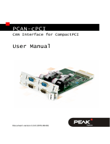
Figure 4: Possible assignment of connector X101
(represented only in network 0)
In the following chapters the possible assignments of I/O-connector X101 will be described.
CPCI-CAN/331 Hardware Manual • Doc. No.: C.2027.21 / Rev. 2.2 Page 17 of 37
X100
CompactPCI
Board-Connector
X101
CompactPCI
Rear-Panel I/O-
Connector
CompactPCI
Interface
CAN Controller
SJA1000
Variable
Use of
Resistors
ISO11898
CAN Interface
with Electrical
Insulation
DSUB
Connector
Male connector
X400A
Male connector
X400B
Flat cable
TTL LevelTTL Level
unidirectional or differential directly from CAN controller
ISO11898-CAN signals
ISO11898-
CAN Signals

CAN Signal Assignment of the CPCI-I/O-Connector
5.1 ISO11898 CAN Layer to X101
In standard design of the module the CAN signals of the two CAN interfaces are only assigned to
the DSUB connectors. By means of the connectors X400A, X400B, X410A and X410B the signals
can then be assigned to connector X101. This means that the signals are assigned to the DSUB
connectors and X101 at the same time!
If the ISO11898 CAN signals are to be assigned to X101, the pins of connectors X4x0A and X4x0B
(x=0, 1) have to be connected for each of both possible CAN channels.
CAN network Connections to connect ISO11898-signals to X101:
0 connect X400A to X400B
1 connect X410A to X410B
Table 5: Bridging ISO11898-CAN signals to X101
5.2 TTL-CAN Signals to X101
The assignment of the local CAN interface and the CompactPCI-I/O connector X101 can also be
changed by changing the resistors. Doing this, the CAN signals can be connected before the
ISO11898-interface and be assigned to X101. For this, available resistors have to be removed and
new ones have to be equipped.
NOTICE
Any intervention in the device by unauthorized persons voids warranty claims!
It is therefore recommended to send the CPCI-CAN/331 to esd for the change of the
resistors. The changes can be made by esd at your expense.
5.2.1 Comparison of Different Signal Assignments
Signal Assignment 1 (Standard):
In CPCI-CAN/331 standard the CAN signals of the CAN controllers are assigned to the local
ISO11898 interface (DSUB9). X101 is only assigned with GND signals.
Signal Assignment 2:
Alternatively the unidirectional CAN signals of the controllers can be assigned to the CompactPCI-
I/O connector X101. Assigning the signals to X101 and the DSUB connectors at the same time is
not permissible.
Signal Assignment 3:
Another alternative is to assign differential controller signals to connector X101. Doing this, the
controller has to be especially configured, because in standard configuration it uses the ports
unidirectionally.
Page 18 of 37 Hardware Manual • Doc. No.: C.2027.21 / Rev. 2.2 CPCI-CAN/331

CAN Signal Assignment of the CPCI-I/O-Connector
5.2.2 Changing the Signal Assignments
5.2.2.1 Signal Assignment 1: Unidirectional Signals to Local CAN Interface
Figure 5: Signal assignment 1
Resistor values:
CAN network 1
R403 = 10 kΩ
RX403 = 0 Ω
RX414A = 0 Ω
RX415A = 0 Ω
CAN network 0
R402 = 10 kΩ
RX402 = 0 Ω
RX404A = 0 Ω
RX405A = 0 Ω
CPCI-CAN/331 Hardware Manual • Doc. No.: C.2027.21 / Rev. 2.2 Page 19 of 37

CAN Signal Assignment of the CPCI-I/O-Connector
5.2.2.2 Signal Assignment 2: Unidirectional Signals to X101
Figure 6: Signal Assignment 2
Resistor values:
CAN network 1
R403 = 10 kΩ
RX403 = 0 Ω
RX414B = 0 Ω
RX415B = 0 Ω
CAN network 0
R402 = 10 kΩ
RX402 = 0 Ω
RX404B = 0 Ω
RX405B = 0 Ω
Page 20 of 37 Hardware Manual • Doc. No.: C.2027.21 / Rev. 2.2 CPCI-CAN/331
Page is loading ...
Page is loading ...
Page is loading ...
Page is loading ...
Page is loading ...
Page is loading ...
Page is loading ...
Page is loading ...
Page is loading ...
Page is loading ...
Page is loading ...
Page is loading ...
Page is loading ...
Page is loading ...
Page is loading ...
Page is loading ...
Page is loading ...
/