Page is loading ...

Operation
Installation
Maintenance Instructions
Replacement Kits
Pressure Balancing Shower/
Tub & Shower Valve
Z7300 Series
TEMP-GARD III
FOR OPTIMUM VALVE PERFORMANCE, BALANCE SUPPLY PRESSURES TO LESS THAN 5 PSI PRESSURE
DIFFERENTIAL BETWEEN HOT AND COLD WATER SUPPLIES.
2. Always install valve with mud guard (23) so that the indicated surface on mud guard is flush with finished wall.
The hole in the wall should be 4” in diameter.
3. If valve is to be used for a shower only, wrap threads on tub plug (24) with teflon tape and install plug into tub
port on shower valve.
4. When the final outer wall is finished remove mud guard and open both supply stops on valve by turning
counter clockwise.
5. Loosen and remove escutcheon (19) from valve. Carefully remove cartridge (10) from valve by holding
cartridge as close to the valve body (1) as possible and wiggling back and forth until cartridge comes out of
the valve. Place thumb and finger on gray part of cartridge to remove it, as shown in Figure 4.
6. With the cartridges removed from all valves in the system, turn on water supply and flush the system of any
debris. If the water coming out of the valve while flushing is going behind finished wall, a hose bib flushing out
kit (RK7300-20HB) may be used to allow the water to be directed to a drain by attaching a garden hose to
valve.
7. If hot and cold supply inlets are reversed simply remove cartridge and reinstall with cartridge flipped
180
o
. The handle adaptor (12) will need to be readjusted. To adjust handle adaptor remove and turn
180
o
. Handle should always turn through cold, then hot. Reinstall cartridge and tighten escutcheon to
150 in lbs. The system will need to be flushed again before installing shower heads.
8. To adjust temperature limit stop (11), turn valve to desired hottest temperature, remove temperature
limit stop (11) turn clockwise and reinstall so that the white protrusion on cartridge is touching the red
protrusion on the temperature limit stop.
9. After all flushing is done install shower heads and check system for leaks.
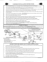
INSTALLATION OF TEMP-GARD III SHOWER VALVE
(Refer to page 4 for part no.)
AquaSpec
®
is a registered trademark
of Zurn Industries, LLC
©2010 Zurn Industries, LLC
1. Install rough piping
and valve body as
shown. Do not use
PEX or CPVC CTS piping
from valve to tub spout, as
the reduced ID results in
too much back pressure for
valve to function
properly. When facing
valve, HOT "H" is on
left and COLD "C" is on right.
Tub port “T” should face down
and shower port “S” should
face upward. The ears on the
valve at the 5 o’clock and
11 o’clock positions may
be used to attach the valve to
framing of wall if necessary.
WARNING: Caution should be
taken when heating valve for
sweat connections to avoid dam-
aging internal rubber and plastic
components in valve.
FIGURE 1
®
Form # CF1024 Date: 12/16/11 SHT 1 OF 4
C.N. No. 128417 Rev. G

10. Assemble external trim to valve.
•Hand tighten escutcheon nut (20) on valve.
•Remove tape from gasket (15) and adhere gasket (centered on the top half of the back of cover
plate (16)) so that 1/4 of the width of the gasket is sticking out beyond the back of the cover plate, see
Figure 2.
•Place cover plate over escutcheon (19) and fasten with screws (18).
•Install handle onto cartridge with handle pointed down. Tighten set screw.
The ZURN TEMP-GARD III Pressure Balancing Shower Valve is equipped with an adjustable temperature limit stop. The temperature
limit stop device is to be used to limit the valve handle from being turned to undesired hot water discharge temperatures. To adjust the
temperature limit stop, see step 8 of the installation and reference figure 3.
IMPORTANT: Failure to adjust the temperature limit stop properly increases the chances for serious injury.
WARNING: This shower system may not protect the user from scalding when there is a failure of other
temperature controlling devices elsewhere in the plumbing system.
Notes:
When there is a shutoff valve installed after the control valve, there shall be stop and check valves on the inlets. This is to
eliminate hot and cold cross-connection in the event the valve handle is left on. Specify suffix "-SC" for ASSE approved
checks.
If valve is going to be installed in “Thin Wall Application” such as a fiberglass or panel wall, it is recommended
that an optional wall flange (RK7300-WF) be used. This wall flange is used to sandwich the wall between the
valve body and cover plate.
OPERATION:
The main handle of the Temp-Gard III valve is for temperature control only. To turn valve on, the handle is turned
counterclockwise through the cold position, to the warm and then to the hot position. The range of motion on the
handle is 140
o
.
MAINTENANCE and SERVICE:
1. Remove handle (21) and cover plate (16).
2. Using a flathead screwdriver, turn both service stops (7) clockwise until they bottom out. This allows
the valve to be serviced without turning off the main water supply. If service stops need to be repaired
or replaced, the main water supply must be turned off and the service stop retainer (9) must be
removed by turning counterclockwise.
3. Remove escutcheon nut (20) and escutcheon (19).
4. Remove cartridge (10) by placing thumb and forefinger where shown in figure 4 and carefully wiggling
cartridge. Caution: If cartridge is not removed in manner described damage may occur to cartridge.
FIGURE 3
FIGURE 2
Cover Gasket:
Position gasket in back side of cover with the adhesive
against the cover and the open end at bottom as shown.
TEMPERATURE
LIMIT STOP
Adjusting Temperature Limit Stop:
Lift and turn temperature limit stop clockwise to reduce
maximum temperature.
15
Form # CF1024 Date: 12/16/11 SHT 2 OF 4
C.N. No. 128417 Rev. G

FIGURE 4
HOLD HERE TO REMOVE CARTRIDGE
5. To determine if the piston in cartridge is functioning properly, shake cartridge side to side. The piston
should make a clicking sound.
6. If no sound is heard when shaking, place cartridge in vinegar for at least 8 hours to remove scale and
debris. If still no sound is heard replace cartridge with RK7300-CART cartridge replacement kit.
Proper performance is dependent upon licensed, qualified personnel performing regular, periodic testing according to
ZURN specifications and prevailing governmental & industry standards and codes and upon following these installation
instructions. Failure to do so releases ZURN of any liability that it might otherwise have with respect to that device.
Such failure could also result in an improperly functioning device.
TROUBLE SHOOTING:
PROBLEM CAUSE SOLUTION
Valve will not flow water. Hot and cold water not turned on. Be sure both suplies are turned on
Service Stops not open. and service stops are open. Valve will
not operate unless both HOT and
COLD water inlets have pressure.
Water volume from valve is Pressure balancing piston housed in Remove and service cartridge as
inconsistent during operation. cartridge (10) assembly is blocked described in steps 1 through 6
from free movement by foreign of the MAINTENANCE and SERVICE
matter. section.
Valve delivers an insufficient quantity
of Hot or Cold water.
Temperatures fluctuate without moving
temperature handle.
Valve does not deliver Valve designed to deliver mixed
desired hot water temperature. hot and cold water in all handle
positions.
Temperature out of valve reduces Supply system is running out of hot Reduce maximum flow rate out of valve
gradually during use. water. or shower head. This will allow longer
period of use before reduction of hot
water supply.
Valve makes loud noise. Piston in cartridge is moving back
and forth because of a large pressure
differential between the HOT and
COLD water lines.
Alter the water system such that the
pressure differential at all shower
valves is no more than 5 psi.
Form # CF1024 Date: 12/16/11 SHT 3 OF 4
C.N. No. 128417 Rev. G
Increase system hot water
temperature.

PARTS:
1. Valve Body
2. Service Stop Washer
3. Service Stop Plunger
4. Spring
5. Stem O-Ring
6. Service Stop Roll Pin
7. Service Stop Stem
8. Retainer O-Ring
9. Service Stop Retainer
10. Pressure Balancing Cartridge
11. Temperature Limit Stop
12. Handle Adaptor
13. Set Screw
14. Wall Flange
15. Gasket (7000-90).
16. Cover Plate w/Etched Lettering
17. Temperature Indicator
18. Cover Plate Screw, 3”
19. Escutcheon (7300-81MT)
20. Escutcheon Nut (7300-9MT)
21. Handle
22. Set Screw
23. Mud Guard (7300-17)
24. Tub Plug (7300-7B)
25. Hose Bib
26. Escutcheon Extension
27. Set Screw
28. Stem Extension
29. Cover Plate Screw, 4”
REPLACEMENT KITS:
RK7300-CART
CARTRIDGE KIT
ITEM NO.
10. Pressure Balancing Cartridge
11. Temperature Limit Stop
12. Handle Adaptor
13 Set Screw
RK7300-50A
SERVICE/CHECK STOP KIT
(2) PER.
ITEM NO.
2. Service Stop Washer
3. Service Stop Plunger
4. Spring
5. Stem O-Ring
6. Service Stop Roll Pin
7. Service Stop Stem
8. Retainer O-Ring
9. Service Stop Retainer
RK7300-WF
WALL FLANGE KIT (OPTIONAL)
ITEM NO.
14. Wall Flange
RK7300-LH
LEVER HANDLE KIT
ITEM NO.
21. Handle
22. Set Screw
RK7300-11AE-001
COVER SCREWS KIT
(2) PER
ITEM NO.
18. Cover Plate Screw, 3”
RK7300-EXT
EXTENSION KIT (OPTIONAL)
ITEM NO.
26. Escutcheon Extension
27. Set Screw
28. Stem Extension
29. Cover Plate Screws, 4”
RK7300-20HB
FLUSHING OUT KIT (OPTIONAL)
ITEM NO.
25. Hose Bib
RK7300-8MT-002
COVER PLATE KIT
ITEM NO.
16. Cover Plate w/Etched Lettering
17. Temperature Indicator
PARTS BREAKDOWN
22
5
1
26
12
27
28
23
20
19
24
21
25
2
4
3
10
7
8
6
9
11
13
14
15
16
17
18
29
Form # CF1024 Date: 12/15/11 SHT 4 OF 4
C.N. No. 128417 Rev. G
ZURN INDUSTRIES, LLC.
♦♦
♦♦
♦
COMMERCIAL BRASS OPERATION
♦♦
♦♦
♦
5900 ELWIN BUCHANAN DRIVE
♦♦
♦♦
♦
SANFORD NC 27330
Phone: 1-800-997-3876
♦♦
♦♦
♦
Fax: 919-775-3541
♦♦
♦♦
♦
World Wide Web: www.zurn.com
In Canada: ZURN INDUSTRIES LIMITED
♦♦
♦♦
♦
3544 Nashua Drive
♦♦
♦♦
♦
Mississauga, Ontario L4V1L2
♦♦
♦♦
♦
Phone: 905-405-8272 Fax: 905-405-1292
/