Page is loading ...

CONGRATULATIONS!
Your new BriteStar Solar Aeration System by Vertex Water Features
includes a BriteStar Aeration cabinet with pre-assembled conduit
connections, two high efficiency solar panels, pre-assembled racking
and Vertex XL AirStations.
PRODUCT WARRANTY
3 year warranty on all components, repair or replace any
defective part.
Not covered: Air filters and compressor maintenance kit parts
5 year AirStation “No Questions” replacement policy
5 year solar panel warranty
All claims must be made to Vertex Water Features or an Authorized
Dealer. The customer is responsible for return shipping of any goods
for warranty inspection. After inspection, if the product shows a
manufacturing defect, Vertex will replace or repair parts at no cost to
the customer. Should inspection indicate non-warranty failure (faulty
installation, vandalism, negligence, etc.) warranty will be voided.
The period for all warranty work is equal to the remaining time period
of the original new equipment warranty. Warranty claims are based
on the date you purchase the product: mail the warranty card, call
844-432-4303 or go to www.vertexwaterfeatures.com/register-
warranty
WARNING! VOIDS WARRANTY:
Installing cabinet in a very low elevation may allow flooding to
occur - warranty does not cover damage from flood water that
destroys the compressor and/or electronics.
Installing the cabinet in an unusually dirty environment.
Excessive airborne dirt, sand or grit entering the cabinet will
damage the system.
Call your dealer or Vertex Water Features for help resolving
installation problems.
*Vertex reserves the right to change information without notice, and makes no
warranty, express or implied, with respect to this information. Vertex shall not
be liable for any loss or damage, including consequential or special damages,
resulting from the use of this info, even if loss or damage is caused by Vertex
negligence or other fault.
BriteStar Owner’s Manual
Battery Free Solar Aeration Systems
BATTERY-FREE SOLAR AERATION
CHECK MATERIALS UPON DELIVERY
FOR PRODUCT DAMAGED IN DELIVERY: The solar aeration system was properly
packed and accepted by the freight carrier for shipment. It is their responsibility to
deliver the system in perfect condition.
APPARENT DAMAGE OR LOSS: If upon delivery the equipment or containers
indicate DAMAGE IN TRANSIT, such goods should be refused or not accepted until
the transportation company’s agent has noted such on the freight bill. A copy of
such bill will be given to you, noting the nature and extent of the damage. If any
part of shipment is LOST IN TRANSIT, have shortage noted on freight bill
by agent.
CONCEALED DAMAGE: If damage is discovered, that was not apparent upon
delivery, notify the transportation company immediately to inspect damaged
equipment. The inspector will be required to provide a “CONCEALED BAD ORDER”
report. Inspections must be requested within 15 days of delivery. Do not move
damaged goods from original point of delivery. Retain all original packing and
containers for inspection. File a “FULL VALUE REPLACEMENT” claim against the
transportation company.
Hours of Operation: M-F, 8am – 5pm EST © Vertex Water Features
(844) 432-4303 www.vertexwaterfeatures.com info@vertexwaterfeatures.com
MATERIALS YOU NEED TO PROVIDE
(1) 3.5 in. OD, 3 in. ID steel pole. Standard length is 8 ft., though you may cut
shorter if you prefer the array to be lower. NOTE: The pole must be buried a
minimum of 3 ft. deep
Bags of Concrete: (12) 60lb bags or (9) 80lb bags
(2) 1/2” x 16” Rebar
(1) Bag of gravel for each AirStation
SAFETY NOTES
Please read the following instructions carefully before installing and operating your
system. Failure to follow the recommendations in this section may result in personal
injury or rescinding of the warranty agreement.
When near water always wear an approved life jacket and follow all water safety
guidelines.
Locate the cabinet on a solid support with adequate strength for the weight of
the unit.
Never push objects of any kind into the slots in the covers, as they may touch
dangerous voltage points or short out parts that could result in a risk of fire or
electrical shock.
Never override or “cheat” electrical or mechanical interlock devices.
Never attempt any maintenance or other activity that is not specified in
the user manual, or that is not specifically directed by an authorized Vertex
representative.
Never operate the system if unusual noises or odors are detected. Turn system
off by turning the breaker to the off position, and call Vertex to correct any
problems.
Before performing any maintenance and troubleshooting, disconnect the
electricity by turning the breaker to the off position.
TOOL CHECKLIST: Gather everything before starting
(2) 7/16 Wrenches
(2) 9/16 Wrenches
(2) 3/4 Wrenches
A-Frame Ladder
Compass
Flat head screw driver
Level
Phillips Head Screwdriver
Post-hole digger
Shovel
Tape Measure

2
Vertex Water Features
SOLAR AND CABINET INSTALLATION
SITE SELECTION
Locate solar panels facing south where there is no shading from early morning to late
afternoon.
Be aware of tall objects such as buildings, poles, and trees whose shadows will
decrease the pumping rate. Even slight shading of solar panels significantly reduces
power output.
Solar panels face south in the northern hemisphere and north in the southern
hemisphere.
If installing close to pond, install far enough inland to avoid flooding of the compressor
cabinet.
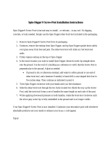
POLE INSTALLATION: SEE FIGURE 1
NOTE: Use a tape measure to get correct depth and width
In windy conditions, stress is put on the pole’s foundation due to the surface area of the
array and if the concrete mixture and curing process is less than perfect some shrinking of
the concrete occurs allowing the array pole to rotate in the concrete.
Pole should be 3.5 in. OD, 3 in. ID and a maximum length of 8 ft.
Using a shovel and post-hole digger, dig a hole a minimum of 3 ft. deep by 2 ft. wide.
To prevent the array from rotating, the pole should be drilled out with a 5/8” bit to
allow ½” rebar cut to a 16” length to be hammered into the pole at a cross angle in
the concrete. Locate the holes for the two rebar crosspieces by measuring up from the
bottom.
Place pole in the center of the hole and begin pouring the mixed concrete.
During pouring the concrete continue to adjust the levelness of the pole using a level.
(2) High Efficiency Solar Panels (1) Assembled Top of Pole Racking (1, 2, or 3) XL1 AirStations (1) XL1 and (1) XL2 AirStation
(1) Prewired BriteStar
Aeration Cabinet
(1) 15’ Male MC4 Extension Cable
with MC4 Coupler
(1) 15’ Female MC4 Extension Cable
with MC4 Coupler
(8) Panel Racking Bolt sets
(4) Panel Cable Clips (10) Tywraps
SYSTEM MATERIALS LIST: Verify that you received everything
Figure 1: Pole Installation
GROUND LEVEL
3.5 IN. OD GALVANIZED PIPE
- 8’ for Normal height:
5’ above ground
- 6’ for low profile - shown:
3’ above ground
3 FT.
18 IN. BY 3 FT. HOLE
FILLED WITH CONCRETE
1/2”
X
18” REBAR
1 FT. DOWN
2 FT. DOWN
15° TILT
OR

3
Owners Manual
GROUNDING: NEC ARTICLE 690
We recommend grounding your equipment according
to National Electrical Code (NEC) regulations. If you
have any doubts on proceeding yourself, contact your
local electrician to install the grounding rod and ground all
equipment properly.
INSTALLING PANEL RACKING: SEE FIGURE 3
The racking is shipped preassembled.
Line up the mounting sleeve with the top of pole and
lower into place.
Panels must face south [A] - use a compass to achieve
the correct orientation.
Mark the pole and sleeve with a permanent marker for
alignment purposes
Using a 9/16 wrench tighten the two set bolts [B] to 32-
34 ft.-lbs of torque.
INSTALLING PANELS: SEE FIGURE 4
Set the racking to the 15 degree setting to install panels
Place one panel on the racking and line up the panel
with the mounting holes on the racking
Using the provided fasteners loosely fit the panels on
the racking.
After panel is fitted with all fasteners in place tighten
down all the fasteners to 6-8 ft.-lbs of torque.
Repeat these steps for the second panel.
After panel installation, adjust tilt to desired angle.
PANEL ORIENTATION: SEE FIGURE 5
The tilt angle should be adjusted to capture optimal
sunlight.
Remove the 3/8 bolt from the support bar [C].
Insert 3/8 bolt in the correct elevation set point for your
location and the season listed below.
Tighten the nut on the opposite side.
Best Solar Panel Angle by Season
Your
Latitude
Summer
JUN 21
Autumn
SEP 21
Winter
DEC 21
Spring
MAR 21
25° 15 25 45 25
30° 15 25 45 25
35° 15 35 55 35
40° 15 35 55 35
45° 15 45 65 45
50° 25 45 65 45
Figure 4: Installing Panels
15°25°35°45°55°65°
Figure 5: Panel Orientation
SUPPORT BAR
ELEVATION SET POINT GAUGE
C 3/8 BOLT
MOUNTING SLEEVE
MOUNTING POLE
B SET BOLTS
A STRONGBACK -
POINT IT SOUTH
Figure 3: Panel Racking Installation

4
Vertex Water Features
CABINET INSTALLATION
Set aeration cabinet at desired location within reach of the solar panel wires.
Cabinet ships with mounting pad attached. Use a cement pad if needed in areas where vandalism or severe weather is a potential problem.
For proper cooling, cabinet must have a minimum clearance of any obstruction of 1 foot around the unit’s perimeter.
If using the mounting pad, clear the ground of any rocks, sticks and debris that will prevent the pad from sitting flat. You may need to use a shovel to level
the ground to achieve this.
To minimize compressor noise, place cabinet directly on the ground, surrounded by landscaping away from concrete walls.
NOTE: Place the pad so that the air lines leaving the cabinet face the lake.
If using a cement pad: remove the mounting pad from the cabinet, set cabinet in the center of pad, fasten the cabinet feet directly to the cement pad.
Attach the solar panel wires to the pole using the ty-wraps included in the shipment.
WIRING SYSTEM: MAKE SURE BREAKER IS IN THE OFF POSITION AND FOLLOW THE STEPS IN THE ORDER GIVEN!
1. Remove the BriteStar cabinet lid
2. Check to make sure the breaker is in the OFF position
3. Using the two MC4 couplers (M/M/F, F/F/M), connect the two positive leads from the panels
into the labled positive branch connector and the two negative leads from the panels into the
labeled negative branch connector [FIGURE 9 - 10].
4. Secure the cables to the underside of the panels using the panel cable clips.
5. Coil and ty-wrap the solar panel cable to the panel racking
6. Turn breaker on to test start the system.
WARNING:
Once the connection is made, power
is owing into the breaker box
Figure 9: Connecting to Panel
NEGATIVE
POSITIVE
NEGATIVE
NEGATIVE UNION
POSITIVE
POSITIVE UNION
PANEL CABLE CLIPS
Figure 10: Connecting to Panel Close-up
POSITIVE FROM PANEL 2
POSITIVE FROM PANEL 1
NEGATIVE FROM PANEL 2
NEGATIVE FROM PANEL 1
A
AIRSTATION VALVES
B CABINET FAN AND GUARD
C ELECTRICAL BREAKER
D INTAKE FILTER/MUFFLER
E PRESSURE RELIEF VALVE
F PRESSURE GAUGE
G
DRIVER ENCLOSURE
A
C
D F
B
ED
C
G

5
Owners Manual
WARNING:
When in or around water always wear an approved life jacket and follow all water safety guidelines.
AIRSTATION INSTALLATION
The ability of the system to aerate depends on the proper positioning of the diffusers. Diffusers should be placed in the deepest and widest areas of the water
body to be most efficient. If more than one diffuser is being installed they should be equally spaced throughout the deeper areas. If you need help determining
AirStation placement call Vertex Water Features at 800-432-4302 and ask for the Aeration Sales Department for free technical advice.
Know where you intend to place the diffuser before starting the installation process. Materials for set-up screw driver, hose clamp, utility knife, BottomLine air
tubing, and enough rope to reach the lake bottom and back: 10’ (3.0 m) depth = 20’ (6.1 m) rope).
START-UP PROCEDURE
WARNING:
Always follow this procedure for new installations, when restarting in the spring, and anytime the system has been turned off for
a month or more. On start-up, the aeration system circulates deep, poor quality water that accumulated over time upward to the pond’s surface,
introducing harmful gasses into the previously healthy upper regions of the water column. This movement of water can temporarily affect aquatic life and
could result in a fish kill. NOTE: These start-up procedures are a general guideline, for any questions and/or concerns, contact Vertex Water Features at 800-
432-4302 for technical assistance.
To prevent a sh kill, Vertex has established the following start-up procedures, this should take 6 days:
Turn on system by tuning the breaker box switch inside the cabinet to the on position and operate for 15 minutes.
Turn off system for remainder of the day.
Restart the system the next day and operate for 30 minutes. Turn off system for the remainder of day.
Each day double the operating time from the previous day until the system is running continuously. This should take 6 days.
DO NOT USE TEFLON TAPE! Screw diffuser
discs onto riser pipes, do not cross thread.
DO NOT OVER TIGHTEN DISK.
1
Assemble all the materials you will need on the
boat - see list on page 1. Pick up airstation by black
base only.
2
Uncoil supply tubing along the shore, making sure
tubing is not twisted or tangled. Leave 4' tubing on
shore and secure one end of the tubing so that it
doesn't follow you into the water.
3
Thread rope through the two holes on the base until
the rope is evenly distributed. If Airstation may be
moved later on, tie one end of rope to the unit and,
after it settles, tie the other end to a buoy or decoy
on the surface of the water.
6
Holding both ends of the rope in your hand, lower
the diffuser assembly into the water. Once unit is on
lake bottom, release one end of the rope and pull
rope into the boat.
7
Head out with the other end of the tubing. Make sure
the propeller and tubing do not get tangled up.
4
At the drop site, connect the tubing to the barbed
tting. Use PVC cement and let dry (recommended
method), or...
5a
Connect the tubing to the barbed tting with a stain-
less steel hose clamp.
5b
OR

6
Vertex Water Features
MULTIPLE AIRSTATION™ BALANCING
WARNING:
If the system has been installed in an established pond and you are attempting to balance the AirStations during the rst day
of operation, make certain that this procedure takes as little time as possible. Under 15 minutes is preferred. See “System Start-up Procedures”
section for details.
Once the installation of a multiple AirStation system has been completed, proper balancing of the AirStations is required to ensure that they all get an equal
amount of air. The control valves for each AirStation are located inside the cabinet, unless a VBS (Valve Box System) was installed. In the instance that a
Remote VBS was installed, the control valves will be inside the valve box, buried to ground level, down by the shoreline.
Use a 7/16" wrench to unscrew the bolts and remove the cabinet lid. Close the AirStation valve with the shortest (or most shallow) run of tubing. With one valve
wide open, partially open the valve that controls the air flow to the other AirStation. Adjust the second valve until a boil is noticed above this AirStation. Once
there is air to both of the AirStations, check to be sure both boils are approximately the same size. If they are not, make small adjustments as necessary to
even them out. At this point, we suggest making indicator marks with a permanent marker from the valve handle to the valve body to assist you in rebalancing
the system in the future. The overall goal when adjusting the valves is to balance the AirStations at the lowest possible pressure. The lower the system pressure
the higher the total air flow.
OPERATION/MAINTENANCE/CLEANING INSTRUCTIONS
WARNING:
MAKE SURE BREAKER IS IN THE OFF POSITION BEFORE STARTING ANY WORK
Only use parts that are supplied or approved by Vertex. Use of other parts may result in poor performance, could create a hazardous situation and
void the warranty.
Do not use acid or corrosive cleaners. Follow instructions in this manual for the appropriate cleaning methods.
Refer servicing to a qualified electrician when compressor fan or other electrical components need service or the cabinet is producing unusual
noises or odors.
Your BriteStar solar aerator starts and stops automatically depending on the amount of sunlight striking the solar panels. Because the system can start and
stop unexpectedly, always turn breaker swich off before servicing the unit.
BriteStar solar aerators have an auto power sensing capability that turns on the system when there is sufficient sunlight and turns off the system when there is
too little light to generate the necessary power to run the compressor. BriteStar solar aerators are designed to run on as little as 15% of full sunlight powering
through most cloudy days. If cloud cover is too severe the system will turn off until sunlight levels increase and then it will automatically restart.
During early morning hours, the system will start after the sun rises. If there is insufficient sunlight available to maintain proper voltage the aeration system will
shut off. It will continue this cycle until there is sufficient power to run continuously.
At the end of the day the aeration system will cycle off and on as sunlight diminishes until the system shuts down for the night.
Vertex aeration systems are designed for low-maintenance and typically only require minimal scheduled maintenance. Periodic cleaning and/or replacement
of the panel, compressor air filter, piston cup, and “flexing” of the AirStation is required. Keep cabinet air inlets and outlets free of debris and weed growth to
allow normal ventilation. If size and appearance of any surface boil has decreased from initial installation, perform one or both of the following:
AIR FILTER REPLACEMENT
Air filter replacement should be done at least 4 times per year or every 3 months when systems is running. A
dirty filter reduces air flow and shortens the life of the compressor. Unscrew the old filter, discard and screw on
the new filter.
SOLAR PANEL MAINTENANCE
Cleaning panels every 3 months or as
needed with water and a rag to keep
glass surface clear
Adjust panel tilt angle each season per
schedule on page 3
GENERAL CABINET CLEANING
1. Disconnect the electricity by turning the breaker to
the off position
2. Use a 7/16” wrench to unscrew the bolts and remove
the cabinet lid
3. Using a portable vacuum or rag, remove debris, grass clippings and dirt from inside cabinet
4. Remove anything blocking the cabinet intake vents or exhaust vents
On the outside back cover of this Owner’s Manual, you will find a Vertex parts list that provides you the necessary information for ordering replacement parts.
Call your local dealer or Vertex at 844-432-4303 with your 4 digit system warranty number or serial number off of the silver sticker located inside the cabinet.
Vertex can also supply you with the necessary replacement parts information.
PISTON CUP REPLACEMENT
Under normal year-round, continuous use, the compressor piston cups typically last 12-18 months depending upon the environmental conditions. Replace the
piston cups when you notice a drop in air flow (despite air filter replacement) resulting in smaller surface boils or an increase in compressor noise.
CABINET COOLING FAN REPLACEMENT
Cooling fans provide critical cooling for the cabinet components. If the cooling fan fails, cabinet temperatures will increase and may damage the compressor
system. We recommend replacing the cooling fan during compressor piston cup replacement.
Contact Your Dealer or Vertex for compressor service and/or parts: 844-432-4303

7
Owners Manual
DISK FLEX-CLEANING PROCEDURES
SINGLE AIRSTATION SYSTEMS MULTIPLE AIRSTATION SYSTEMS
Remove the cabinet lid Remove the cabinet lid
Locate pressure release valve (pg.4 E) Close one of the two valves (pg.4, E)
Using the attached ring on the pressure release valve, pull back gently so air releases through the
valve. Hold for 2 seconds then close. If it doesn't return, gently twist until it does.
Fully open the remaining valve
Fully close the open valve for two seconds then return to the open position. The pressure release
valve will activate when closed. This is ok.
Repeat four more times, total of ve exes.
Repeat four more times, total of ve exes.
With the one valve fully open, open the second valve. Now close the valve that was just used and
repeat exing for the second valve.
Set valves to their previous setting for balanced airow.
Reattach lid Reattach lid
OPERATING THE SYSTEM IN THE WINTER
Vertex Aeration Systems are designed to operate year-round in cold climates with these important precautions. To run aeration in winter:
WARNING:
Drowning warning: Operating in freezing conditions on an ice-covered lake will cause large open water areas to remain
at the boil sites. The ice thickness around these open areas will be much thinner than the ice over the rest of the lake. Injury or fatality may
result from falling through the ice. Vertex strongly recommends that this danger of thin ice around the boil area be clearly posted at frequent
intervals. Owner assumes all responsibility for operating Vertex aeration systems during winter months.
To prevent risk of over cooling the entire water column, AirStations should be moved to a shallower portion of the waterway (typically one-half the depth of
original placement) and operated there until warmer temperatures return, this will safeguard fish by allowing warmer water to remain in the lower regions of the
waterway. Check panels and cabinet area as often as necessary for snow accumulation and clear away as required.
If you choose to turn off the system and store it for the winter then turn off the breaker and disconnect the airline tubing, MC4 couplers and grounding wires.
Store the cabinet inside a protective building. In the spring reconnect the MC4 couplers and grounding wires and reattach airlines. Turn the breaker to the on
position to restart the system. If no air is flowing to diffusers and the pressure relief valve actuates for more than a few minutes the airlines may be plugged
with ice. Add one cup of denatured alcohol to each airline and wait one or more hours. The alcohol will melt the ice enough to allow the compressor to push air
through the line. Follow the start-up procedures described on page 6.
TROUBLESHOOTING GUIDE
ISSUE CHECK LIKELY CAUSE CORRECTION
No bubbles at ANY AirStations.
Compressor/cabinet fan not
running
1. Check if breaker tripped Either compressor or fan is locked up Contact Vertex or local dealer for instructions
2. Shading Insufcent sunlight Wait for sufcent sunlight then reevaluate
Time delay in process Wait 15 minutes for automatic restart
No bubbles at ANY AirStations.
Compressor/cabinet fan both
running
1. No air leaks are audible in cabinet. Compressor running
louder, possible excessive vibration
Compressor mufer lter is dirty/clogged
Replace lter. NEVER attempt to clean or re-install
a wet lter
2. Compressor operating normally but making unusual
noises. Exhibits reduced pressure/air ow
Compressor needs piston rebuild kit and possibly
new mufer lter
Contact Vertex or local dealer with specications for
rebuild kit. Keep mufer lter clean
No bubbles at one or both
AirStations. Compressor/
cabinet fan are running
Check for leaks at all connections in line and in cabinet. If
none are audible, carefully spray SMALL amount of soapy
water onto connections and look for bubbles
Vibration loosened connection or cracked tting Tighten connection, replace cracked tting
No bubbles at only one of
two AirStations. Compressor/
cabinet fan are running
1. That all valves in cabinet wide open Improper "balancing" of AirStations
Adjust valves on manifold in cabinet until all
AirStations operate properly. See "AirStation
Balancing" section
2. Valves in cabinet are properly "balanced" and no leaks
are evident
Compressor beginning to lose compression -
needs piston rebuild kit
Contact Vertex or local dealer with compressor
specications for rebuild kit. Keep mufer lter clean
Large rolling bubbles instead of
ne bubbles at surface above
one or more AirStations
Inspect each AirStation for malfunction
Diffuser membrane damaged, or AirStation tting
broken
Call Vertex or local dealer for repair/replacement
Air coming out of pressure
relief valve
1. High pressure reading on gauge. Inspect AirStations and
tubing for clogging
All valves closed too much Rebalance air ow to AirStations
Airlines iced up Add 1 cup of denatured alcolhol to each airline
2. Low pressure reading on gauge. AirStations not clogged Bad pressure relief valve. Contact Vertex or local dealer for repair/replacement
Compressor stops working for
periods of time, then restarts
Shading
Defective driver Call Vertex
Insufcent sunlight Wait for sufcent sunlight then reevaluate.
Compressor shakes erratically
and makes load noises
2. Check for clogged mufer Mufer lter in need of replacement Replace lter
Compressor running at low
speed
Turn aerator off. Check incoming voltage Low Voltage
Clean solar panels. Check that the panels are facing
south. Adjust the panel tilt angle
Check sunlight Shading Wait for sufcent sunlight then reevaluate

MAINTENANCE SCHEDULE
WARNING:
To prevent severe shock or electrocution, Disconnect the electricity by turning the breaker to the off
position.
Date:
Maintenance Performed:
Date:
Maintenance Performed:
Date:
Maintenance Performed:
Date:
Maintenance Performed:
Date:
Maintenance Performed:
Date:
Maintenance Performed:
Hours of Operation: M – F, 8am – 5pm EST
Phone: (844) 432-4303
Website: www.vertexwaterfeatures.com
Email: info@vertexwaterfeatures.com
REV.051016
/