Page is loading ...

<
IA657: A
>
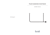
Drain pipe
Must be installed separately.
Insulate indoor part of pipe to
prevent condensation.
SYSTEM SINGLE DUCTING
UNIT AIR CONDITIONER
INSTALLATION MANUAL
O
+ – Screwdriver
O
Measuring Tape
O
Knife
O
Saw
O
ø 65mm Power Drill
O
Allen Key ( 4mm)
O
Wrench (14, 17, 19, 22, 24, 27mm)
O
Gas Leakage Detector
O
Pipe Cutter
O
Plastic Tape
O
Pliers
O
Flare Tool
O
Carefully read through the procedures of proper
installation before starting installation work.
O
The sales agent should inform customers regarding
the correct operation of installation.
Tools Needed For Installation Work
SAFETY PRECAUTION
O
Read the safety precautions carefully before operating the unit.
O
The contents of this section are vital to ensure safety. Please pay special attention to the following sign.
WARNING ........ Incorrect methods of installation may cause death or serious injury.
CAUTION ......... Improper installation may result in serious consequence.
Be sure that the unit operates in proper condition after installation. Explain to customer the proper way of
operating the unit as described in the user’s guide.
!
!
Indoor Unit
Outdoor Unit
RPI-30MH1
RAC-30MH1
WARNING
!
CAUTION
!
O
Please request your sales agent or quali ed technician to install your unit. Water leakage, short circuit or re may occur if
you do the installation work yourself.
O
Please observe the instructions stated in the installation manual during the process of installation. Improper installation may
cause water leakage, electric shock and re.
O
Make sure that the units are mounted at locations which are able to provide full support to the weight of the units. If not,
the units may collapse and impose danger.
O
Observe the rules and regulations of the electrical installation and the methods described in the installation manual when
dealing with the electrical work. Use power cables approved by the authorities of your country.
O
Be sure to use the speci ed wire for connecting the indoor and outdoor units. Please ensure that the connections are tight
after the conductors of the wire are inserted into the terminals. Improper insertion and loose contact may cause over-heating
and re.
O
Please use the speci ed components for installation work. Otherwise, the units may collapse or water leakage, electric shock
and re may occur.
O
Be sure to use the speci ed piping set for R22. Otherwise, this may result in broken copper pipes or faults.
O
When installing or removing an air conditioner, do not allow air or moisture to remain in the refrigeration cycle. Otherwise,
pressure in the refrigeration cycle may become abnormally high so that a rupture may be caused.
O
Be sure to ventilate fully if a refrigerant gas leak while at work. If the refrigerant gas comes into contact with re, a poisonous
gas may occur.
O
After completion of installation work, check to make sure that there is no refrigeration gas leakage. If the refrigerant gas
leaks into the room, coming into contact with re in the fan-driven heater, space heater, etc., a poisonous gas may occur.
O
Unauthorized modi cations to the air conditioner may be dangerous. If a breakdown occurs please call a quali ed air
conditioner technician or electrician. Improper repairs may result in water leakage, electric shock and re, etc.
FOR SERVICE PERSONNEL ONLY
THE CHOICE OF MOUNTING SITE
(Please note the following matters and obtain permission from customer before installation).
WARNING
O
The unit should be mounted at stable, non-vibratory location
which can provide full support to the unit.
WARNING
O
The outdoor unit must be mounted at a location which can support heavy
weight. Otherwise, noise and vibration will increase.
CAUTION
O
No nearby heat source and no obstruction near the air outlet is
allowed.
O
The clearance distances from top, right and left are speci ed in
gure below.
O
The location must be convenient for water drainage and pipe
connection with the Outdoor unit.
O
To avoid interference from noise please place the unit and its
remote controller at least 1m from the radio, television and inverter
type uorescent lamp.
O
To avoid any error in signal transmission from the remote controller,
please put the controller far away from high-frequency machines
and high-power wireless systems.
O
The installation height of indoor unit must be 2.3m or more in a
non public area.
CAUTION
O
Do not expose the unit under direct sunshine or rain. Besides, ventilation
must be good and clear of obstruction.
O
The air blown out of the unit should not point directly to animals or plants.
O
The clearances of the unit from top, left, right and front are speci ed in gure
below. At least three of the above sides must be open air.
O
Be sure that the hot air blown out of the unit and noise do not disturb the
neighbourhood.
O
Do not install at a location where there is ammable gas, steam, oil and
smoke.
O
The location must be convenient for water drainage.
O
Place the outdoor unit and its connection wire at least 1m away from the
antenna or signal line of television, radio or telephone. This is to avoid noise
interference.
INDOOR UNIT
OUTDOOR UNIT
!
!
!
!
Accessories to indoor Unit:
Other optional parts for display
panel & wireless remote control
SPX-RCK4
Display panel
Panel installation plate
Panel cover
Remote controller (wireless)
Holder for remote control
3.1 x 16 screw
Item QuantityNo.
1
2
3
4
5
6
1
1
1
1
1
2
O
Install the indoor unit with a proper
clearance around it for operation and
maintenance working space.
O
In case that the ceiling board can not
be detected for servicing, prepare a
service access door below the indoor
unit for removing the indoor unit.
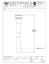
Dimension of Mounting Stand
of the outdoor unit
3
Bush
Names of Outdoor Components
QtyNo. Item
Drain Pipe
1
11
12
Bush
1
13
Figure showing the Installation
of Indoor and Outdoor Unit.
CAUTION
!
CAUTION
Always install the indoor unit
level. Units not installed level
may leak.
!
The indoor piping should be insulated
with the enclosed insulation pipe. (If
the insulator is insuf cient, please
use commercial producrts.)
CAUTION
O
Discharge grille and suction grille
shall be covered by insulation
material to prevent water drop.
!
O
The difference in height
between the indoor and
outdoor unit should be
kept below 30m.
O
The connecting pipe,
no matter big or small,
should all be insulated
with insulation pipe and
then wrapped with vinyl
tape. (The insulator will
deteriorate if it is not
wrapped with tape).
O
Need a connecting work for refrigerant pipe, drain pipe and F cable in the ceilling after suspending the indoor unit. Arrange
drain pipe, refrigerant pipe and F cable in their installation position.
O
For nishing of opening on ceiling, arrange with builder in detail.
O
If ceilling is already completed, connecting cables between indoor and outdoor, piping and drain piping must be done before
tting indoor unit.
Opening on ceiling & suspension bolt
1
Wall Penetration and Installation of Protection Pipe
O
Drill a ø 65mm hole on wall which is slightly tilted towards the outdoor side. Drill the wall at a small angle.
O
Cut the protection pipe according to the wall thickness.
O
Empty gap in the sleeve of protection pipe should be completely sealed with putty to avoid dripping of rain water into the room.
Be sure that the wire is not in contact
with any metal in the wall. Please use
the protection pipe as wire passing
through the hollow part of the wall so
as to prevent the possibility of damaged
by mouse.
Preparation for installing indoor unit
2
Installation of suspension bolts
O
Be sure to reinforce furring of ceiling (frame : ceiling joints and supporter) to maintain level of ceiling and prevent vibration
of ceiling plate.
O
Suspension bolts should be purchased in the eld.
O
Refer to diagrams shown below for length of suspension bolts.
O
In case of wooden frame
O
In case of steel frame (Unit : mm)
Be sure to use protection pipe (commercial
product).
If connecting cables are touching metal lath inside
the wall or inside the wall is hollow where mouse can
bite cables, it can cause electrical shock or re.
If sealing is not complete, high humidity air from
inside the wall or outside of the room can come in
and cause water dripping.
O
When the relative humidity of inlet or ambient air exceeds 80%, apply an ( eld-supplied) auxiliary drain pan beneath the indoor unit
as shown below
Drain pipe installation
O
Prepare polyvinyl chloride pipe with a 32mm outer diameter.
O
Be sure to roll an insulation (thickness 10mm or more) for the drain pipe at indoor side.
O
Always draw the drain pipe downward so that water ows smoothly. Fix it (ex. by hanger) to prevent a peak and trap.
!
WARNING
!
CAUTION
O
A circuit breaker or fuse (20A time delay) must be installed. Without a circuit breaker or fuse the danger of electric shock
exists.
A main switch with a contact gap of more than 3mm has to be installed in the power supply line to the outdoor unit.
O
Do not install the unit near a location where there is ammable gas. The outdoor unit may
catch re if ammable gas leaks around it.
O
Please ensure smooth ow of water when installing the drain hose.
O
Piping shall be suitable supported with a maximum spacing of 1m between the supports.
Be sure to
completely
seal any
gap with
putty.
O
In case drain piping cannot be done smoothly due to obstacles, it can also be arranged outside of the main unit as shown in the
drawing below.
O
Maximum drain-up length shall not more than 500mm height.
Installation of Drain Pump (Optional)
In case the pipe length is more than 5m,
add refrigerant R22 at 35 gram per every
meter exceeds. However, pipe length shall
not exceed 50m.
!
CAUTION
QtyNo. Component’s Name
Washer(M10)
Screw (4mm)
Hose Clamp
Insulation (22IDx130)
Insulation (43IDx130)
Binder
Remote Controller
Screw for holder of
Remote Controller
Filter Holder
Screw for Filter Holder
mounting stand
(unit : mm)
Service Access
Door (Min. 450)
Electrical Box
Rear Side
Min. 600
View from Top
Min.
600
Front Side
Min.
1000
Min.
1000
Maximum pipe length 50m
Minimum pipe length 5m
Above 100mm
give clearance
as wide as
possible
Above 200mm
Above 50mm when
installed on the
ceiling of balcony
Above 200mm
Above 100mm
Above 500mm
980 (for Suspension Bolt)
Unit : mm
Wired remote controller
(for Suspension Bolt)
Refrigerant Gas Pipe Connection
Refrigerant Liquid Pipe Connection
Drain Pipe Connection
(Gas pipe)
(Liquid pipe)
(Drain pipe)
(for Suspension Bolt)
Bend slip-
preventive metal
C type
metal
Long nut
Suspension
bolt (M10)
Insert 980 ~ 1470N
(100 ~ 150kgf)
150 ~ 160mm
Concrete
Reinforcing
bar
Suspension bolt (M10)
Hanger bolt
Angle
Ceiling
Suspension
bolt (M10)
H beam
Suspension
bolt (M10)
Ceiling
Nut
AngleNut
Suspension
bolt (M10)
Angle
60 ~ 90mm square piece of lumber
About 75
About 75
Seal with putty
Seal with putty
Sleeve of
protection pipe
Protection pipe
WALL
Indoor
Outdoor
Downward 1/25 ~ 1/100
Seal
Insulation (Thickness
10mm or more)
Trap
No insulation
Stagnant water
Drain Piping (PVC TUbe, VP25)
(Field-Supplied)
1/25 to 1/100 Down-Slope
Suspension Bracket
(Field-Supplied)
90° Elbow Pipe (VP25)
(Field-Supplied)
Lift Piping For Drain-Up
(PVC Tube, VP25)
(Field-Supplied)
90° Elbow Pipe (VP25)
(Field-Supplied)
Indoor Unit
Hose Clamp
Drain Pan
Drain Pump
(Optional)
(Max.) 374 to 500 (Drain-Up Length)
To the Atmosphere
Auxiliary Drain Pan
(Field-Supplied)

Installation of Indoor Unit
3
Marking of the Positions of the Sling bolts and Piping Connections
1. Mark the positions of the sling bolts, refrigerant piping connections and drain connection.
2. Ceiling Work: it basically varies according to the building structure.
Consult with the architect or interior nish worker for more information on this.
(a) To maintain the appropriate levelness of the ceiling and preventing from the vibration, the additional reinforcement in the
ground of ceiling (Building Frame) is essential.
Also, rubber cushion can be applied for the insuf cient strength of the frame around the sling part on the ceiling.
(b) Provide a space for the air inlet grille, air outlet grille and maintenance work.
(c) Do not suspend the indoor unit and electric light units from the same auxiliary supporting beams, and do not connect the
suspension bolts on the indoor units. If connected, the light may icker or the light unit may be rattled by vibration of the indoor
units.
Mounting the indoor unit
Hanging indoor unit
1. How to put Nuts or Sling Bolts
Put nuts on each of the four hanging bolts.
2. Hanging the Indoor unit
O
Hook suspension bracket to the nut and washer of each hanging bolt, as shown, starting
at the opposite side to service cover side.
O
After checking that the nut and washer are correctly xed by the retainers of the suspension bracket, hook the suspension
bracket of the service cover side to the nut and washer. (Put the sling bolts away from the unit when hooking.)
O
Piping and wiring work will be required in the ceiling after hanging the unit. Therefore, determine the drawing direction of pipe
after selecting the installation location, particularly if the ceiling was existed.
piping and wiring work should be carried out up to the connecting positions before hanging the unit.
3. For reasons of the disaster prevention, the distance between under the roof and wall surface should be followed as shown in
the below gure.
O
Use the non ammable material for the duct.
O
Select the indoor unit position, xing direction of air outlet so that cool/hot air reaches all the room. Standard position of the
indoor unit is with the wall side on the ceiling.
Connecting Return Duct and Supply Duct
1. The return duct should be connected with the indoor through canvas ducts between inlet side of the indoor unit and ceiling of
the room. The supply duct should be connected with the indoor unit through canvas ducts, in order to avoid abnormal sound
vibration. The unit is equipped with a pre-drilled duct ange for the return and supply duct connection.
2. Attach the vibration proof rubber to Sling Bolt in order to avoid abnormal sound vibration.
3. Undamped natural frequency is 9 to 21 Hz.
4. Duct material should be non- ammable material.
5. Perform the heat insulation work over the duct and the duct ange for dew protection.
O
If a lower sound level is further required, install silencer ( eld-supplied).
O
The facility design should be “Unit External static Pressure = Duct Pressure Loss Suction / Discharge Loss”. If the duct
pressure loss becomes under to the unit external static pressure, air speed will get larger and lead to the occurrence of
louder noise, splashing water and activation of motor protection circuit, and if the unit external static pressure becomes
under to the duct pressure loss, some problems such as inability to change the air speed may occur. Set the air ow control
damper or shift the static pressure control switch to adjust to get almost equal level between the external static pressure
and the duct pressure loss. (See “Setting of External Pressure” section for the details.)
O
Basically this unit is designed to install the ducts on the inlet side and the outlet side.
Ask for more information for using the return ducts in the ceiling.
Adjusting of the Unit Level
1. Check to ensure that the foundation is at, taking into account the maximum foundation gradient.
If not, it will occur malfunction of oat switch or not operation. Then it will drop the drain water from the ceiling.
2. The unit should be installed so that the rear side of the unit is slightly (0mm to 5mm) lower than the front side, in order to
avoid the incorrect position of the drain discharge.
3. Tighten the bolts of the sling nuts with the suspension brackets after adjustment is completed. Special plastic paint must be
applied to the bolts in order to prevent them from loosening.
Keep the unit as well as relevant equipment covered with the vinyl cover during installation work.
Connection of drain pipe
4
CAUTION
!
1
1
4. If decided to keep the ange at discharge side, x screw 2 at 8 positions. However, if decided not to keep the ange,
remove 4 screws that xed to the ange.
Field-Supplied Parts
*Sling Bolts 4-M10 or W3/8
*Nut 8-M10 or W3/8
Sling Bolts (4-M10 or W3/8)
(Field-Supplied)
Nut & Washer
(4-M10 or W3/8)
Nut (Field-Supplied)
Washer (Accessory)
Suspension
Bracket
False Ceiling Side
Retaining Nut
Washer
Indoor Unit
Washer
Nut
Approx.50
Sling Bolt
Suspension Bracket
Left Side
Right Side
(Service Cover Side)
Suspension
Bracket
Nut &
Washer
Unit
A
B
Material of the Wall, Frame
Flammable
Non ammable
Min. 100cm
Min. 10cm
Min. 60cm
Min. 5cm
Fix in factory
Silencer Canvas Duct Canvas Duct
Silencer
Thermal Insulation
Damper for
Adjusting Air Volume
Outdoor Air
(with Air Filter)
Air Inlet
Service Access Panel
(450mm x 450mm)
Damper for Fine
Adjusting Air Volumme
Horizontal
Air Outlet
Inlet Air direction
(factory supplied)
Optional Inlet Air direction
(by changing the Back Cover)
Change Back Cover side
Back Cover
(1) Securely glue connection part of drain hose and PVC
pipe, using PVC adhesive.
(2) Be sure to wrap generally-available insulator (10mm or
more of foamed polythylene) around drain hose, inside
the house, for insulation heat.
(3) Checking drain and water leakage.
Perform after connecting power.
O
Add water to water pan of indoor unit.
(4) Test run method
1
Turn power on
2
Remove lid of electric box and set the drain pump
test run switch to TEST RUN.
3
After checking the drainage, return the switch to
NORMAL.
(5) Perform test running of drain pump to check drainage
operation.
CAUTION
!
Drain pump test drive switch
Normal
Test
CAUTION
!
O
If gluing of drain hose and PVC pipe is too weak, water
leakage may occur.
O
If checking of drainage is omitted, water drop may
occur.
O
If drain pump test run is set to TEST RUN, drain pump
may malfunction.

Pipe Connection
5
After connecting the refrigerant piping, seal the refrigerant pipes by using the factorysupplied insulation material.
Checking of drawing drain hose
6
Checking procedure after installation
7
Installation of wired remote controller
8
O
The remote controller can be placed in its holder which is
xed on wall or beam.
O
To operate the remote controller at its holder, please
ensure that the unit can receive signal transmitted from
the controller at the place where the holder is to be xed.
The unit will beep when signal is
received from the remote controller.
The signal transmission is weaken
by the uorescent light. Therefore,
during the installation of the remote
control holder, please switch on the
light, even during day time, to
determine the mounting location of
the holder.
When connecting the wires via the wall’s recessed slot;
1. Fix the bottom casing to the wall by provided screw.
2. Assemble the top casing to the xed bottom casing.
(Refer to the illustration below for detail installation)
Lead wires (3 strands)
are inserted through and
fastened via a rib-clip
Location of wall
mounting screw
Lead wires
connector
Wires
Wires
Lead wires
connector
Wall recessed wiring installation (Supplied)
0.50 gap
Wall mounting screws (2 pieces to be used)
Inside top wiring installation (Alternative)
Wires
Wires
Lead wires
(3 strands)
Lead wires
connector
Wiring installation illustrations
When the wires to be connected from the inside top portion of top casing;
1. Break off a perforated aperture located at the top portion of the bottom casing
by nipper. Smoothen the aperture by cutter.
2. Fix the bottom casing to the wall by provided screw.
3. Connect the wires to the lead wires connector.
4. Mount the wires through the provided slot on top casing.
5. Assemble the top casing to the xed bottom casing
(Refer to the illustration below for detail installation)
Installation of wireless remote controller (optional)
9
When connecting the HA System / H-Link
10
Protection of lead wire
11
Operation test
12
<
IA657: A
>
Wall
mounting
screws
(2 pieces)
8
CAUTION
O
The rubber strap used for xing
the insulator should not be tied
with great force. Otherwise, this
will damage heat insulation and
causes water condensation.
!
A separately purchased HA Connection Cord (Service
part component part number (RAS-N22V100)] is required
to get connect to the HA-System.
As for connecting to H-Link, a separately purchased
RAC adapter is required.
To install the wiring, the electrical box cover must be
opened. (As for HA-System, connect to CN9 whereas for
the RAC adapter, connect to CN18).
The connection cord and power cables are to be arranged
and tied up as per the diagram as shown below.
Please refer to the respective user manuals of the H-System
and the RAC adapter, for further details.
Please refer to the user manual for instructions on the
removal and installation of the electrical box.
(Refer diagram below)
Wrap aluminum tape around PVC tube between electric box and indoor unit (cord band).
4 & 5
Binder
6
The controller must
be hooked onto the
hook at the lower
part of the holder.
Push in the remote
controller in the
direction as shown
in gure below.
(Accessory)
Insulation for Refrigerant Pipe
(Accessory)
Refrigerant Pipe
(Field-Supplied)
Insulation for Refrigerant Pipe
(Field-Supplied)
Insulation Material
(Factory-Supplied)
Unit
Side
Pipe
Rubber strap tied with
great force
(1) Connect the separate drain hose to the drain hose that is attached to the indoor unit.
(2) For keeping the smooth owing of condensed water the drain hose should be inclined as shown in gure below.
CAUTION
!
Be sure that the hose is not
loosely connected or bent.
CAUTION
!
Please ensure the smooth ow of condensed water of the
indoor unit during installation. (Carelessness may result in
water leakage.)
Good
Bad Bad
Bad
Bad
Ditch
Drain
hose
Refrigerating
pipes
Drain
hose
Air pocket
Condensed
water pond
Condensed
water pond
7.1 Con rm the smooth water owing from the drain hose by pouring some water into the evaporator pan.
7.2 Arrange the penetrating part of the wall presentably with the bushing for refrigerating pipes and sealer which is belonging to
the pipe set as shown in Fig. 7-1.
7.3 Wind the inadhesive vinyl tape which is belonged to the pipe set round the refrigerating pipes and the connecting cord.
7.4 Leakage checking of refrigerant at the coupling by gas leak detector or soapsuds, as shown in Fig. 7-2.
7.5 Checking of evaporator coldness (cooling operation).
7.6 Checking of warm wind from condenser (cooling operation)
CAUTION
!
Be sure that the wire is not in
contact with any metal in the
wall. Please use the protection
pipe as wire passing through
the hollow part of the wall so
as to prevent the possibility of
damaged by mouse.
Bushing for refrigerating pipes
Refrigerating pipes
Connecting cord
Sealer
Protection pipe
Drain hose
Fig. 7-1 Fig. 7-2
(a) Connection to the electrical box;
O
Remove the cover of electric box
O
Connect the connector of wired remote controller to CN17
O
Assemble back the cover of electrical box
(b) Wiring installation for wired remote controller (2 mehtods);
O
Wired remote controller casing can be opened by pressing the slots with minus screw driver (see below diagram)
Wired remote controller
Remote
controller
Top casing
O
Decide the xing location of remote controller so that the length of wire shall be within 5 meters.
O
Do not cut the provided wire. Excess wire should be properly wound and tted at safe place.
O
Do not join the wire with additional wire.
After unscrew the band,
put the display panel cord
and x again the screw
CAUTION
!
Bottom casing
Installation of display panel (Optional)
O
Select an installation position on ceiling or wall where
there is no obstacle to interrupt signal reception.
O
Loosen screws of panel installation plate so that bracket
can be slightly moved.
O
Match the display panel to panel installation plate so the
xing claws on the panel are securely hooked.
O
Match brackets to the opening on ceiling or wall and tighten
screws until bracket is rmly secured to ceiling material.
O
Install the panel cover so inside claws are securely hooked
to the panel installation plate.
O
Conduct the indoor unit side housing of display panel cord
to the electric box of the indoor unit and connect it with
the housing at the side of the unit.
Connection of discharge duct and display panel lead wires (Optional)
O
Connect the motor connector of discharge duct to the connector CN8 (see diagram on the right).
O
Attach the connector of this panel to the connector CN11 on the control PWB.
O
Be sure to x the motor lead wire of discharge duct using xing band.
(For full duct type and semi duct type connect only display panel.)
Please disconnect wired remote controller
connector at CN17 if to use wireless remote
controller.
Screw (2 pieces)
Holder for
Remote Controller
Remote Controller
Plug
AAA
size
battery
Opening on ceiling or wall
Display panel
Claw
Screw
Panel Installation plate
Panel cover
CROSS SECTION
Bracket
Display panel
Bracket
Panel cover
Ceiling or wall
(Thickness 7~18mm)
Above
50mm
CAUTION
Bracket
After unscrew the band,
put the display panel cord
and x again the screw.
Display panel cord
Connecting cord
Binder
Connecting cable
Connecting cable
Please ensure that the air conditioner is in normal operating condition during the operation test.
Explain to your customer the proper operation procedures as described in the user’s manual.
If the indoor unit does not operate, check to see that the connections are correct.
CAUTION
!
Trial run should be conducted on one unit at a time to check for incorrect wiring of connecting cord.

OUTDOOR UNIT
Please mount the outdoor
unit on stable ground
to prevent vibration and
increase of noise level.
Decide the location for piping
after sorting out the different
types of pipe available.
Open the side plate by
unscrewing the screws as
shown below.
Removal Of Air From The Pipe And Gas Leakage Inspection
Gas Leakage Inspection
Please use gas leakage detector to check if leakage
occurs at the connection of Flare nut as shown on
the right.
If gas leakage occurs, further tighten the connection
to stop leakage.
3
Procedures of using Vacuum Pump for Air Removal
As shown in right gure, remove the cap
of valve core. Then, connect the charge
hose. Remove the cap of valve head.
Connect the vacuum pump adapter to the
vacuum pump and connect the charge
hose to the adapter.
Fully tighten the “Hi” shuttle of the
manifold valve and completely unscrew
the “Lo” shuttle. Run the vacuum pump
for about 10–15 minutes, then completely
tighten the “Lo” shuttle and switch off the
vacuum pump.
2
Completely unscrew the spindle of
the service valve (at 2 places) in anti-
clockwise direction to allow the flow
of coolant (using Hexagonal Wrench
key).
3
Remove the Charge hose and tighten
the cap of valve head. Check the cap’s
periphery if there is any gas leakage.
The task is then completed.
4
1
Preparation of Pipe
1
Use a pipe cutter to cut the copper pipe.
Jagged edge will cause leakage.
Point the side to be trimmed downwards during trimming to prevent copper
chips from entering the pipe.
Before aring, please put on the are nut.
Pipe Connection
2
INSTALLATION OF REFRIGERATING PIPES AND AIR REMOVAL
CAUTION
!
Outer
Diameter (mm)
6.35
15.8
Imperial aring tool
0.8 – 1.5mm
1.0 – 2.0mm
Rigid aring tool
0 – 0.5mm
0 – 1.0mm
A (mm)
AIR REMOVAL
If you cannot attach the side cover due to the connecting
cord, press the connecting cord in direction to the front
panel to x it.
Be sure that the hooks of the side cover is xed in certainly.
Otherwise water leakage may occur and this causes short
circuit or faults.
The connecting cord should not touch to service valve and
pipes. (It becomes high temperature in heating operation.)
Checking for the electric source and the
voltage range
Before installation, the power source must be checked and necessary
wiring work must be completed. To make the proper wiring capacity,
use the wire gauges list below for the lead-in from a pole transformer
and for the wiring from a switch board of fuse box to the outlet in
consideration of the locked rotor current.
Investigate the power supply capacity and other electrical conditions
at the installation location.
Depending on the model of room air conditioner to be installed,
request the customer to make arrangements for the necessary
electrical work etc.
The electrical work includes the wiring work up the outlet. In localities
where electrical conditions are poor, use of a voltage regulation is
recommended.
IMPORTANT
Wiring Of The Outdoor Unit
Please remove the side cover for wire connection.
!
CONNECTION OF POWER CORD
Please be careful when bending the copper pipe.
Screw in manually while adjusting the center. After that, use of torque wrench to
tighten the connection.
Please
remove side
cover when
connecting
the piping
and
connecting
cord.
Wiring Of The Indoor Unit
For wire connection of the Indoor unit, you need to remove electrical cover.
Method to remove electrical cover
CAUTION
!
Please make sure to remove
all spacers inside the unit.
Open the Top, Back and
Side cover of the unit.
Pull out the spacers inside.
(Spacers are only for
transportation purpose).
If not remove, vibration and
noise will occur.
Top cover
FINAL STAGE OF INSTALLATION
Insulation And Maintenance Of Pipe Connection
1
The connected terminals should be completed sealed with
heat insulator and then tied up with rubber strap.
Please tie the pipe and power line together with vinly tape
as shown in the gure showing the installation of Indoor and
Outdoor units. Then x their position with holders.
To enchance the heat insulation and to prevent water
condensation, please cover the outdoor part of the drain hose
and pipe with insulation pipe.
Completely seal any gap with putty.
Power Source
CAUTION
!
Please use a new socket. Accident may occur due to the
use of old socket because of poor contact.
Please plug in and then remove the plug for 2 – 3 times.
This is to ensure that the plug is completely plugged into
the socket.
Keep additional length for the power cord and do not
render the plug under external force as this may cause
poor contact.
Do not x the power cord with U-shape nail.
Outer
dia.of pipe
6.35 (1/4”)
15.88 (5/8”)
6.35 (1/4”)
15.88 (5/8”)
Valve
head cap
Torque N·m
(kgf
·
cm)
13.7 – 18.6 (140 – 190)
49.0 – 58.8 (500 – 600)
19.0 – 21.0 (194 ~ 214)
29.0 – 31.0 (296 ~ 316)
9.0 (92)
Small dia. side
Large dia. side
Small dia. side
Large dia. side
Cable length
up to 15m
up to 25m
Wire cross-section
2.5mm
2
4.0mm
2
IMPORTANT
Fuse Capacity
20A time delay fuse
WARNING
THIS APPLIANCE MUST BE EARTHED.
Procedures of Wiring
WARNING
!
Power is supplied from Outdoor Unit
The naked part of the wire core should be 10 mm and x it to the terminal tightly. Then try to pull the
individual wire to check if the contact is tight. Improper insertion may burn the terminal.
Be sure to use only power cables approved from the authorities in your country. For example in Germany:
Cable type: NYM 3x1.5mm
2
, (fuse = 20A time delay)
Please refer to the installation manual for wire connection to the terminals of the units. The cabling must
meet the standards of electrical installation.
There is a AC voltage of 220-240V between the L and N terminals (indoor unit) and 380V between
R,S,T,N terminals (outdoor unit). Therefore, before servicing, be sure to remove the power cord from the
AC outlet or switch off the main switch.
Do not make any connection in the middle of the connecting power cord. It may cause the wire over
heated, emit smoke and re.
CONDENSED WATER DISPOSAL OF OUTDOOR UNIT
There are holes on the base of Outdoor unit for condensed water
to exhaust.
In order to ow condensed water to the drain, the unit is installed
on a stand or a block so that the unit is 100mm above the ground
as shown gure. Join the drain pipe to one hole.
At rst insert one portion of the hook to the base (Portion A),
then pull the drain pipe in the direction shown by the arrow while
inserting the hook into the base. After installation, check whether
the drain pipe cling to the base rmly.
When using in cold region, etc.
In cold region with severe cold climate and heavy snow, water
discharged from heat exchanger freeze on the base surface and this
may affect drainage. In such a region, remove bush on the bottom
face of outdoor unit for better drainage. When using drainpipe,
consult our dealer.
Side cover
Back cover
Please use exclusive
tool
CAUTION
!
In case of removing are nut of an indoor unit, rst remove a nut
of small diameter side, or a seal cap of big diameter side will y
out. Prevent water from entering into the piping when working.
Valve core cap
Power Source And Operation Test
2
WARNING
!
Please face this side
(suction side) of the
unit to the wall.
BASE
DRAIN PIPE
Pull
downward
BUSH
BUSH
DRAIN PIPE
100 mm ABOVE
Flare nut
Torque
wrench
Wrench
Die
Copper pipe
Die
Copper pipe
Trimming tool
The body of
service valve
Cap of
valve core
Cap of valve head
Cap of valve head
Hexagonal
Wrench Key
When pumping starts, slightly loosen the
are nut to check of air sucked in. Then
tighten the are nut.
When the meter reaches - 101KPa (-76cmHg)
during pumping, fully tighten the shuttle.
Meter showing pressure
Manifold valve
Vacuum pump
Charge
hose
Terminal Board
Green & Yellow
Terminal Board
Brown
Blue
Green &
Yellow
Green & Yellow
Connecting Cord
Outdoor Unit
3ø Phase
Power Cord
Indoor Unit
Power Cord
Strip wires
GRN + YEL
Strip wires
GRN + YEL
Outdoor Unit
Indoor Unit
Insulation material for pipe connection
Sleeve of
protection pipe
Putty
(1) Remove the cover of the electric box.
(2) Connect the connecting cords.
(3) Assemble the cover of electric box.
O
THIS APPLIANCE MUST
BE EARTHED.
WARNING
!
Insert and x the
connecting cords
with screw.
(7 PLACES)
Connect the earth wire
(green an yellow wire)
Connecting cords
After unscrew the band,
put the connecting cords
and x again with screw (4 places)
Green-and-yellow
(ground)
Connecting cord
Detail of cutting the connecting cord
/