Page is loading ...

BANKS WIRING
1 2
POWER MENU
MB1000
FAULT
0 VOLTS IN
EST’D BATTERY: 60 MIN
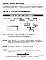
MB1000 Instructions
A Fully Programmable, Uninterruptible Power Supply, Voltage Regulator & Power Conditioner
Features:
• Surge Protection and AVM
• LiFT Noise Filtration
• Dual Learning IR Output Controls
• RS-232 with Open Source Code Protocol
• Fully Programmable
• Power Management Software Included
• USB Interface
• Critical Load Management
• USB Cable Included
• Software CD Included
• RS232 Pin Cable Included
• Rack Ears Included
INS00851 REV A, ENGLISH 10/08

Table of Contents
Important Safety Instructions.............................................................................................................................................pg. 1
Installing Your UPS..............................................................................................................................................................pg. 2
Specications......................................................................................................................................................................pg. 2
Descriptions........................................................................................................................................................................pg. 3
Operating Modes and Set-up Mode Flowchart..............................................................................................................pgs. 4, 5, 6
Advanced Operation.......................................................................................................................................................pgs. 6, 7
RS-232 Comunnications Protocal & Command Set................................................................................pgs. 8, 9, 10, 11, 12
FCC Notice and Warranties...............................................................................................................................................pg. 13
In addition to this manual the box should contain the following:
MB1000
0 VOLTS IN
EST’D BATTERY: 60 MIN
1. UPS Unit
2. DB 9 Serial Cable
3. Rack Mounting Kit
4. Software CD
5. USB Cord
Before You Begin UNPACKING Inspect the UPS upon receipt.
® 2008 Panamax, Inc., 1690 Corporate Circle, Petaluma, CA 94954 • www.panamax.com • 707-283-5900 • Fax 707-283-5901

This manual contains important instructions that should be
followed during installation and maintenance of the UPS
and batteries.
Please read and follow all instructions carefully during
installation and operation of the unit. Read this manual
thoroughly before attempting to unpack, install, or operate.
CAUTION! The UPS must be connected to an AC power
outlet with fuse or circuit breaker protection.
DO NOT plug the machine into an outlet that is not
grounded. If you need to de-energize this equipment, turn
off and unplug the UPS.
CAUTION! DO NOT USE FOR MEDICAL OR LIFE
SUPPORT EQUIPMENT!
Panamax does not sell products for life support or medical
applications. DO NOT use in any circumstance that would
affect operation or safety of any life support equipment,
with any medical applications, or patient care.
CAUTION! The battery can energize hazardous live parts
inside even when the AC input power is disconnected.
1
Important Safety Instructions
CAUTION! To prevent the risk of fire or electric shock
install in a temperature and humidity controlled indoor area,
free of conductive contaminants. (Please see specifications
for acceptable temperature and humidity range).
CAUTION! To reduce the risk of electric shock, do not
remove the cover. No user serviceable parts inside.
CAUTION! To avoid electrical shock, turn off the unit and
unplug it from the AC power source before installing a
component.
CAUTION! DO NOT USE WITH OR NEAR AQUARI-
UMS! To reduce the risk of fire, do not use with or near
aquariums. Condensation from the aquarium can come in
contact with metal current contacts and cause the machine
to short out.
Note: AC Power management devices, such as a UPS, have
certain limitations with regard to reactive loads and wattage.
The MB1000 has a handling capacity of 1000VA or approxi-
mately 600 watts. Excessive power consumption beyond
these specifications can affect battery life and performance.
IMPORTANT!
For proper operation, the batteries in this UPS
need to be fully charged prior to installation.
To Charge Batteries: Plug this UPS into an AC
receptacle and allow the batteries to charge
completely (6-8 hours) before connecting
other equipment to it.
Battery replacement recommended every two years.
DO NOT ATTEMPT BATTERY REPLACEMENT!
Must be serviced only by a qualified service
technician. Contact Customer Service for
information at 800-472-5555
.

2
HARDWARE INSTALLATION GUIDE
1. Your new UPS may be used immediately upon receipt.
However, recharging the battery for at least four hours is recom-
mended to insure that the battery’s maximum charge capacity is
achieved. Charge loss may occur during shipping and storage.
To recharge the battery, simply leave the unit plugged into an
AC outlet. The unit will charge in both the ON as well as the OFF
position. If you wish to use the software, connect the enclosed
USB cable to the USB port on the UPS and an open USB port on
the computer.
2. With the UPS unit OFF and unplugged, plug your equipment
into the unit’s rear panel AC outlets. DO NOT plug a space heater,
vacuum cleaner, paper shredder or other large electrical device
into the UPS. The power demands of these devices will overload
and possibly damage the unit.
3. Plug the UPS into a 2 pole, 3 wire grounded receptacle (wall
outlet). Make sure the wall branch outlet is protected by a fuse
or circuit breaker and does not service equipment with large
electrical demands (e. g. refrigerator, copier, etc.) Avoid using
extension cords. If used, the extension cord must be UL or CSA
Listed, minimum 14 AWG, 3-wire grounded, and rated for 15
Amps.
Installing Your UPS
4. Press and hold the power switch for 2 seconds to turn the
UPS on. The display will say “Initializing”, followed by the
normal operation screen.
5. The rear panel circuit breakers will open and power to the
connected equipment will be turned OFF if an overload is
detected. To correct this, turn the UPS off, unplug at least one
piece of equipment, wait 10 seconds, check to make sure that the
circuit breakers are reset, and turn the unit on.
6. The UPS will automatically charge the battery whenever it is
plugged into an AC outlet.
7. To maintain optimal battery charge, leave the UPS plugged
into an AC outlet at all times.
Note: To store your UPS for an extended period, cover it and
store with the battery fully charged. Recharge the battery every
three months to ensure battery life.
Specifications
Input
Voltage..............................................................................85 – 137 Vac
Frequency..............................................................................57 – 63 Hz
AC Power
Current Rating................................................................................12 A
Surge Protection...................................................................900 Joules
Overvoltage Shutoff, fast rise.................................................150 ± 5 V
Overvoltage Shutoff, slow rise................................................132 ± 5 V
Undervoltage Shutoff................................................................90 ± 5 V
Automatic Voltage Regulation,
Sensitive Mode Capture Range.............................................98 – 135 V
Automatic Voltage Regulation,
Sensitive Mode Output Range................................................120 ± 5%
Automatic Voltage Regulation,
Standard Mode Capture Range............................................93 – 145 V
Automatic Voltage Regulation,
Standard Mode Output Range..............................................120 ± 10%
Bank 1 EMI Filtration......................................66dB Max, 100kHz-2MHz
Bank 2 EMI Filtration......................................66dB Max, 100kHz-2MHz
UPS Output
Voltage...................................................120 ± 5 V Simulated Sine Wave
Frequency..............................................................................60 Hz ± 1%
UPS Output Capacity...........................................1000VA 600W @ 0.6pf
UPS Backup Time...................................................3 minutes at full load
Transfer Time...............................................................................< 10ms

3
Basic Operation FRONT PANEL DESCRIPTION
BANKS WIRING
1 2
POWER MENU
MB1000
FAULT
NON CRITICAL
LOAD
CRITICAL
LOAD
BANK 1
BANK 2
12 A
MAIN
POWER
120 / 12A
IR OUT IR STATUS
IR1
IR2
RS-232
Power Switch
Press and hold the power
button for 2 seconds to turn
the UPS ON or OFF.
Menu Navigation Knob
Rotate clockwise to navigate
to the next screen, counter-
clockwise to return to the
previous screen, push to
select menu item.
IR Detector
IR Detector, for
sampling IR
remote control
signals.
Removable Battery
Access Panel
Easy to remove for
battery access and
replacement.
Status Display
LCD displays status and
menu navigation items
Outlet Bank 1 Indicator
Illuminated blue when outlet
bank 1 is switched on.
Outlet Bank 2 Indicator
Illuminated blue when outlet
bank 2 is switched on.
Line Fault Indicator
This LED will illuminate in red to warn the user that a wiring problem such as a bad/miss-
ing ground or reversed wiring exists within the AC receptacle. If illuminated, disconnect all
equipment and contact an electrician to insure outlet is properly wired.
Outlet Bank 1 - Critical Load
Outlets
Four battery powered, surge protected
and AVR outlets for critical-load equip-
ment insures temporary uninterrupted
operation of connected equipment
during a power failure.
Outlet Bank 2 - Non-Critical-
Load Outlets
Four battery powered, surge
protected and AVR outlets for
connected equipment insures
temporary uninterrupted op-
eration of connected equipment
during a power failure. These
outlets will shut off when the
batteries drain to a designated
level to reserve remaining bat-
tery charge from the critical load
outlets.
AC Power Cord
IR Control Section
Indicator LED’s – Indicates status
IR Output Jacks – Standard 1/8”
(3.5mm) mono jack for connection
to an IR flasher (IR flashers not
included)
Circuit Breakers for Overload
Protection
Resettable circuit breakers provide
optimal overload protection.
RS-232
Serial Communication Port
The serial port allows connection and communica-
tion between the UPS and an automation or com-
puter system. This allows the installer to program
a number of variables including the Critical Load
Battery Threshold. See the software documentation
for more information.
USB to Computer
Ground Lug

4
Operating Modes
Normal Operation (Utility Power) Mode
When connected to a live power source, the MB1000 provides
power and is ready to provide protection from under- and over-
voltages.
Rotate the navigation dial to scroll through the screens.
Automatic Voltage Regulation (AVR) Mode
Sensitive AVR: when receiving input voltages of 98 VAC – 135
VAC, the MB1000 supplies a regulated voltage of 120 VAC ± 5
VAC.
Standard AVR: when receiving input voltages of 93 VAC – 145
VAC, the MB1000 supplies a regulated voltage of 120 VAC ± 10
VAC.
OFF: AVR is disabled. No voltage correction.
UPS Mode
In the event of a loss of power to the unit, over-voltage, or
under-voltage, the MB1000 will function as a battery back-up. An
audible alarm will sound and the display will indicate the fault as
well as the number of minutes of battery life remaining.
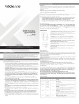
Setup Mode
The setup menu allows the user to adjust several of the operating
parameters of the unit.
Please refer to diagram (page 5) for a detailed map of the menu
structure.
Setup Menu Navigation
Clockwise (CW) rotation of the navigation dial advances the
menu to the next item. If the menu is at the last item, SYSTEM
INFO, return to Normal Operation Mode.
Counter clockwise (CCW) rotation of the navigation dial sends
the menu to the previous item. If the menu is at the first item,
DISPLAY BRIGHTNESS, return to Normal Operation Mode.
Pressing the navigation dial selects the current menu item.
If there is no activity of the navigation dial for 60 seconds, the
menu will automatically return to Normal Operation Mode.
Parameter Selection and Adjustment
CW rotation of the navigation dial INCREASES the selected
parameter, or advances to the NEXT available value.
CCW rotation of the navigation dial DECREASES the selected
parameter, or goes back to the PREVIOUS value. Pressing the
navigation dial selects the current parameter value.
If there is no activity of the navigation dial for 60 seconds, return
to Normal Operation Mode.
If the BACK parameter is selected, return to the menu item selec-
tion.
Display Brightness
Display Brightness adjusts the brightness of the display back-
light.
Display Scroll Mode
If enabled, the display will automatically advance to the next
screen every 5 or 10 seconds.
Display Sleep Mode
With Display Sleep Mode enabled, the Display will go to the
lowest brightness setting (25%) after the designated time of
inactivity of the Navigation Dial {30 SEC, 60 SEC }.
The display will return to the set brightness level upon entering
Setup Mode, or UPS Mode.
FAULT
BATTERY: 15 MIN
UPS Mode Screen
120 VOLTS
NORMAL POWER
Normal Operation Screen
SETUP

5
Setup Mode Flowchart
SETUP MENU
DISPLAY
BRIGHTNESS
BRIGHTNESS
XXX
DISPLAY
SCROLL MODE
SCROLL MODE
XXX
DISPLAY
SLEEP MODE
SLEEP MODE
XXX
AUTO REGULATION
SETUP
AVR MODE
XXX
NON CRITICAL
BANK 2 SETUP
BANK 2 SHUTOFF
BATTERY XXX
IR1 SETUP
IR OUTPUT DELAY
XXX SEC
BUZZER MODE
XXX
PANAMAX MB1000
FIRMWARE REV A
IR1 TEST IR1 PROGRAM
IR1 SAMPLED
IR2 SETUP
IR OUTPUT DELAY
BUZZER MODE
UPS TEST RUN TEST? XXX
SYSTEM INFO
IR1 SAMPLE FAIL
Pass/
Fail
SEL
SEL
SEL
SEL
SEL
SEL
BACK
BACK
BACK
BACK
SEL
BACK
SEL
SEL
SEL
BACK
SEL
SEL
Fail
Pass
IR2 TEST IR2 PROGRAM
IR2 SAMPLED
IR2 SAMPLE FAIL
Pass/
Fail
SEL
Fail
Pass

6
Operating Modes
Automatic Regulation Setup
Setup for Automatic Voltage Regulation parameters.
Outlet Bank 2 Setup
Adjusts the battery charge threshold in which Outlet Bank 2 is
shut off to conserve power for the critical loads connected to
Outlet Bank 1.
If set to OFF, Outlet Bank 2 will shut off immediately when the
unit goes into UPS Mode.
IR1 Control Setup
IR1 Control Setup is a two-step process in which the IR remote
control signal is sampled, and tested by outputting the learned
signal on the output jack.
IR Output Delay
IR Output Delay is the time delay before outputting the IR signals
on the IR output jacks after the unit goes into UPS mode.
IR Output Delay time starts at 0 sec, incremented in 5 sec inter-
vals, with a maximum value of 60 sec.
Setup Buzzer Mode
Change the UPS BUZZER MODE to set it to on or off.
UPS Test Mode
UPS Test Mode places the unit in UPS Mode temporarily to
verify that the UPS inverter can adequately supply the connected
load.
System Info
Displays the brand, model number and firmware revision
A connection to a UPS can benefit projector bulbs, server based
products, and units with volatile electronic memories found in
but not limited to Pro Audio, Broadcast and High-End Home
Theater equipment. The MB1000 takes this to the next level with
a number of features designed specifically for AC Power back up
applications.
Critical Load Function
One of the user programmable settings in the MB1000 software
is the Low Battery Non-Critical Load (NCL) Shutoff threshold.
This sets the battery capacity level at the point where the NCL
outlets are turned off and all remaining battery power is reserved
for equipment plugged into the 4 critical load outlets. This value
is stored internally by the UPS and is not dependent on having
the software running on a computer.
Patent-pending Learning IR Control
The learning IR function lets you program the UPS to send
standby or shut-down commands to components such as DLP
ceiling projectors. If the power fails, the projector’s lamps are
turned off while the UPS continues providing battery power to
the projector’s cooling fan. Proper shutdown is ensured and
expensive lamps are protected from damage.
Note: This function should only be used with discrete IR codes.
Programming an On/Off toggle command could result in the
equipment being turned ON during a power failure!
IR Power Failure Operation
The UPS can learn two IR commands. The learned commands
will be transmitted on both output jacks so you have the ability to
control 2 different pieces of equipment or use a 2-step macro for
one component.
1. After a power failure and the selected delay, the IR codes will
be sent to both outputs. The IR LED’s will flash once per second
during the delay time and will stop flashing after the IR code is
sent.
Advanced Operation

7
2. If the delay settings are the same for both IR1 and IR2, the IR2
code will be sent to both outputs 2 seconds after IR1.
3. The IR commands will also be transmitted immediately after
the battery charge falls below the critical load battery threshold.
This ensures that equipment will be shutdown properly if the
UPS’s load level is extremely high and the backup time would be
less than the selected IR output delay.
4. There is no IR output after the power is restored to the system.
To program IR output:
1. From the setup menu, turn the Menu Navigation Knob until
IR1 Setup is displayed. Push the Menu Navigation Knob to
select.
2. Turn the Menu Navigation Knob until IR1 Program is dis-
played.
3. The screen will display the message “READY TO SAMPLE
REMOTE”. Press the button on the remote.
4. If the signal was learned, then the screen will display the
message “IR1 SAMPLED” and advance to the “TEST IR” screen.
Press the navigation knob to test.
5.If the signal was not learned, the screen will display the mes-
sage “IR1 SAMPLE FAIL”, then it will return to the IR1 Program
screen. Repeat steps 3 and 4.
6.To program another IR device, from the Setup menu, turn the
Menu Navigation Knob until IR2 Setup is displayed. Follow
steps 3-5.
Advanced Operation
RS-232 Control with Open Protocol
The RS-232 serial interface can be used in the following ways:
1. Initial system setup. An installer can use a notebook comput-
er to set the variables within the Power Control software. Once
the setup is completed, the notebook computer can be discon-
nected. All settings are stored in the UPS.
2. Connection to a PC or Network: Functionality is very similar
to a standard UPS with a PC.
The UPS can provide continued power to maintain recording
capabilities of any number of devices in the event of a black out
or brown out. It is also capable of saving open documents and
shutting down the PC during extended power failures. This re-
quires a permanent RS232 connection to the PC and having the
Power Control software running in the background on the PC.
(Windows based OS only; Mac Energy Saver software compat-
ible)
3. Integration with sophisticated automation systems like AMX
and Crestron:
The serial communications command set and protocol is open
and is published later in this manual. This information can be
used by the automation system programmer for both UPS control
by the automation system and reporting of power events by the
UPS to the automation system.
RS-232 Communications Protocol &
Command Set

8
Communications Protocol
Connector Pin-out:
Pin 2, Transmit. The MB1000 transmits data on this pin.
Pin 3, Receive. The MB1000 receives data on this pin.
Pin 5, SG (signal ground).
Baud Rate: 2400bps
Start Bits: 1
Data Bits: 8
Stop Bits: 1
Parity: None
Flow Control: None
Controller Commands
Commands and responses are in the form of ASCII character
strings terminated with a carriage return <CR> ASCII character
13 (hex).
If the state variable LINEFEED MODE = ON, a linefeed charac-
ter (<LF>, 0Ah, 10d) will follow the carriage return.
Incoming messages (to the MB1000) shall be terminated with
one of the following characters: NUL (00h, 00d),
carriage return (<CR>, 0Dh, 13d) or line feed (<LF>, 0Ah, 10d).
The MB1000 shall discard the incoming message under the fol-
lowing conditions:
The message overruns the receiver buffer (32 characters).
No terminating character (NUL, <CR>, <LF>) is received within
500ms of receipt of the last character.
The following are commands sent by the controlling equipment
to the MB1000.
Note: Responses are only transmitted if unsolicited feedback is
enabled (!SET_FEEDBACK)
ALL ON
Turns on all outlets. Turn on is immediate with no delay.
Send to UPS: !ALL_ON<CR>
_____________________________________________
If power is not switched off due to low battery conditions:
Action: Turn on Outlet Bank 1
Response from UPS: $BANK 1 = ON<CR>
_____________________________________________
If UPS battery level > Shutoff Threshold
Action: Turn on Outlet Bank 2
Response from UPS: $BANK 2 = ON<CR>
_____________________________________________
If UPS battery level < Shutoff Threshold
Action: Turn off Outlet Bank 2
Response from UPS: $BANK 2 = OFF<CR>
$BATTERY = charge%<CR>
_____________________________________________
Action: Activate Power Button
Response from UPS: $BUTTON = ON<CR>
_____________________________________________
ALL OFF
Turns off all outlets. Turn off is immediate with no delay.
Send to UPS: !ALL_OFF<CR>
Action: All outlets will turn off
Response from UPS: $BANK 1 = OFF<CR>
Response from UPS: $BANK 2 = OFF<CR>
Response from UPS: $BUTTON = OFF<CR>
RS-232 Communications Protocol & Command Set
Pin 2 -Transmit
Pin 3 - Receive Pin 3 - Receive
Pin 2 -Transmit
1
6
2
7
3
8
4
9
5
1
6
2
7
3
8
4
9
5
Pin 5 - Signal Ground
RS232 Pin-out

9
RS-232 Communications Protocol & Command Set
SWITCH OUTLET BANK
Turns a specific outlet bank on or off. Switching is immediate
with no delay.
Send to UPS: !SWITCH bank state<CR>
bank = {1, 2}
state = {ON, OFF}
Example: !SWITCH 2 ON<CR> (turns on outlet bank 2)
_________________________________________
If power to bank 1 is switched:
Action: Switch power to Outlet Bank 1
Response from UPS: $BANK 1 = state<CR>
_________________________________________
If power to bank 2 is switched AND battery level > Shutoff Threshold:
Action: Switch power to Outlet Bank 2
Response from UPS: $BANK 2 = state<CR>
_________________________________________
If UPS battery level > Shutoff Threshold
Action: Turn on Outlet Bank 2
Response from UPS: $BANK 2 = ON<CR>
_________________________________________
If UPS battery level < Shutoff Threshold
Action: Turn off Outlet Bank 2
Response from UPS: $BANK 2 = OFF<CR>
$BATTERY = charge%<CR>
_________________________________________
If power button is OFF and state is changed to ON
Action: Activate Power Button
Response from UPS: $BUTTON = ON<CR>
_________________________________________
If entered bank or state are invalid
Response from UPS: $INVALID_PARAMETER<CR>
SET BANK 2 THRESHOLD
Sets the battery level threshold in which Outlet Bank 2 shuts off.
Send to UPS: !SET_BATTHRESH level<CR>
level is a number between 20 and 100 represents the bat-
tery charge level where Outlet Bank 2 is shut off to the reserve
remaining battery charge for the equipment connected to Outlet
Bank 1. level shall be rounded up to the nearest interval of 10.
If level is >19 AND level <101
Action: SHUTOFF THRESHOLD will be set
to a value between 20 and 100
Response from UPS: $BTHRESH = level<CR>
_________________________________________
If specified level is invalid
Action: No action will be taken
Response from UPS: $INVALID_PARAMETER<CR>
_________________________________________
SET BUZZER MODE
With Buzzer Mode ON, the buzzer will sound during UPS Mode.
Send to UPS: !SET_BUZZER mode<CR>
mode = {ON, OFF}
_________________________________________
If specified mode is invalid
Action: No action will be taken, UPS will
request a valid mode setting
Response from UPS: $INVALID_PARAMETER<CR>
$BUZZER = mode<CR>
_________________________________________

10
RS-232 Communications Protocol & Command Set
SET AVR MODE
Sets AVR (Automatic Voltage Regulation) MODE.
Command: !SET_AVR mode<CR>
mode = {OFF, STANDARD, SENSITIVE}
_________________________________________
If specified mode is invalid
Action: No action will be taken, UPS will
request a valid mode setting
Response from UPS: $INVALID_PARAMETER<CR>
$AVR = mode <CR>
_________________________________________
SET FEEDBACK MODE
Sets the feedback mode to ON (unsolicited) or OFF (polled).
When ON, a message will be sent to the controller every time the
status of an input (i.e. button), output (i.e. outlet) or power state
(i.e. overvoltage) changes.
If feedback is OFF, the controller must request status with a query
(see Queries section for more details).
Send to UPS: !SET_FEEDBACK mode<CR>
mode = {ON, OFF}
_________________________________________
If specified mode is invalid
Action: No action will be taken, UPS will
request a valid mode setting
Response from UPS: $INVALID_PARAMETER<CR>
$FEEDBACK = mode<CR>
_________________________________________
SET LINEFEED MODE
With LINEFEED MODE set, a linefeed character (<LF>, 10d, 0Ah)
is appended to each response.
Send to UPS: !SET_LINEFEED mode<CR>
mode = {ON, OFF}
_________________________________________
If specified mode is invalid
Action: No action will be taken, UPS will
request a valid mode setting
Response from UPS: $INVALID_PARAMETER<CR>
$LINEFEED = mode<CR>
_________________________________________
SET METER BRIGHTNESS
Sets the LCD display and outlet bank indicator brightness.
Send to UPS: !SET_BRIGHT xxx<CR>
xxx = {100, 075, 050, 025}
_________________________________________
If specified brightness setting is invalid
Action: No action will be taken, UPS will
request a valid brightness setting
Response from UPS: $INVALID_PARAMETER<CR>
$BRIGHTNESS = xxx<CR>
_________________________________________
SET DISPLAY SCROLL MODE
Sets the LCD display SCROLL mode
Send to UPS: !SET_SCROLLMODE xxx<CR>
xxx = {5SEC, 10SEC, OFF}
_________________________________________
If specified display scroll mode is invalid
Action: No action will be taken, UPS will
request a valid mode setting
Response from UPS: $INVALID_PARAMETER<CR>
$SCROLL_MODE = xxx<CR>
_________________________________________
SET DISPLAY SLEEP MODE
Sets the LCD display SLEEP mode
Command: !SET_SLEEPMODE xxx<CR>
xxx = {30SEC, 60SEC, OFF}
If specified display sleep mode is invalid
Action: No action will be taken, UPS will
request a valid mode setting
Response from UPS: $INVALID_PARAMETER<CR>
$SLEEP_MODE = xxx<CR>
_________________________________________

11
RS-232 Communications Protocol & Command Set
RESET FACTORY SETTINGS
Resets all of the custom configuration settings
Send to UPS: !RESET_ALL<CR>
Action: Sets all state variables to the default
values
Response from UPS: $FACTORY SETTINGS
RESTORED <CR>
_________________________________________
QUERIES
IDENTIFY
Request that the unit identify itself.
Send Query to UPS: ?ID<CR>
Action: Model number and firmware revision
will be provided.
Response: $PANAMAX<CR>
$MB1000<CR>
$FIRMWARE revision<CR>
_________________________________________
OUTLET STATUS
Requests the on/off status of the outlet banks
Send Query to UPS: ?OUTLETSTAT<CR>
status = {ON, OFF}
Action: On/Off status for outlets
will be provided.
Response: $BANK1 = status<CR>
$BANK2 = status<CR>
_________________________________________
POWER STATUS
Requests the status of the input voltage. The responses are the
same as Power Fault Status Change.
Send Query to UPS: ?POWERSTAT<CR>
Action: Power status messages will be
returned
Response: Normal operation $PWR =
NORMAL<CR>
Overvoltage $PWR = OVERVOLTAGE<CR>
Undervoltage $PWR = UNDERVOLTAGE<CR>
Lost Power $PWR = LOST POWER<CR>
Test Mode $PWR = TEST<CR>
_________________________________________
VOLTAGE
Requests the input and output voltages
Send Query to UPS: ?POWER<CR>
Action: Voltage status messages will be
displayed
Response: $VOLTS_IN = vvv<CR>
$VOLTS_OUT = vvv<CR>
$WATTS = xxxx<CR>
$VA = xxxx<CR>
xxx is expressed in decimal format. If the value is less than 100,
the hundreds digit is represented with a 0. For example a line
voltage of 92VAC would be expressed as: $VOLTAGE =092
_________________________________________
LOAD LEVEL STATUS
Requests the load level, expressed as percentage of maximum.
Send Query to UPS: ?LOADSTAT<CR>
Action: Load level will be displayed
Response: $LOAD = xxx<CR>
xxx is the load level (percentage of maximum load) expressed in
decimal format. If the value is less than 100, the hundreds digit
is represented with a 0.
_________________________________________

12
RS-232 Communications Protocol & Command Set
BATTERY LEVEL STATUS
Requests the battery level, expressed as a percentage of maxi-
mum (full charge).
Send Query to UPS: ?BATTERYSTAT<CR>
Action: Load level will be displayed
Response: $BATTERY = xxx<CR>
xxx is the battery charge level (percentage of maximum charge)
expressed in decimal format. If the value is less than 100, the
hundreds digit is represented with a 0.
____________________________________________
LIST CONFIGURATION
Requests a list of all configurable parameters and current settings.
Send Query to UPS: ?LIST_CONFIG<CR>
Action: List of configurable parameters and
current settings will be displayed.
Response: $BTHRESH = level<CR>
$BUZZER = mode<CR>
$AVR = mode<CR>
$FEEDBACK = mode<CR>
LINEFEED = mode<CR>
$BRIGHTNESS = xxx<CR>
$SCROLL_MODE = xxx<CR>
$SLEEP_MODE = xxx<CR>
____________________________________________
List of all commands and queries
Send Query to UPS: ?HELP<CR>
Action: List of all commands and queries
will be displayed
Response: !ALL_ON<CR>
!ALL_OFF<CR>
!SWITCH<CR>
!SET_BATTHRESH<CR>
!SET_BUZZER<CR>
!SET_AVR<CR>
!SET_FEEDBACK<CR>
!SET_LINEFEED<CR>
!RESET_ALL<CR>
!SET_BRIGHT<CR> ?VOLTAGE<CR>
!SET_SCROLLMODE<CR> ?LOADSTAT<CR>
!SET_SLEEPMODE<CR> ?BATTERYSTAT<CR>
?ID<CR> ?LIST_CONFIG<CR>
?OUTLETSTAT<CR> ?HELP<CR>
?POWERSTAT<CR>
_________________________________________
RESPONSES & MESSAGES
OUTLET STATUS CHANGE
CONDITION RESPONSE
Outlet Bank 1 changes state $BANK1 = status<CR>
Outlet Bank 2 changes state $BANK2 = status<CR>
status = {ON, OFF}
_________________________________________
POWER BUTTON STATUS CHANGE
CONDITION RESPONSE
Power Button changes $BUTTON = status<CR>
ON/OFF status
status = {ON, OFF}
_________________________________________
POWER FAULT STATUS CHANGE
CONDITION RESPONSE
Overvoltage State $PWR = OVERVOLTAGE<CR>
Undervoltage State $PWR = UNDERVOLTAGE<CR>
Lost Power State $PWR = LOST POWER<CR>
Test Mode $PWR = TEST<CR>
Recovery Mode $PWR = RECOVERY<CR>
Normal Operation Mode $PWR = NORMAL<CR>
Low Battery $LOWBAT<CR>
AVR Stage $AVRSTATE = state<CR>
state = {BOOST, BUCK}
Remaining Backup Time $TIME = xxx<CR>
xxx = backup time
Battery State $BATTSTATE = xxx<CR>
xxx = {CHARGE, DISCHARGE, FULL}
Power Control Software
Complete Instructions are available by clicking on Help on the
Power Control Software welcome screen.

13
® 2008 Panamax, Inc., 1690 Corporate Circle, Petaluma, CA 94954 • www.panamax.com • 707-283-5900 • Fax 707-283-5901
FCC Notice and Warranties
FCC Notice
This equipment has been tested and found to comply with the limits for a
Class B Digital Device, pursuant to Part 15 of the FCC Rules. These limits
are designed to provide reasonable protection against harmful interference
in residential installation. This equipment generates, uses, and can radiate
radio frequency energy and, if not installed and used in accordance with
the instructions, may cause harmful interference to radio communications.
However, there is no guarantee that interference will not occur in a particu-
lar installation. If this equipment does cause harmful interference to radio
or television reception, which can be determined by turning the equipment
off and on, the user is encouraged to try to correct the interference by one
or more of the following measures:
(1) Reorient or relocate the receiving antenna.
(2) Increase the separation between the equipment and receiver.
Warning Notice
WARRANTY LIMITATION FOR INTERNET PURCHASERS
Panamax products purchased through the Internet do not carry a valid
Connected Equipment Protection Policy unless purchased from an Au-
thorized Panamax Internet Dealer! Authorized Panamax Internet Dealers
have sufficient expertise to insure warranty compliant installations. For
a list of Authorized Panamax Internet Dealers go to www.panamax.com.
CAUTION: Audio/Video, computer and/or telephone system installa-
tions can be very complex systems, which consist of many intercon-
nected components. Due to the nature of electricity and surges, a single
protector may not be able to completely protect complex installations.
In those cases, a systematic approach using multiple protectors must
be employed. Systematic protection requires professional design. AC
power, satellite cables, CATV cables, A/V signal line cables or tele-
phone/network lines entering the system that do not pass through a
Panamax surge protector will render the Panamax connected equipment
protection policy null and void. For additional information on how to
protect your system, please contact Panamax before connecting your
equipment to the surge protector.
More detailed information is available at www.panamax.com.
If you have any questions regarding these requirements, please contact
Customer Relations.
(3) Connect the equipment into an outlet on a circuit different from that to
which the receiver is connected.
(4) Consult the dealer or an experienced radio/TV technician for help.
Any special accessories needed for compliance must be specified in the
instruction.
CAUTION: A shielded-type power cord is required in order to meet FCC
emission limits and also to prevent interference to the nearby radio and
television reception. It is essential that only the supplied power cord be
used. Use only shielded cables to connect I/O devices to this equipment.
CAUTION: Any changes or modifications not expressly approved by
the guarantee of this device could void the user’s authority to operate the
equipment.
LIMITED PRODUCT WARRANTY
Panamax warrants to the purchaser of this Panamax audio/video
component style uninterruptible power supply, for a period of three (3)
years from the date of purchase, that the unit shall be free of defects in
design, material, or workmanship, and Panamax will repair or replace
any defective unit.
Panamax Power Conditioner Limited Product Warranty
Panamax warrants to the purchaser of this Panamax audio/video com-
ponent style power conditioner, for a period of three (3) years from the
date of purchase, that the unit shall be free of defects in design, material
or workmanship, and Panamax will repair or replace any defective unit.
Upgrade Policy
Valid only in the United states and Canada
If your Panamax UPS sacrifices itself while protecting your connected
equipment, you have an option to upgrade to the latest technology.
Please go to our web sites www.panamax.com or contact Customer
Relations at 800-472-5555 for details.
2 Year Battery Warranty
Please contact Panamax Customer Service for information regarding
battery replacement and 2-year Battery Warranty.
INS00851 REV A, ENGLISH 10/08

5
Mode de configuration
SETUP MENU
DISPLAY
BRIGHTNESS
BRIGHTNESS
XXX
DISPLAY
SCROLL MODE
SCROLL MODE
XXX
DISPLAY
SLEEP MODE
SLEEP MODE
XXX
AUTO REGULATION
SETUP
AVR MODE
XXX
NON CRITICAL
BANK 2 SETUP
BANK 2 SHUTOFF
BATTERY XXX
IR1 SETUP
IR OUTPUT DELAY
XXX SEC
BUZZER MODE
XXX
PANAMAX MB1000
FIRMWARE REV A
IR1 TEST IR1 PROGRAM
IR1 SAMPLED
IR2 SETUP
IR OUTPUT DELAY
BUZZER MODE
UPS TEST RUN TEST? XXX
SYSTEM INFO
IR1 SAMPLE FAIL
Pass/
Fail
SEL
SEL
SEL
SEL
SEL
SEL
BACK
BACK
BACK
BACK
SEL
BACK
SEL
SEL
SEL
BACK
SEL
SEL
Fail
Pass
IR2 TEST IR2 PROGRAM
IR2 SAMPLED
IR2 SAMPLE FAIL
Pass/
Fail
SEL
Fail
Pass

12
Protocole de communication et jeu de commandes RS-232
CHARGE DE LA BATTERIE
Pour demander la charge de la batterie, exprimée comme pourcentage
du maximum.
Envoyer la requête suivante à l’onduleur : ?BATTERYSTAT<CR>
Action : La charge de la batterie s’affiche.
Réponse : $BATTERY = xxx<CR>
xxx représente la charge de la batterie (en pourcentage de la charge
maximale) exprimée en format décimal. Si la valeur est inférieure à 100,
le chiffre des centaines est représenté par un zéro
________________________________________________
LISTE DES CONFIGURATIONS
Pour demander la liste de tous les paramètres configurables et leurs
configurations actuelles.
Envoyer la requête suivante à l’onduleur : ?LIST_CONFIG<CR>
Action : La liste des paramètres configurables et
leurs configurations actuelles s’affiche.
Réponse : $BTHRESH = level<CR>
$BUZZER = mode<CR>
$AVR = mode<CR>
$FEEDBACK = mode<CR>
LINEFEED = mode<CR>
$BRIGHTNESS = xxx<CR>
$SCROLL_MODE = xxx<CR>
$SLEEP_MODE = xxx<CR>
________________________________________________
Liste complète des commandes et requêtes.
Envoyer la requête suivante à l’onduleur : ?HELP<CR>
Action : La liste complète des commandes et
requêtes s’affiche.
Réponse : !ALL_ON<CR>
!ALL_OFF<CR>
!SWITCH<CR>
!SET_BATTHRESH<CR>
!SET_BUZZER<CR>
!SET_AVR<CR>
!SET_FEEDBACK<CR>
!SET_LINEFEED<CR>
!RESET_ALL<CR>
!SET_BRIGHT<CR> ?VOLTAGE<CR>
!SET_SCROLLMODE<CR> ?LOADSTAT<CR>
!SET_SLEEPMODE<CR> ?BATTERYSTAT<CR>
?ID<CR> ?LIST_CONFIG<CR>
?OUTLETSTAT<CR> ?HELP<CR>
?POWERSTAT<CR>
________________________________________________
RÉPONSES ET MESSAGES
CHANGEMENT D’ÉTAT DE LA PRISE
CONDITION RÉPONSE
L’état du bloc de prises 1 change $BANK1 = status<CR>
L’état du bloc de prises 2 change $BANK2 = status<CR>
status = {ON, OFF}
________________________________________________
CHANGEMENT D’ÉTAT DE L’INTERRUPTEUR
CONDITION RÉPONSE
Power Button changes $BUTTON = status<CR>
ON/OFF status
status = {ON, OFF}
________________________________________________
CHANGEMENT D’ÉTAT DU COURANT
CONDITION : RÉPONSE
Surtension $PWR = OVERVOLTAGE<CR>
Sous-tension $PWR = UNDERVOLTAGE<CR>
Courant interrompu $PWR = LOST POWER<CR>
Mode test $PWR = TEST<CR>
Mode de récupération $PWR = RECOVERY<CR>
Fonctionnement normal $PWR = NORMAL<CR>
Batterie faible $LOWBAT<CR>
Régulation automatique
de la tension $AVRSTATE = state<CR>
state = {BOOST, BUCK}
Remaining Backup Time $TIME = xxx<CR>
xxx = backup time
État de la batterie $BATTSTATE = xxx<CR>
xxx = {CHARGE, DISCHARGE, FULL}
Logiciel de gestion de l’alimentation
Les instructions complètes sont disponibles en cliquant sur Aide sur
l’écran de bienvenue du logiciel.

Tabla de contenido
Instrucciones de seguridad importantes...........................................................................................................pág. 1
Instalación del suministro de energía ininterrumpible (UPS)............................................................................pág. 2
Especicaciones...............................................................................................................................................pág. 2
Descripción.......................................................................................................................................................pág. 3
Modos de operación................................................................................................................................págs. 4, 5, 6
Operación avanzada......................................................................................................................................pág. 6, 7
Protocolo de comunicaciones RS-232 y conjunto de comandos...............................................págs. 8, 9, 10, 11, 12
Noticación de la FCC y garantías.....................................................................................................................pág. 13
In addition to this manual the box should contain the following:
MB1000
0 VOLTS IN
EST’D BATTERY: 60 MIN
1. Unidad de UPS
2. Cable serial DB 9
3. Juego de instalación en rack
4. CD de software
5. Cable USB
Before You Begin UNPACKING Inspect the UPS upon receipt.
® 2008 Panamax, Inc., 1690 Corporate Circle, Petaluma, CA 94954 • www.panamax.com • 707-283-5900 • Fax 707-283-5901

5
Configuración inicial
SETUP MENU
DISPLAY
BRIGHTNESS
BRIGHTNESS
XXX
DISPLAY
SCROLL MODE
SCROLL MODE
XXX
DISPLAY
SLEEP MODE
SLEEP MODE
XXX
AUTO REGULATION
SETUP
AVR MODE
XXX
NON CRITICAL
BANK 2 SETUP
BANK 2 SHUTOFF
BATTERY XXX
IR1 SETUP
IR OUTPUT DELAY
XXX SEC
BUZZER MODE
XXX
PANAMAX MB1000
FIRMWARE REV A
IR1 TEST IR1 PROGRAM
IR1 SAMPLED
IR2 SETUP
IR OUTPUT DELAY
BUZZER MODE
UPS TEST RUN TEST? XXX
SYSTEM INFO
IR1 SAMPLE FAIL
Pass/
Fail
SEL
SEL
SEL
SEL
SEL
SEL
BACK
BACK
BACK
BACK
SEL
BACK
SEL
SEL
SEL
BACK
SEL
SEL
Fail
Pass
IR2 TEST IR2 PROGRAM
IR2 SAMPLED
IR2 SAMPLE FAIL
Pass/
Fail
SEL
Fail
Pass
/