Page is loading ...

READ THOROUGHLY BEFORE INSTALLING
Save instructions for future use.
General:
Fixture access: To open, apply slight downward pressure to the
front of the door frame and pull latch. To close fixture, close door
until latch engages.
Mounting Plate Installations:
Install fixture onto sign structure and securely fasten using the
mounting plate/bracket.
Mounting Plate installation is for uplight only. Please call
manufacturer regarding other mounting options.
CAUTION
Unit will fall if not installed properly
• Follow installation instructions
WARNING
Risk of electric shock
• Turn power off before servicing
– see instructions
GENERAL
This luminaire is designed for use in outdoor applications and
should not be installed in areas of limited ventilation or in high
ambient temperature enclosures. This fixture should be installed
and maintained according to the following recommendations.
UNPACKING
This luminaire has been packed so that no parts should have
been damaged during transit. Inspect to confirm.
INSTALLATION
IMPORTANT: In order to provide a watertight seal, the
installer must seal the area around the knock-out holes, with
a type of caulking compound such as GE 100% silicone.
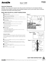
Slipfitter Installation:
Rout fixture leads through the Arm Fitting (provided by
others) connect to power leads (provided by others). Mount
fixture slipfitter to the Arm Fitting and secure by using (4) set
screws (provided) as illustrated in Figure 1.
If the Fixture is mounted in a position other than the horizon-
tal, use care that the lens door does not abruptly swing down and
injure someone. In order to mount at top of sign to be used as a
downlight, user needs to order fixture as a V3ST which includes
rain shield.
IMPORTANT: In order to comply with established electrical
code, the installer must seal the area around the Fixture Slipfitter
and the Arm Fitting, with a type of caulking compound such as
GE 100% silicone.
WIRING
For electrical connections, refer to wiring diagram on
ballast or HF generator.
Make all electrical connections in accordance with the
National Electrical Code and any applicable local code
requirements.
Verify that supply voltage is correct by comparing it to
nameplate.
GEH-5959C
Versaflood III
™
INSTRUCTIONS
Figure 1
Fixture Door
and Diffuser
Draw Pull
Latch (2)
Mogul Base
Socket
Socket Set
Screws (2)
Fixture Mounting Bracket
Silicone Sealant
J-Box
Black Wire
Ground Wire
White Wire
Wire Connectors (3)
Arm Fitting
(by others)
These instructions do not purport to cover all details or variations in equipment nor to provide for every possible contingency to be met in connection with installation, operation or
maintenance. Should further information be desired or should particular problems arise which are not covered sufficiently for the purchaser’s purposes, the matter should be referred
to GE Lighting Solutions.
g
GE
Lighting Solutions

Connect ground lead to the green lead, green ground
screw on housing or terminal block provided.
Do not remove insulated connectors from wires not needed
for required voltage connection.
IF SINGLE VOLTAGE:
All single voltage ballasts are pre-wired such that user need
only connect the supply conductors.
IF MULTIVOLT: (120/208/240/277 volts)
Connect the ballast lead with the insulated terminal to the
desired voltage terminal as indicated on the ballast terminal
nameplate.
MAINTENANCE
CAUTION
Risk of burn
• Allow lamp/fixture to cool before
handling
WARNING
Risk of burn
• Do not touch operating luminaire
It will occasionally be necessary to clean the outside of
the refractor to maintain the light level. Frequency of
cleaning will depend on the ambient dirt level and the
minimum light level which is acceptable to the user. The lens
door should be washed in a solution of warm water and any
mild, non-abrasive household detergent, rinsed with clean
water and wiped dry. Should the optical assembly become
dirty on the inside, wipe the reflector and clean the lens
door in the above manner and replace any damaged
gaskets.
Periodic cleaning on the outside of the door glass will
ensure operation at maximum optical efficiency. The glass
and reflector (if needed) should be cleaned with non-abrasive
soap, cleaner, or detergent solutions, rinsed with cold water
and wiped dry.
The light output is also dependent on the age of the
lamp. In applications where the light level is critical, it may
be desirable to replace lamps before they burn out. The lamp
manufacturer can provide data showing how the lamp light
output decreases with use.
LAMP INSTALLATION/REPLACEMENT
Use only lamps specified on nameplate. Observe lamp
manufacturer’s recommendations and restrictions on lamp
operation, particularly ballast type, burning position, etc.
Lamp Tightness – Mogul Base Lamp: The lamp should be
securely inserted to the NEMA-EEI specified torque of 35 inch-
pounds, which is best achieved by very firmly tightening to
insure application of sufficient torque. Tightening must be
sufficient to fully depress and load the center contact of the
socket.
QL induction lamps require assembly. Insert lamp onto
power coupler until lamp "clicks". Turn clockwise until second
"click" to lock.
NOTE: Lamp/coupler must be mounted on socket bracket
PRIOR to attaching to the reflector skirt.
Rain Shield Installation Instructions (for V3ST)
1. Silicone Seam Two Places
2. Place Rain Shield On Top Of Existing Fixture
3. Fasten with #10 Self Tapping Sheet Metal Screws Four Places
#10 SELF TAPING SHEET METAL SCREWS FOUR PLACES
RAIN SHIELD
SEAM TWO PLACES
FIRST STEP,
SLIP SHIELD THROUGH FITTER
(SEE BOTTOM ILLUSTRATION
BEFORE CONTINUING.)
FITTER
SECOND STEP,
INSTALL #10 SHEET METAL SCREWS IN TEN PLACES.
USE PRE-HOLES ON SHIELD.
(SEE BOTTOM ILLUSTRATION BEFORE CONTINUING.)
THIRD STEP,
SLIP FIXTURE ONTO MOUNTING
SHAFT AND FASTEN WITH SET
SCREWS AND THROUGH BOLT AS
ILLUSTRATED.
AFTER SLIPPING SHIELD ONTO FIXTURE FITTER, MAKE
SHIELD TANGENT TO FIXTURE IN THREE PLACES AS
SHOWN BELOW BEFORE FASTENING IN PLACE.
COMPLETE ASSEMBLED ILLUSTRATION
Dark Sky Shield Installation Instructions (for V3ST)
/