Page is loading ...

mase
GENERATORS
MANUALE USO E MANUTENZIONE
USAGE AND MAINTANCE MANUAL
MANUEL D’INSTRUCTIONS ET D’ENTRETIEN
GEBRAUCHSANWEISUNG UND WARTUNGSVORSCHRIFTEN
MANUAL USO Y MANTENIMENTO
GEBRUIKS- EN ONDERHOUDSHANDLEIDING
IS 8
IS 9.5
50 Hz
60 Hz
IS 9
IS 10.2
50 Hz
60 Hz
REV.4 M.C. 23-01-02 cod.41637

IS 8 - 9.5 9.2 - 10.2
2
mase
MASE GENERATORS S.p.A.
Tel.0547/354311
Fax 0547/317555 (commercial dept.)
Fax 0547/354314 (service dept.)
Fax 0547/317888 -Tlx 550397
NR.000000
DICHIARAZIONE CE DI CONFORMITA'
EC DECLARATION OF CONFORMITY
Fabbricante/Manufacturer: MASE GENERATORS S.p.A.
Indirizzo /Address : Via Tortona 345, Pievesestina (FO)
Il sottoscritto Luigi Foresti in qualità di direttore generale della MASE GENERATORS S.p.A., dichiara sotto la
propria responsabilità che il gruppo elettrogeno modello ......... :
The undersigned Luigi Foresti as MASE GENERATORS S.p.A. general manager declares, under his sole
responsability, that the generators model is..................:
Codice / Code Descrizione / Model Matricola / Serial N.
E' conforme alle disposizioni delle Direttive di seguito elencate :
CEE 89/392 (come emendata delle Direttive CEE 91/368 e CEE 93/44)
CEE 89/336 (come emendata delle Direttive CEE 92/31)
CEE 73/23 modificata da CEE 93/68.
Corresponds to the requirements of the following EEC Directives :
89/392/EEC (as amended by the Directive 91/368/EEC and 93/44/EEC)
89/336/EEC (as amended by the Directive 92/31/EEC )
73/23//EEC as amended by 93/68/EEC.
Cesena, / / ......................................................
Direttore Tecnico
Technical Director
GENERATORS
MASE GENERATORS S.p.A. Sede legale ed Amm.: 47023 CESENA (FO) ITALY - Via Tortona, 345 - C.F./P.I. 00687150409 Cap. Soc. milioni
1250 interamente versato - Registro Società Tribunale Forl' n. 6818 - CCIAA Forl' n.164063 - c.c.p. n. 11541471 - EXPORT FO n. 006368
1

IS 8 - 9.5 9.2 - 10.2
6
mase
1
1
TAB "A"
6
2
7
3
2
S.A.E
S
ervice
Grade
-30 -20 -10 0 10 20 30 4
0
Ambient temperature (
o
C)
8

IS 8 - 9.5 9 - 10.2
24
mase
GB
INDEX
THE GUARANTEE OF THE PRODUCT BECOMES VOID
IF THE SPECIFICATIONS CONTAINED IN THE
FOLLOWING INSTALLATION MANUAL ARE NOT
RESPECTED
Pictures .................................................................. 2
Wiring diagram ................................................ 9-10
1 General information ................................... 24
1.1 Purpose of the manual ................................... 24
1.2 Attached documentation ................................ 25
1.3 Machine identification .................................... 25
1.4 Instrument panel ............................................ 25
1.5 Safety regulations .......................................... 25
2 Generator description ................................. 26
2.1 General .......................................................... 26
2.2 Cooling system.............................................. 26
2.3 Control panel ................................................. 26
3 Using the generator .................................... 26
3.1 Preliminary checks ........................................ 26
3.2 Bleeding the fuel system ............................... 27
3.3 Starting .......................................................... 27
3.4 Stopping ........................................................ 27
4 Protections ................................................... 27
4.1 Low oil pressure protection ............................ 27
4.2 High water temperature protection ................. 27
4.3 Alternator overheating protection .................... 27
4.4 Alternator overheating protection .................... 28
4.5 Protection against short-circuit of the low-voltage
electric system .............................................. 28
5 Maintenance ................................................ 28
5.1 Ordinary engine maintenance ........................ 28
5.2 Engine oil and oil filter change ....................... 28
5.3 Air filter cleaning ............................................28
5.4 Fuel filter replacement ................................... 29
5.5 Coolant check................................................ 29
5.6 V-belt tension check ...................................... 29
5.7 Emptying the cooling system ........................ 29
5.8 Coolant replacement ...................................... 30
5.9 Zinc anode replacement ................................. 30
5.10 Seawater pump maintenance ........................ 30
5.11 Alternator maintenance .................................. 30
5.12 Battery maintenance ...................................... 30
5.13 Periods of inactivity ........................................ 30
5.14 Summary table of scheduled maintenance .... 31
5.15 Troubleshooting ............................................. 31
6 Technical characteristics ........................... 32
References for the wiring diagram .................... 33

IS 8 - 9.5 9 - 10.2
mase
25
GB
1. GENERAL INFORMATION
Carefully consult this manual before proceeding with any operation on the generator.
1.1 PURPOSE OF THE MANUAL
Thank you for choosing a MASE product.
This manual has been drawn up by the manufacturer and constitutes an integral part of the generator equipment. It must
be kept safely, protected from humidity and from any agent which might damage it, and must accompany the generator
if transferred to another user or to a new owner.
The information contained in the manual is addressed to all those persons involved in the operating life cycle of the
generator, and is useful for information for both those who effectively carry out the different operations and those who
coordinate the activities, arrange the necessary logistics and regulate access to the place of installation.
The manual defines the purpose for which the generator was constructed and contains all the information necessary
to guarantee safe and proper use.
Constant observance of the instructions contained in this manual guarantees the safety of the operator, operating
economy and a longer life of the generator.
To facilitate consultation, it has been divided into sections identifying the main concepts. For a quick look at the topics,
consult the index on Page 23.
Symbols
Those parts of the text not to be ignored are highlighted in bold type preceded by a symbol, as illustrated and defined
below:
Indicates that particular attention must be paid in order to prevent running into serious danger which
could lead to death of personnel or possible hazards to health.
A condition which may occur during the lifetime of a product, system or plant considered at risk
regarding damage to persons, property, the environment or economic loss.
Indicates that particular attention must be paid in order to prevent serious consequences which
could result in damage to tangible goods, such as the resources or the product.
Instructions of particular importance.
The drawings are provided by way of example. Even if the generator in your possession differs considerably from the
illustrations contained in this manual, the safety of the generator and the information provided are nevertheless
guaranteed.
The manufacturer in his pursuit of a policy of constant development and upgrading of the product may make any
modifications without prior notice.

IS 8 - 9.5 9 - 10.2
26
mase
GB
1.2 Attached documentation
The following documentation forms an integral part of
this manual:
- EEC declaration of conformity (Fig. 1)
- Engine use and maintenance manual
- Service logbook
- Certificate of guarantee
- Guarantee card
1.3 Machine identification
See Fig. 2
1 Machine code
2 Year of construction
3 Power factor
4 - Declared frequency
5 - Continuous power
6 Rated voltage
7 Current
8 Weight
9 Performance class
10 Serial number
The data identifying the machine code number, the serial
number and the year of construction must always be
specified when contacting the manufacturer for information
or for requests for spare parts.
See Fig. 3
1- Soundproof casing
2- Top access door
3- Side access door
4- Instrument panel
5- Anchoring brackets
6- Exhaust and cooling water pipe fitting
7- Seawater intake connection pipe fitting
8- Connection pipe fittings to fuel tank
9- Connection terminals to battery
10- Engine air filter
11- Coolant expansion tank
12- Engine oil extraction pump
13- Diesel fuel filter cartridge
14- Seawater pump
15- Fuel pump
16- Oil filter cartridge
17- Oil fillercap
18- Electric line connection box
19- Battery charger alternator
20- Coolant tank
21- Water/air heat exchanger
22- Exhaust manifold
23- Starter motor
1.4 Instrument panel
Legend Fig. 4
1- Hour counter
2- Magnetothermal switch
3- DC current thermal switch
4- START/STOP button
5- Engine protection module
6- RUN light engine running
7- OIL light low oil pressure
8- ºC light high engine temperature
9- BATT light battery charger operating
10- ºC light high alternator temperature
11- Glow plugs (not present)
12- Fuel leak (version RINA)
1.5 Safety regulations
Carefully read all the information contained in this manual
and the installation manual as it is fundamental for proper
installation and use of the generator and for timely
intervention in case of necessity.
The manufacturer declines all responsibility for damage
to persons or things deriving from inobservance of the
safety regulations.
Carefully examine the safety warning plates on the
machine and respect the relevant instructions.
- Do not permit incompetent persons or without
adequate training to use the generator.
- Do not permit children or animals to approach the
generator when it is in operation.
- Do not access the generator or the control panel with
wet hands, since it is a potential source of electric
shock if improperly used.
- Any inspections of the generator must be carried out
with the engine off. Inspections with the engine on are
to be carried out by specialised personnel only.
- Do not inhale the combustion smoke since it contains
substances hazardous to health.
- Use the generator with the access doors closed.
- Never touch the engine or alternator body with the
hands when the generator is running or still hot.
In the event of oil or fuel leaks, clean off thoroughly
to prevent creating fire hazard conditions.
In the event of fire, do not use water, but fire
extinguishers.
Should any problem arise or should you have any
questions, please contact the Mase SERVICE
department.

IS 8 - 9.5 9 - 10.2
mase
27
GB
2. GENERATOR DESCRIPTION
2.1 General
The IS 8 and IS 9.5 generators were designed for easy
installation on boats.
The soundproof casing, obtained with insulated, painted
marine aluminium panels, allows easy access to the
engine and the alternator for maintenance and inspection
operations, and at the same time strongly reduces noise.
The 4-stroke, direct-injection, diesel engine, built by
Yanmar, is extremely reliable and robust. Exhaust
emission is in conformity with CARB regulations.
The synchronous-type, 4-pole, brushless alternator has
an electronic voltage regulator (SR7) which guarantees
stability to + 5% with respect to the nominal value. The
high pickup capacity of the alternator makes the generator
particularly suitable for the power supply of electric
motors of air conditioners, desalination plants,
compressors, etc.
The generator has a local control panel [Fig. 3 Ref. 4] on
which the controls and control instruments are housed.
2.2 Cooling system
The generator engine is cooled by closed-circuit circulation
of coolant which yields heat to the seawater by means of
a heat exchanger [Fig. 3, Ref. 20].
This heat exchanger built of cupronickel was specially
designed by mase to make the engine suitable for use at
sea.
A second heat exchanger cools the air inside the soundproof
casing and the air necessary for alternator ventilation.
At the time of installation a seawater feed circuit for
cooling must be installed and an exhaust system to
convey the combustion gas and the water used for cooling
to the outside.
2.3 Control panel
A control panel is positioned on the generator for running
checks and to start and stop the generator. An engine
protection module [Fig. 4 Ref. 5] controls the generator
protections, stopping the engine in case of a fault and
signalling the fault detected by means of special warning
lights.
- Green RUN pilot light [Fig. 4 Ref. 6], when on,
indicates that the generator is running and no operating
fault has been detected.
- Red BATT pilot light [Fig. 4 Ref. 9), when on,
indicates that the alternator battery charger is faulty.
- Red OIL pilot light [Fig. 4 Ref. 7], when on, indicates
that the engine oil pressure is insufficient.
- Red [Fig. 4 Ref. 10] pilot light, when on, indicates that
the temperature of the coolant or the water circulating
in the heat exchangers is too high.
- Red [Fig. 4 Ref. 8] pilot light, when on, indicates that
the alternator windings have reached too high
temperatures.
The following may also be found on the control panel:
- A bipolar magnetothermal switch [Fig. 4 Ref. 2] which
cuts the power in case of an overload or short-circuit.
- A thermal switch (Fig. 4 Ref. 3] to protect the low-
voltage electric system against short-circuit.
- An hour counter (Fig. 4 Ref. 1].
- The generator start/stop button [Fig. 4 Ref. 4].
The generator can be connected with a connector to the
remote starting panel, supplied by mase as an optional,
and can be installed on the dashboard.
Two different remote starting panels are available as
shown in Fig. 5.
The most simple version has a start/stop button [Fig. 5
Ref. 1] and a green pilot light [Fig. 5 Ref. 2] which, when
on, indicates that the generator is running.
The second version of the remote starting panel [Fig. 5
Ref. 3] has, in addition to the start/stop button, an
instrument which indicates the engine oil pressure value
(Fig. 5 Ref. 4] and an instrument which indicates the
coolant temperature value [Fig. 5, Ref. 5].
When carrying out maintenance operations on the
generator, disconnect the negative pole of the starter
battery to prevent accidental starting.
3. USING THE GENERATOR
3.1 Preliminary checks
At first starting of the generator, or after having done any
type of maintenance work, it is always good practice to
check:
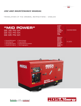
- the oil level by means of the dipstick [Fig. 7 Ref. 2]
(see table A for recommended oils [Fig. 8]).
- that all the anchoring points of the generator are
properly tightened.
- that all the electrical utilities are off to prevent starting
the generator on load
- that the water and fuel pipes are properly connected
- that all the electrical connections have properly been
carried out and that there are no electrical connections
in a bad state.
- that the water cock is open [Fig. 6 Ref. 2]
- that the section of the water circuit from the pump to
the valves has been filled manually if a non-return
valve has been mounted on the sea intake (as
recommended in the installation manual) [Fig. 4 Ref.
1].

IS 8 - 9.5 9 - 10.2
28
mase
GB
3.2 Bleeding the fuel system
The presence of air bubbles in the fuel system is caused
by irregular functioning of the engine or the incapacity to
reach the nominal number of revolutions. Air might enter
the fuel circuit through a not perfectly tight seal (pipes,
filters, tank) or when the fuel in the tank is at minimum
level. The fuel system has been designed in such a way
as to autonomously eliminate air bubbles that have
penetrated the circuit. Automatic bleeding is obtained by
activating the fuel pump for a few minutes before starting
the engine.
The fuel pump is activated by pressing the START button
for a second.
Should the engine still function irregularly after this
operation, consult a technician for a thorough inspection
of the fuel system.
3.3 Starting
Before starting the generator, ensure that the preliminary
checks described in paragraph 3.1 have been carried out.
Start the generator by pressing the START button located
on the control panel [Fig. 4 Ref. 4] and release it only when
the generator has started, taking care not to exceed 15
sec. for each attempt and respecting an interval of at least
30 sec. All the warning lights of the engine protection
module [Fig. 4, Ref. 5] will come on for a few seconds, and
if there are no engine or generator faults, only the green
RUN light [Fig. 4 Ref. 6] will remain on to indicate that the
generator has been started and that functioning is regular.
Repeated attempts at starting with negative outcome
may cause excess accumulation of water in the
exhaust system with possible serious damage to the
engine.
If it is difficult to start the engine, do not insist for too
long without first having closed the sea intake cock
[Fig. 6 Ref. 2].
3.4 Stopping
The generator is stopped by pressing the OFF button on
the control panel.
Before stopping the generator it is recommended to
let it run for a few minutes without drawing electric
current, in order to allow the engine and the
alternator to cool down.
4. PROTECTIONS
The IS 8 and IS 9.5 generators are equipped with a series
of protections which safeguard them against improper
use and operating problems.
When the generator stops because a protection has
intervened, on the engine protection module [Fig. 5, Ref.
5] of the control panel the warning light relative to the fault
will come on.
4.1 Low oil pressure protection
Intervenes switching off the generator when the engine oil
pressure is insufficient. Its intervention is signalled by the
OIL light [Fig., 4, Ref. 7] coming on. Normally it is
sufficient to top up with the lacking quantity of oil to be
able to restart the generator.
The low oil pressure protection does not give an
indication of the level of engine oil in the sump.
Therefore, check this level daily.
The engine functions properly if it does not exceed
an inclination of maximum 30º for less than 3
minutes, 25º without time limit, both on the
longitudinal and the transverse axis. If the engine is
operated at a greater inclination, the risk is insufficient
lubrication or aspiration of engine oil through the
air filter.
4.2 High water temperature protection
Intervenes switching off the generator when the engine
coolant temperature is too high or there is no circulation
of seawater.
Its intervention is signalled by the ºC light [Fig. 4, Ref.
10] coming on.
Only restart the generator after the cause of the fault has
been identified and removed.
4.3 Alternator overheating protection
Intervenes switching off the generator when there is a
thermal overload on the alternator.
Its intervention is signalled by the ºC light [Fig. 4, Ref.
8] coming on. The generator can be restarted after a few
minutes when the temperature of the alternator windings
has returned to normal values. It is, however, recommended
to find and remove the causes of the intervention.
In the event of one of the above described
protections intervening, after ascertaining and
removing the cause of the intervention, press the
STOP button to reset the control panel (otherwise
the signal would remain in memory preventing the
engine from starting).

IS 8 - 9.5 9 - 10.2
mase
29
GB
4.4 Protection against short-circuit and overload
The generator is protected against short-circuit and
overload. A bipolar magnetothermal switch [Fig. 4 Ref. 2]
cuts the supply of electric current when a short-circuit
occurs or when the electric current delivered exceeds the
nominal value.
Before restoring the contact by lifting the lever of the
magnetothermal switch, disconnect the utilities.
4.5 Protection against short-circuit of the low-
voltage electric system
In the event of a short-circuit in the low-voltage electric
system, a thermal switch [Fig. 4, Ref. 3] breaks the circuit
stopping the generator. In this case the warning lights of
the engine protection module will all be off and it will not
be possible to re-attempt starting.
Before restoring the electric circuit by pressing the button
located on the thermal switch [Fig. 4 Ref. 3], have a
specialised technician find and remove the cause of the
short-circuit.
5. MAINTENANCE
Any maintenance operation on the generator must
be carried out with the engine off after letting it cool
down sufficiently, and must be carried out by
authorised personnel.
Before accessing the generator, disconnect one
pole of the starter battery in order to prevent
accidental starting.
5.1 Ordinary engine maintenance
The periodic maintenance to be carried out on the engine
is listed in TABLE B.
For more detailed information consult the manual provided
with each generator by the engine manufacturer.
Check the oil level by means of the graduated
dipstick [Fig. 7, Ref. 2]. The level must always be
between the MAX and MIN notches on the dipstick
[Fig. 7 Ref. 1].
5.2 Engine oil and oil filter change
The engine oil sump capacity is 3.6 litres.
Top-ups and filling with engine oil is carried out through
the hole [Fig. 3, Ref. 17].
To change the oil in the oil sump, remove the dipstick [Fig.
7, Ref. 2] and operate the special extraction pump [Fig.
3, Ref. 12] after having removed the screw which
functions as plug.
It is recommended to drain the oil when it is still sufficiently
warm to flow easily.
For recommended oils see table A, Fig. 8.
The first engine oil change must be carried out after
50 hours of generator operation. For the second and
subsequent oil changes, every 200 hours is sufficient.
For more detailed information on engine lubrication,
consult the engine use and maintenance manual
attached to the generator.
Dispose of the used oil or fuel in an appropriate
manner as they are polluting products.
Take the used engine oil to special collection centres
responsible for disposal.
Avoid contact of engine oil with the skin. During
maintenance operations use gloves and protective
glasses.
In case of contact with engine oil, immediately and
thoroughly wash the affected part with soap and
water.
To replace the engine oil filter cartridge [Fig. 3, Ref. ?],
unscrew it from its support, using suitable tools normally
found on the market. Reposition the new cartridge, taking
care to lubricate the rubber ring gasket.
The first replacement must be carried out after 50 hours
of generator operation. For the second and subsequent
replacements, respect an interval of 400 hours.
For further information consult the engine use and
maintenance manual.
For the safety of the engine, use only original spare
parts.
When the operation has been completed, thoroughly
wipe off all oil and fuel from the engine parts.
5.3 Air filter cleaning
The generators of the IS series have a dry air filter which
prevents foreign bodies from entering the combustion
chamber. For its maintenance it is sufficient to clean the
filtering mass with diesel fuel once a year to remove nay
impurities.

IS 8 - 9.5 9 - 10.2
30
mase
GB
Dispose of the liquids used for air filter washing in an
appropriate manner. Take them to special collection
centres.
Any maintenance operation on the generator must
be carried out with the engine off after letting it cool
down sufficiently, and must be carried out by
authorised personnel.
Before accessing the generator, disconnect the
negative pole of the starter battery to prevent
accidental starting of the generator.
5.4 Fuel filter replacement
To guarantee long life and proper functioning of the
engine, it is extremely important to periodically replace
the fuel filter cartridge, respecting the frequency indicated
by the engine manufacturer as listed in the table in
Paragraph 5.12.
This operation is carried out in the following steps:
- Close the fuel cock [Fig. 3, Ref. 24]
- Completely unscrew the ring nut of the support [Fig.
3, Ref. 13]
- Remove the old cartridge and position the new one.
- For remounting repeat the operations in reverse
order.
When the filter has been replaced, bleed the fuel system
carrying out the operations described in Paragraph 3.2.
Avoid contact of the fuel oil with the skin. During
maintenance operations use gloves and protective
glasses.
In case of contact with fuel, immediately and
thoroughly wash the affected part with soap and
water.
When the operation has been completed, thoroughly
wipe off all traces of fuel and take the used cloths to
special collection centres.
5.5 Coolant check
Periodically check the coolant level in the closed-circuit
cooling system. The reference index for this check is
printed on the expansion tank [Fig. 3, Ref. 11]. If the level
is insufficient, pour coolant into the expansion tank,
taking care not to exceed the maximum level index.
Never open the cap of the expansion tank [Fig. 3,
Ref. 11] or coolant tank [Fig. 3, Ref. 20] when the
engine is hot to prevent dangerous coolant leaks.
5.6 V-belt tension check
A V-belt is used to transmit the rotary motion from the
drive shaft pulley to that of the seawater pump [Fig. 9 Ref.
1].
Excessive belt tension accelerates wear, while a slack
belt makes the pulleys idle and does not allow sufficient
water circulation.
Adjust the belt tension as follows:
Loosen the two adjusting screws [Fig. 9, Ref. 2] and move
the seawater pump outwards to increase the tension or
inwards to decrease it. Lock the screws and check the
tension.
The correct belt tension is such as to allow a yield of about
5 mm [Fig. 9] under a thrust force of 8 kg.
A second belt is used to transmit the rotary motion from
the drive shaft pulley to that of the closed-circuit coolant
pump and the battery charger DC alternator [Fig. 9 Ref.
3].
Adjust the belt tension as follows:
Loosen the adjusting screw [Fig. 9 Ref. 4] and move the
battery charger DC alternator [Fig. 9, Ref. 5] outwards to
increase the tension and inwards to decrease it.
The correct belt tension is such as to allow a yield of about
10 mm [Fig. 9] under a thrust force of 8 kg.
To prevent the belt from slipping, do not dirty it with
oil. Clean the belt with petrol if any oil is spilled.
Keep hands away from the V-belt or the pulleys
when the engine is running.
5.7 Emptying the cooling system
To carry out maintenance on the water/air exchanger or
on the cooling system the seawater must be drained from
the intake circuit. This operation is carried out as follows:
- Close the sea intake cock [Fig. 6, Ref. 2]
- Open the drain tap [Fig. 6, Ref. 3] until all the water
has run out
- Close the drain tap.
Reopen the seawater intake cock before starting the
generator.

IS 8 - 9.5 9 - 10.2
mase
31
GB
5.8 Coolant replacement
Yearly change the coolant in the closed-circuit cooling
system.
Connect a 20-30 cm long rubber tube [Fig. 10, Ref. 2] to
the drain tap [Fig. 10, Ref. 1] located on the engine base
to facilitate collection of the used coolant in a collection
receptacle [Fig. 10, Ref. 3]. Open the tap and completely
drain the closed-circuit cooling system.
When the operation has been completed, close the tap
and fill the circuit with new coolant.
Dispose of the used coolant in an appropriate manner
as it is a polluting product.
Take the used coolant to special collection centres
responsible for disposal.
5.9 Zinc anode replacement
To protect the water/air heat exchanger [Fig. 11, Ref. 1]
and the water/coolant heat exchanger [Fig. 11, Ref. 2]
against galvanic current, two sacrificial zinc anodes [Fig.
11, Ref. 4] have been inserted inside them. Periodically
check their state of wear and, if necessary, replace them
in order to prevent that the galvanic current irreparably
corrodes the heat exchanger. It is recommended to
check the zinc anodes at least once a month when the
generator is new to check how fast consumption is, to
then be able to act accordingly.
It is, however, opportune to replace the zinc anodes at
least once a year.
Fig. 11 shows the points where the zinc anodes are
positioned.
5.10 Seawater pump maintenance
At least once a year check the integrity of the rubber rotor
of the seawater pump [Fig. 12, Ref. 1].
Before opening the seawater pump to inspect the rotor,
drain the seawater from the cooling system as described
in Paragraph 5.7.
To access the rotor, remove the cover [Fig. 12, Ref. 2] and
with the aid of a pair of pliers extract the rotor pulling it out
with force. To remount a new rotor, repeat the operations
described above in reverse order.
5.11 Alternator maintenance
The alternator used on this model of generator is type
synchronous, self-energised, with electronic voltage
regulation. This model alternator, without manifold and
brushes, does not require particular maintenance
operations. The periodic checks and maintenance are
limited to removing any traces of damp and oxidation
which might damage it.
5.12 Battery maintenance
For starting all the generator models, it is recommended
to use an 80 A/h battery for ambient temperatures
exceeding 0ºC, and 100 A/h for lower temperatures.
Before installing a new battery it is important that it
undergoes a full charging cycle.
At least once a month check the level of the electrolyte
and, if necessary, top up with distilled water. If the
generator is not to be used for a long period, it is
recommended to disconnect the battery and store it in a
dry place at a temperature over 10ºC and to carry out a full
charging cycle once a month.
If the battery is left completely flat for long periods,
there is a risk of irreparably damaging it.
The positive terminal of the battery must be protected with
Vaseline to prevent corrosion and the formation of oxide.
For top-ups with sulphuric acid, ready solutions
must be used.
The battery top-up operations with distilled water or
with acid must be carried out with rubber gloves and
protective glasses to prevent accidental contact of
the sulphuric acid with the skin.
In the event of accidental contact, thoroughly wash
the part affected with soap and water and consult a
doctor.
Before recharging the battery check the level of the
electrolyte and, if necessary, fill up with distilled
water. This operation must be repeated when the
recharging cycle has been completed.
5.13 Periods of inactivity
Start up the generator at least once a month. If the
generator is not to be used for a long time, the following
operations must be carried out:
- Change the engine oil
- Replace the oil filter cartridge (see par. 5.2)
- Replace the fuel filter cartridge (see par. 5.4)
- Remove the injectors and pour 2 cc engine oil into
each cylinder and let the engine turn over a few times,
manually operating the drive shaft pulley. Remount
the injectors.
- Replace the zinc anodes (see par. 5.9)
- Through the seawater intake pipe aspirate some anti-
freeze whose function is to protect the heat
exchangers against low temperatures and to lubricate

IS 8 - 9.5 9 - 10.2
32
mase
GB
the seawater pump rotor and the metallic parts in the
cooling system.
- Disconnect the starter battery and store it in a dry
place (see par. 5.12)
- Disconnect the sea exhaust pipe from the engine
manifold.
- Clean the seawater filter.
- Close the seawater intake cock.
- Drain the seawater from the exhaust.
- Clean and lubricate the antisiphon valve, if installed
(siphon break).
5.14 Summary table of scheduled maintenance
OPERATION HOURS
Check engine oil level .................................... 10
Check coolant .................................................. 10
Check for oil leaks ........................................... 20
Check for fuel leaks......................................... 20
Check for coolant leaks .................................. 20
Adjust V-belt tension ...................................... 100
Check battery charger.................................... 100
Clean fuel filter ............................................... 200
Adjust belt tension .......................................... 200
*Change engine oil ........................................ 200
Check seawater pump rotor .......................... 400
Check engine rpm .......................................... 400
Check integrity of electrical connections ..... 400
Replace fuel filter ........................................... 400
* Replace oil filter........................................... 400
Check injectors ............................................... 400
Check injector timing ..................................... 400
Adjust play on intake/exhaust valve ............. 400
Check the fuel injection pump ..................... 1000
Check battery electrolyte level ................. monthly
Clean and deoxidise the metallic parts...... yearly
Clean air filter ............................................... yearly
Replace coolant completely ........................ yearly
Replace zinc anodes .................................... yearly
Carry out the first maintenance operation after 50
hours, subsequently according the required intervals.
5.15 Troubleshooting
The starter motor turns but the main engine does not
start
- Check that there is fuel in the tank (fill up)
- Check if the stop electromagnet is in the firing position
(consult Service Centre)
- Bleed the air bubbles from the fuel circuit (see par. 3.2)
The engine protection module is not activated when
the START button is pressed
- battery, and the electrical connections (reconnect).
- Check integrity of the battery (recharge or replace).
The generator switches off during the operating
period
- Check if a protection has been activated with the
relevant light coming on (remove the cause and retry
starting).
- Check if there is fuel in the tank (fill up).
There is a high grade of smoke at the engine
exhaust
- Check that the oil level in the sump does not exceed
the MAX index (restore level).
- Check that the generator is not in overload.
- Check calibration of the injectors (consult Service
Centre).
The engine runs irregularly
- Check the fuel filters (replace).
- Bleed the air bubbles from the fuel circuit (see par.
3.2).
The alternator voltage is too low
- Correct the voltage value acting on the electronic
regulator.
- Check the engine rpm (1560 rpm without utilities
connected).
- Voltage regulator broken (replace).
Starter battery flat
- Check the electrolyte level in the battery (restore the
level).
- Check functioning of the DC alternator.
- Check integrity of the battery.
The generator does not deliver power
- Check that the magnetothermal switch [Fig. 4, Ref.
2] is in the ON position. If not, contact an authorised
Service Centre.
TABLE B

IS 8 - 9.5 9 - 10.2
mase
33
GB
6. TECHNICAL CHARACTERISTICS
,6 ,6 ,6 ,6
50 Hz 60Hz 50 Hz 60Hz
Model
Type
Cylinders (nr.)
Cylinder block material
Bore (mm. - in.)
Stroke (mm.- in.)
Displacement (cc. - CID)
Power (hp) 11.5 16.2 14.8 17.8
RPM 1500 1800 1500 1800
Compression ratio
Combustion system
Engine head material
Speed governor
Lubrication system
Oil sump capacity with filter(l -gl)
Engine stop system
Fuel pump
Fuel pump discharge (cm. - ft)
Fuel consumption (l/h - gl/h) 2.9 - 0.64 3.4 - 0.75 3.2 - 0.7 3.6 - 0.75
Air intake (l/min. - gl/min.) 730 - 193 876 - 231 730 - 208 876 - 231
Starting battery (Ah-V)
Battery charger (Ah-V)
Starter (KW-V)
Max. inclination
Water pump flow (l/min. - gl/min.) 25 - 6.6 28 - 6.1 25 - 6.6 28 - 6.1
50 Hz 60Hz 50 Hz 60Hz
Type
Cooling
Voltage (V) 115 - 230 120 - 240 115 - 230 120 - 240
Frequency (Hz) 50 60 50 60
Amps 67.8 - 33.9 73.3 - 36.6 78.2 - 39.1 83.3 - 41.
6
Max. power (KW) 7.8 8.8 9 10
Continuous power (KW) 7.2 8.5 8.2 9.5
Power factor ( cos ø )
Insulating class
Voltage stability
Frequency stability
Diesel 4 stroke
3
Cast iron
18:1
Direct injection
Cast iron
Centrifugal mechanical
Synchronous, 4-poles,
brush less self-excited
electronic voltage regulation (AVR)
Air/water ( Intercooler W/A )
1
H
30°
70 - 12
40 - 12
1.2 - 12
5.2 - 1.2
Stop solenoid
Electric
70 - 2.3
Forced
82 - 3.2
84 - 3.4
1331 - 89.8
Yanmar 3TNE82
78 - 3.7
84 - 3.4
1204 - 73.45
Yanmar 3TNE78A
±2%
±5%

IS 8 - 9.5 9 - 10.2
34
mase
GB
References for the wiring diagram
(Page 9 - Pict. 13 standard connection
Page 10 - Pict. 14 isolated poles connection )
1 Magnetothermal switch
2 Hour counter
3 Alternator
4 Stator
5 Exciter
6 Electronic voltage regulator
7 Thermal switch
8 Engine protection module
9 START/STOP button
10 Fuel level gauge
11 Oil pressure gauge
12 Water temperature gauge
13 Fuel pump
14 High water temperature sensor
15 High coolant temperature sensor
16 Oil pressure switch
17 DC alternator
18 Stop electromagnet
19 Starter motor
20 Battery connection terminals
21 Oil pressure gauge instrument
22 Coolant temperature gauge instrument
23 START/STOP button
24 Remote control panel connection cable
25 Connector for remote control panel connection
26 Remote control panel
27 Remote control panel
28 Earth relais
29 Stator
30 Starting Relay

IS 8 - 9.5 9.2 - 10.2
mase
79
Rev. / Rel.
FIG.
1 / 7
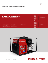
IS 8 - 9.5/ 9 - 10.2
MOTORE
ENGINE

IS 8 - 9.5 9.2 - 10.2
80
mase
Rev. / Rel.
FIG.
5LI &RG 4W\ 'HVFUL]LRQH 'HVFULSWLRQ
1 81078 1
MOTORE YANMAR 3TNE78A MG
ENGINE YANMAR 3TNE78A MG 50Hz
1 81127 1
MOTORE YANMAR 3TNE78 MG EPA
ENGINE YANMAR 3TNE78A MG 60Hz EPA
1 81214 1
MOTORE YANMAR 3TNE 82A MG
ENGINE YANMAR 3TNE82A MG 50Hz
1 81215 1
MOTORE YANMAR 3TNE 82A-EMG EPA
ENGINE YANMAR 3TNE82A EMG 60Hz EPA -
2 62319 2 STAFFA FISSAGGIO GRUPPO BRACKET
3 62317 2 STAFFA DX/SX SUPPORTO ALTERNATORE RH/LH BRACKET ALTERNATOR SUPPORT
4 62318 2 STAFFA SX/DX SUPPORTO MOTORE RH/LH BRACKET ENGINE SUPPORT
5 70309 4 ANTIVIBRANTE D50X30 SHOCK ABSORBER
6 010952 1 STAFFA SUPPORTO POMPA OLIO BRACKET OIL PUMP SUPPORT
7 20250 1 POMPA RICAMBIO OLIO 3/4" OIL DRAINAGE PUMP
8 10791 9 FASCETTA D.8/16 H9 CLAMP D.8/16 H9
9 70198 mt.0,35 TUBO CARBURANTE D.10X17 FUEL PIPE D.10X17
10 10785 2 RONDELLA D22 WASHER D.22
11 11203 1 RACC. AD OCCHIO D.22 PORTAGOM.D.13 UNION D.22
12 10581 1 VITE FORATA M22X1,5 HOLLOW SCREW M22X1,5
13 011084 1 KIT TRASMETTITORI OLIO ACQUA OIL WATER TRANSMITTER KIT
13A 11290 1 RACC.3VIE TRASMETTITORI PRESS.OLIO OIL WATER TRANSMITTER UNION
13B 32235 1 TRASMETTITORE VDO 1/8" 5 BAR TRANSMITTER VDO 1/8" 5 BAR
13C 32234 1 TRASMETTITORE VDO 16X1,5 120° TRANSMITTER VDO 16X1,5 120°
14 92682 1 PRESSOSTATO OLIO LOW OIL PRESSURE SWITCH
15 92640 1 TERMOCONTATTO THERMOSTAT
16 11286 1 RACCORDO 3 VIE 1/8" F. UNION
17 11278 1 RACCORDO D.5 X 1/8" M. UNION
18 11285 2 RACCORDO PORTAGOMMA 1/8" D.7 UNION
19 31004 1 POMPA PIERBURG 7.21440.03 PIERBURG PUMP
20 71059 1 VASO ESPANSIONE + TAPPO SUB-TANK + PLUG
21 010664 1 STAFFA SUPPORTO FILTRO NAFTA FUEL FILTER BRACKET SUPPORT
22 11280 2 RACC. OCCHIO D.12 PORTAGOM. D.8 UNION
23 10817 1 RACC. OCCHIO D.14 PORTAGOM. D.8 UNION
24 11282 1 RACC. OCCHIO D.8 PORTAGOM. D.6 UNION
25 910280 2 RONDELLA WASHER
26 910281 1 VITE FORATA HOLLOW SCREW
27 910282 1 VITE FORATA HOLLOW SCREW
28 910283 2 VITE FORATA HOLLOW SCREW
29 910284 2 RONDELLA WASHER
30 910232 4 RONDELLA WASHER
31 910296 1 SUPPORTO FILTRO NAFTA FUEL FILTER SUPPORT
32 910076 1 FILTRO NAFTA FUEL FILTER
33 71169 mt.1,8 TUBO CARBURANTE A1 D.8 ISO7840 FUEL PIPE A1 D.8 ISO7840
34 71185 mt.1,5 TUBO CARBURANTE A1 D.6 ISO7840 FUEL PIPE A1 D.6 ISO7840
35 10294 1 CABLAGGIO MOTORE ENGINE HARNESS
36 20104 1 DIODO BY 255 DIODE BY 255
37 10561 8 FASCETTA CABLAGGI 300X7,8 HARNESS CLAMP
38 40307 4 FASCETTA CABLAGGI 130X2,9 HARNESS CLAMP
39 92891 1 FILTRO OLIO OIL FILTER
40 11281 3 FASCETTA D.30 GOMMATA RUBBERIZED CLAMP
41 910306 1 FLANGIA MOTORE YANMAR 3TNE78A ENGINE FLANGE
42 010541 1 FLANGIA ACCOPPIAMENTO MOTORE ENGINE ASSEMBLING FLANGE
43 11284 2 SPINA ELASTICA D.8X16 SPRING PIN
44 910319 1 VOLANO MOTORE MOTOR FLYWHEEL
45 010668 1 CASSA FILTRO ARIA AIR FILTER BOX
46 70229 cm.60 GUARNIZIONE ADESIVA 10X3 ADHESIVE GASKET
47 10703 1 TIRANTE M 6X145 ROD
48 71062 0,012 ELEMENTO FILTRANTE 10PPI AIR FILTER ELEMENT
49 10567 1 PASSACAVO DG.48 GROMMET
50 010670 1 COPERCHIO FILTRO ARIA AIR FILTER COVER
51 70211 cm.27 GUARNIZIONE ADESIVA 50X6 ADHESIVE GASKET
L INGRESSO POMPA INIEZIONE MOTORE ENGINE INJECTION PUMP ENTRANCE
M INGRESSO POMPA INIEZIONE MOTORE ENGINE INJECTION PUMP ENTRANCE
N RITORNO INIETTORI INJECTOR RETURN
1 / 7
MOTORE
ENGINE
IS 8 - 9.5/ 9 - 10.2

IS 8 - 9.5 9.2 - 10.2
82
mase
Rev. / Rel.
FIG.
3 / 7
CASSA
FRAME
IS 8 - 9.5/ 9 - 10.2

IS 8 - 9.5 9.2 - 10.2
mase
83
Rev. / Rel.
FIG.
3 / 7
CASSA
FRAME
IS 8 - 9.5/ 9 - 10.2
5LI &RG 4W\ 'HVFUL]LRQH 'HVFULSWLRQ
1 010532 1 PANNELLO FISSO ALTERNATORE ALTERNATOR FIX PANEL
2 010533 1 PANNELLO FISSO MOTORE ENGINE FIX PANEL
3 010534 2 SPORTELLO LATERALE LATERAL DOOR
4 010535 1 SPORTELLO SUPERIORE UPPER DOOR
5 010536 2 CHIUSURA DX/SX FONDO BOTTOM RH/LH CLOSURE
6 010537 1 CHIUSURA POSTERIORE FONDO BOTTOM REAR CLOSURE
7 010538 1 CHIUSURA ANTERIORE FONDO BOTTOM FRONT CLOSURE
8 71172 1 KIT FONOASSORBENTE SOUNDPROOFING KIT
9 011066 1 KIT PROFILATI DRAW PIECES KIT
10 011067 8 ANGOLO 3 VIE CORNER
11 62334 4 CHIUSURA REGOLABILE ADJUSTING CLOSURE
12 71078 1 MANIGLIA POCKET PULL HANDLE
13 41628 1 PIANALE COMPENSATO WOODEN BASE
14 70210 cm.4 GUARNIZIONE ADESIVA 20X3 ADHESIVE GASKET
15 71182 cm.20 CHIUSURA A STRAPPO TUG CLOSING
16 71105 mt.0,21 TRAFILATO AD "U" EPDM EPDM DRAFT
17 71139 mt.6 GUARNIZIONE ADESIVA 20X5 ADHESIVE GASKET
18 010663 1 PROTEZIONE CRUSCOTTO CONTROL PANEL PROTECTION
19 010754 1 PANNELLO STRUMENTI INSTRUMENTS PANEL
20 071171 4 ANTIVIBRANTE D50X30 SHOCK ABSORBER
21 62331 2 STAFFA FISS.DOPPIO ANTIVIBRANTE BRACKET
22 10566 6 PASSACAVO DG. 29 CORE HITCH
23 10299 2 VITE M8x35 SCREW
24 70415 2 BOCCOLA D.20/12/ H 8 BUSHING
25 70416 2 BOCCOLA D.20X12 H 4 BUSHING
26 11277 2 PORTAGOMMA NAFTA FUEL NIPPLE
27 71170 2 TAPPO PLUG
28 10782 1 RACC.P.P.ACQUA D17/16,3 L60 UNION
29 70958 1 TAPPO PLUG
30 10823 13 ATTACCO RAPID M6 NUT 986 UNION

IS 8 - 9.5 9.2 - 10.2
84
mase
Rev. / Rel.
FIG.
4 / 7
GRUPPO MARINIZZAZIONE
SEA WATER
IS 8 - 9.5/ 9 - 10.2

IS 8 - 9.5 9.2 - 10.2
86
mase
Rev. / Rel.
FIG.
5 / 7
CRUSCOTTO COMANDI
CONTROL PANEL
IS 8 - 9.5/ 9 - 10.2
5LI &RG 4W\ 'HVFUL]LRQH 'HVFULSWLRQ
010291 1
QUADRO DI COMANDO
50.115/230
CONTROL PANEL
011266 1
QUADRO DI COMANDO
60.120/240
CONTROL PANEL
012977 1
QUADRO DI COMANDO
50.115/230
CONTROL PANEL
012978 1
QUADRO DI COMANDO
60.120/240
CONTROL PANEL
1 012397 1 PANNELLO + ADESIVO PANEL + LABEL
2 32393 1 MODULO PROTEZIONE MOTORE ENGINE PROTECTION MODULE
3 32402 1 INTERRUTTORE START/0/STOP START/0/STOP BUTTON
4 30270 1 CALOTTA PER T11-211 TIPO H THERMAL SWITCH PROTECTION
5 30474 1
CONTAORE 110V 50Hz
HOURSMETER 50Hz
5 30475 1
CONTAORE 110V 60Hz
HOURSMETER 60Hz
6 32375 1
INT.AM2S 35A 250V BIPOLARE
CIRCUIT BREAKER 35A 250V
6 32689 1
INT.AM2S 38A 250V BIPOLARE
CIRCUIT BREAKER 38A 250V
6 32223 1
INT.AM2S 45A 250V BIPOLARE
CIRCUIT BREAKER 45A 250V
7 31029 1 DISGIUNTORE TERMICO 12A THERMAL SWITCH 12A
8 30356 1 FUSIBILE 6A 5x20 FUSE 6A
/