Page is loading ...

SECTION
1
SPECIFICATION
SECTION
2
OPERATING
INSTRUCTIONS
SECTION
3
CIRCUIT
DESCRIPTION
SECTION
4
MAINTENANCE
SECTION
5
CALIBRATION
CHANGE
INFORMATION
Page
Introduction
1-1
Electrical
Characteristics
1-1
Environmental
Characteristics
1-2
Physical
Characteristics
1-2
Installation
2-1
MODE/RANGE
Control
and
Front
Panel
Connectors
2-1
First
Time
Operation
2-2
General
Operating
Instructions
2-4
Introduction
3-1
Block
Diagram
Description
3-1
Detailed
Circuit
Description
3-2
Preventive
Maintenance
4-1
Troubleshooting
4-1
Replacement
Parts
q-4
Component
Replacement
4-q
Recalibration
After
Repair
4-5
I
ntrod
u
ction
5-1
Test
Equipment
Required
5-1
Part
I-~-Performance
Check
5-3
Part
II--Adjustment
5-7
SECTION
6
ELECTRICAL
PARTS
LIST
Abbreviations
and
Symbols
Parts
Ordering
Information
SECTION
7
DIAGRAMS
AND
CIRCUIT
BOARD
ILLUSTRATION
Symbols
and
Reference
Designators
Voltage
and
Waveform
Conditions
SECTION
8
MECHANICAL
PARTS
LIST
Mechanical
Parts
List
Information
Index
of
Mechanical
Parts
Illustrations
Mechanical
Parts
List
Accessories
Abbreviations
and
symbols
used
in
this
manual
are
based on
or
taken
directly
from
IEEE
Standard
260
"Standard
Symbols
for
Units",
MIL-STD-12B
and
other
standards
of
the
electronics
industry
.
Change
information,
if
any,
is
located
at
the
rear
of
this
manual
.

7D13
INPUT
1
.5kV
MAX
t0
GND
HIGH
COM
PROBE
7
.5
tV
MA%
TO
GND
J
.-_
_-
.
.-
n
xTeow~x
o
DIGITAL
MULTIMETER
7D13
Fig
.
1-1
.
7D13
Digital
Multimeter
.
r
C'

Change
information,
if
any,
affecting
this
section
will
be
found
at
the rear
of
this
manual
.
IntroduCtlon
connectors
regardless
of
the
setting
of
the
MODE/RANGE
control
.
'The
7D13
Digital
Multimeter
plug-in
unit
is
designed
for
use
with
-
Tektronix
7000-series
Oscilloscopes
equipped
with
a
readout
system
.
The
7D13
can
be
used
to
measure
DC
voltage,
DC
current,
resistance,
and
temperature
.
TABLE
1-1
ELECTRICAL
CHARACTERISTICS
The
output
of
the
7D13
is
presented
as
a
digital
readout
on
the
CR`f
of
the
associated
oscilloscope,
along
with
infor-
mation
encoded
by
the
other
plug-in
units
.
This
display
is
written
by
the
CRT
beam
on
a
time-shared
basis
with
the
analog
waveform
display
from
the
other
plug-in
units
.
Temperature
measurements
are
made
with
the
P6058
h~he
electrical
characteristics
listed
in
Table
1-1
are
valid
probe
or
a
temperature-sensing
device
connected
to
the
over the
stated
environmental
range
for
instruments
cali-
front-panel
PROBE
connector
.
An
analog
temperature
brated
at
an
ambient
temperature
of
+20
°
C
to
+30
°
C,
and
signal
output
is
available
at
the
front-panelTEMP
OUT
after
a
20 minute
warmup
unless
otherwise noted
.
Characteristic
~
Performance
Requirement
~
Supplemental
Information
DCVO
LTS
Range
I
0 to
1000
volts
I
Four
full-scale
ranges of
±2
.000
V,
±20
.00 V,
±200
.0
V,
and
±1000
V
.
Accuracy
+15
°
C
to
+40
°
C
I
Within
0
.1%
of
reading±1
count
.
0
°
C
to
+50
°
C
~
Within
0
.2%
of
reading
±2
counts
.
Polarity
~
~
Automatic
selection
and
display
.
Input
Resistance
~
~
10
MS2
within
1%
on
all
ranges
.
Maximum
Non-Destructive
1000
V
peak
between
INPUT
con-
For
Maximum
Input
Voltage
Input
Voltage
nectors
.
1500
V
peak
between
rating
for voltage
measurements
with
either
connector
and
ground
.
voltage/temperature
probe,
see
probe
instruction
manual
.
DC
CURRENT
Range
I
0
to 2
Amperes
I
Four
full-scale
ranges of
±2
.000
mA,
20
.00
mA,
±200
.0
mA,
and
-
1
-
2000
mA
.
Accu
racy
+15
°
C
to
+40
°
C
I
Within
0
.5%
of
reading
±2
counts
.
0
°
C
to
+50
°
C
I
Within
0
.7%
of reading
±4
counts
.
7D13
Polarity
Auto
matic
se
lection
and
dis
la
__
.-_
.~.-_~
. .
._
._
.
._
.
______
.___
_
._
.
._
.
.,~~_
.____
m_
. .
.___
._
.
.~~
.~-_
.
_
.
.__m_____V___
~
.
.d
.
.
._
.
.__
.~_
.~
~___
._

Specification-7D13
Characteristic
DC
CURRENT~(cont)
_
.
._~
.~
Input
Resistance
Maximum
Non-Destructive
Input
C
urrent
RESISTANCE
Range
Accuracy
+15
°
C
to
+40
°
C
0
°
C
to
+50
°
C
Overload
Protection
Reference
Current
Magnitude
(Amperes)
TEMPERA
-
TUBE
Range
Accuracy
(with
P6058
Probe)
7D13
Ambient
~femperature
Range
+15
°
C
to
+40
°
C
__
.__
.
.__
~~C
t°
+5U°
C
. . .
._
.__
._
._
TEMP
OU°T
10
mV/
°
C
Settling
Time
Accuracy
Recycle
Time
Noise
Rejection
Normal
Mode
Rejection
Ratio
Common
Mode
Rejection
Ratio
(1
kS2
unbalance)
TABLE
1-1
(cont)
Performance
Requirement
3
Amperes
~
Limited
by
fuse
and
clamping
diodes
.
0 to 2
MSZ
I
Five
full-scale
ranges of
200
.0
S2,
2000
S2,
20
.00
kSt,
200
.0
kSt,
and
2000
kSZ
.
Within
0
.5%
of
reading
±1
count
.
Within
0
.8%
of
reading
±2
counts
.
-55
°
C
to x-150
°
C
in
one
range,
Within
10
mV
At
least
30dB
at
60
Hz
increasing
at
20
dB/decade
.
At
least
100
dB
at
DC
;
80dB
at
60
Hz,
Supplemental
I
nformation
0
.2
V
Full
Scale
+
0
.3
SZ
Current
Limited
by60
mA
fuse,
2_V
_
_
Full-Scale
Resistance
(ohms)
Within
1
°
C
to
+125
°
C
~
Measurements
above
+125
°
C
are
subject
-----_~----~------°-°
-------
to
probe
derating,
see
probe
instruction
Within
2
°
C
to
~+125
°
C
manual
.
2 kS2
.
--V
~200
milliseconds
(5
measurements
p
er
second)
1
.5
seconds
or
less
.
TABLE
1-2
TABLE
1-3
ENVIRONMENTAL
CHARACTERISTIC
PHYSICAL
Load
impedance
must
not
be
less
than
Refer
to
the
Specification
for
the
associated
oscillo-
Size
Fits
all
7000-series
plug-in
compartments
.
scope
.
Weight
1
Pound
12
Ounces
(797
grams)

General
with
the
function
and
use
of
the
MODE/RANGE
control
The
7D13
Digital
Multimeter
unit
operates
with
the
and
each
connector
.
A
brief
description
of
these
and
readout system
of
a Tektronix
7000-series
oscilloscope to
their
relationship
to
one
another
is
given
here
.
More
de-
provide
the
capability
to
measure
DC
voltage,
DC
current,
tailed
information
relating
to
measurement
applications
is
given
under
General
Operating
Instructions
.
resistance,
and
temperature
.
To
effectively
use
the
7D13,
the
operation
and
capabilities
of
the
instrument
should
be
known
.
This
section
describes
the
operation
of
the
front-
panel
controls,
giving
first-tirrre
and
general
operating
infor-
mation
.
Installation
Display
Change
information,
if
any,
affecting
this
section
will
be
found
at the
rear
of
this
manual
.
The
7D13
is
designed
to
operate
in
any
plug-in
compart-
ment
of
Tektronix
7000-series
oscilloscopes
.
To
install
the
7D13
into
a
plug-in
compartment,
push
it
in
until
it is
seated
flush
against
the
front panel
of
the
oscilloscope
.
T
-
o
remove,
pull
the
release
latch
to
disengage
the
7D
13
from
the
oscilloscope
.
Continue
to
pull
the
release
latch
to
re-
move
the
unit
from
the
oscilloscope
.
The
output
for the
7D13
Digital
Multimeter
is
a
digital
readout
display
presented
on
the
CRT
of
the
oscilloscope
in
which
the
unit
is
operated,
along
with
information
encoded
by
the
other
plug-in
units
.
This
display
is
written
by
the
CR~1`
beam
on
a
time-shared
basis
with
the
analog
waveform
display
from
the
other
plug-in
units
.
The
digital
readout
display
for the
7D13
will
appear
in
the
top
division
of
the
CRT
in
a
location
corresponding
to
the
plug-in
compartment
used
.
There
is
no
analog
output
signal
presented
on the
CRT
;
therefore,
it is
not
necessary
to
select
the
7D13
with
the
oscilloscope
Vertical
or
Hori-
zontal
Mode
switches
.
The
display
consists
of
three
full
digits
plus
one
for
over-
ranging
.
The
measurement
units
and
decimal
position
in
the
display
are
determined
by
the
MODE/RANGE
switch
setting
.
When
the
measurement
range
in
use
is
exceeded,
the
display
blinks
to
indicate
over-ranging
.
I
ntroduction
The
MODE/RANGE
control
and
all
connectors
required
for
operation
of
the
7D
13
are
located
on
the
front
panel
of
the
unit
(see
Fig
.
2-1
)
.
To
make
full
use
of
the
cap-
abilities
of
this
instrument,
the
operator
should
be
familiar
MODE/RANGE
CON°1°ROL
AND
FRONT
PANEL
CONNECI°ORS
MODE/RANGE
Fig
.
2-1
.
MODE/RANG
E
control
and
Front-Panel
connectors
.
7D13
Rotary Switch
Selects
measurement
mode
and
range
simultaneously
.
Two
sets
of
DC
VOLTS
ranges
select
measure-

Operating
Instructions-7D13
INPUT
Binding
posts
labeled
HIGH
and
3
.
Turn
the
oscilloscope
power
on
and
allow
about
COM
provide
connection
of inputs
twenty minutes
warmup
time
.
for
resistance,
voltage,
and
current
measurements
.
Both
INPUT
con-
nectors
can be
floated
above
chassis
4
.
During
the
warmup
period,
set
the
controls
as
(ground)
potential
(see
Specifics-
follows
:
tion section)
.
TEMP
OUT
10
mV/
°
C
R~~2k52
meet
via
either
the
INPUT
connec-
2
.
Connect
the
oscilloscope
to
a
power
source
which
tors
or
the
PROBE
connector
.
The
meets
the
frequency
and
voltage
requirements
of
the
oscil
selected
input
is
indicated
by
front
loscope
power
supply
.
panel
background
tint
.
Pin
jack
connectors
to
provide
an
analog
output
of
temperature mea-
surement
data
from
temperature
measuring
circuit
.
l"his
data
is
pro-
vided
regardless
of
the
setting
of
the
MODE/RANGE
control
.
PROBE
Four-pin,
locking
receptacle
for
MODE/RANGE
DC
VOLTS/1kV
attaching
a
voltage/temperature
(INPUT
connectors)
probe
.
Pins
provide
connection
for
probe
power
and
signal
input
.
Digital
Display
Check
General
FIRST
°TIME
OPERATION
5
.
Connect
the
7D13INPUT
connectors
together
with
a
short piece
of
wire
.
When
shipped
from
the
factory,
the
7D13
has
been
cali-
brated
to
meet
the
specifications
listed
in
Section
1
and
is
ready
to
be
used
with
a
readout-equipped
Tektronix
7000-series
Oscilloscope
.
Steps
1
through 21
of
the
following
procedure
provide
an
operational
check
to
verify satisfactory
operation
of
the
unit
and
the
associated
oscilloscope
.
This
portion
of
the
procedure
is
intended
as
a quick
functional
check only
and
should
be
performed
each
time
the
7D13
is
placed
in
a
different
oscilloscope
.
~rhe
remainder of
the
procedure
demonstrates
the
basic
operation
of
the
MODE/RANGE
control
and
the
front-
panel
connectors
.
It
is
recommended
that
the
entire
pro-
cedure
be
followed
completely
for
familiarization
with
the
instrument
.
Operation
of
the
oscilloscope
is
described
in
the
oscilloscope
instruction
manual
.
T'he tolerances
given
for
the
digital
readout
are
for
units
being
operated
in
an
ambient
temperature
range
of
+15
°
C
to
+40
°
C
.
For
operation
outside
of
these
limits,
refer
to
Table
1-1
in
the
Specification
section
.
Preliminary
Instructions
1
.
Install
the
7D13
in
any
available
plug-in
compart-
13
.
The
readout
should
be
within the
limits
of
000
~
to
ment
of
a
7000-series
oscilloscope
.
001
SZ
.
Oscilloscope
I
ntensity
Counterclockwise
Readout
Off
Any
controls
not
mentioned
can be
set
as
desired
.
7D13
6
.
Advance
the
oscilloscope
Readout
control
to obtain
a
usable
digital
display
on the CRl'
.
The
display
should
appear
in
the
upper
graticule
division
.
7
.
The
readout should
read
000
V
plus or
minus
one
count
(-001
V
to
+001
V)
.
8
.
Set
the
MODE/RANGE
control
to
DC
CURRENT/2
mA
.
9
.
The
readout
should
read
.000
mA
plus
or
minus
two
counts
(+
.p02
mA
to
-
.002
mA)
.
10
.
Set the
MODE/RANGE
control
to
RESISTANCE/
200
S2
.
11
.
~"he
readout should
read
within the
limits
of 00
.0
~
to 00
.1
52
(no
polarity
indicator)
.
12
.
Set
the
MODE/RANGE
control
to
RESISTANCE/2
k
S2
.

14
.
Set
the
MODE/RANGE
control
to
RESIST
-
ANCE/
DC
Current
20
kS~
.
15
.
"T'he
readout
should
be
within
the
limits
of 0
.00
kS2
to
0
.01 k5~
.
16
.
Set the
MODE/RANGE
control
to
RESISTANCE/
200
k
S2
.
17
.
The
readout
should
be
within the
limits
of
00
.0
kS2
to
00
.1
k
S2
.
18
.
Set the
MODE/RANGE
control
to
RESIS
-
TANCE/2
M
S2
.
19
.
The
readout should
be
within
the
limits
of
000
kSl
to
001 k
S2
.
20
.
Remove
the
piece
of
wire
connecting
the
INPUT
connectors
together
.
21
.
°T`he
readout
display
(7D13
only)
will
be
blinking
and
will
indicate
a
high
value
of
resistance
.
The
unit
is
attempting
to meas~~re
the
resistance
between
the
INPU'T
-
connectors
.
Since
this
value
exceeds
the
2
MS2
range,
the
display
blinks to
indicate
over-ranging
.
This
concludes
the
operational
check
procedure
.
Resistance
22
.
Connect
a
pair
of
test
leads
to
the
INPU°I`
connec-
35
.
Reverse
the
test
lead
connections
; i
.e
.,
connect
the
tors
.
HIGH
test lead
to
the
ground
post
and
the
COM
test
lead
to
the Cal
connector
.
23
.
Connect
a 10
kS2
resistor
between
the
test
leads
.
(The
value
of the
resistor
is
not
critical
for
the
purposes
of
36
.
Wfhe
readout
should
read
the
same
value
of
voltage
this
demonstration
.)
as
in
step
34
but
with
a
--
polarity
indicated
.
24
.
The
readout
display
will
read
the
value
of
the
resis-
tor
used
.
Set
the
MODE/RANGE
switch
to
RESISTANCE/
200
kS2
and
RESISTANCE/20
k52
and
notice that
the
reading
changes
to
include
more
significant
figures
.
26
.
Disconnect
the
COM
test lead
from
the
resistor
and
connect
it
to
the
oscilloscope
ground
post
.
27
.
Set
the
oscilloscope Calibrator
to
4
V
and
the
Rate
(Calibrator)
switch
to
DC
.
28
.
Set
the
MODE/RANGE
switch
to
DC
CURREN
-
I"/2
mA
.
29
.
With the
HIGH
test
lead
still
attached
to
the
resis-
tor,
touch
the
other
end
of
the
resistor
to
the
oscilloscope
Cal
output connector
.
30
.
The
readout
will
indicate
a
current
of
approxi-
mately +
.4
_
._
.
mA
.
Voltage
31
.
Remove
the
resistor
from
the Cal
connector and
disconnect
it
from
the
H
I
test
lead
.
32
.
Set the
MODE/RANGE
switch to
DC
VOLTS/20
V
.
33
.
Touch
the
HIGH
test lead
to
the
oscilloscope
Cal
connector
.
34
.
The
readout
will
read
about
-0-4
.00
V
(the
exact
reading
will
depend
upon
the
calibration
of
the
oscilloscope
calibrator)
.
Temperature
Operating
Instructions-~-7D13
37
.
Connect
a
voltage/temperature
probe
such
as
the
P6058
to
the
7D13
PROBE
connector
.
Observe
the
pre-
cautions
relating
to
proper
alignment
of
the
connectors
as
given
in
the
Probe
instruction
manual
.
25
.
Set the
MODE/RANGE
control
to
RESISTANCE/2
kS2
and
observe
that
the
display
blinks to
indicate over-
38
.
Set the
MODE/RANGE
control
to
TEMPERA-
ranging
.
TUBE
.
2-3

Operating
Instructions-7D13
39
.
The
readout should
read
the
room
temperature
The
voltage
to
be measured can be connected
to
the
within the
limits
listed
in
Table
1-1
of
Section
1
.
(Alternate
7D13
via
the
INPU1
-
connectors
or a
compatible
probe
con-
Procedure
:
Place
the
probe
in
an
environment
having
a
nected
to
the
PROBE
connector
.
Observe
the
Maximum
known
temperature
.)
Safe
Input
Voltage
limits
given
in
Table
1-1
in
the
Specifi-
cation
section
for
all
measurements
.
40
.
Connect
the
INPUT
connectors
to
the
TEMP
OUT
pin
jack
connectors
with the
test
leads
.
The
COM
connector
To
measure
DC
voltages
via
the
INPUT
connectors,
use
should
be connected
to
the
right
hand
TEMP
OUT
connec-
the
following
procedure
:
for
(ground)
.
41
.
Set
the
MODE/RANGE
control
to
DC
VOLT'S/2
V
.
2
.
Turn
the
oscilloscope
power
on
.
Allow
about
twenty
42
.
The
readout
display
will
read
out
a
voltage
corres-
minutes
warmup
.
ponding
to
10
mV
per
each
degree
Centigrade
of
the
tem-
perature
reading
obtained
in
step
39
within
0
.1%
.
For
example,
if
the
reading
obtained
in
step
23
was
+25
°
C,
the
3
.
Advance
the
oscilloscope
Readout
control
to
obtain
a
reading
obtained
in
this
step
should
be 10
mV
X
+25
equals
usable
readout
display
(if
necessary, refer
to
the
oscillo-
250
mV
or
+
.250
V
.
scope
instruction
manual)
.
43
.
Disconnect
the
test
leads
and
the
voltage/
4
.
Select
the
desired
full-scale
voltage
range
with
the
temperature
probe
.
This
completes
the
First
Time
MODE/RANGE
switch
.
( -
rhe
ranges
to
be
used
with
Operation
Procedure
.
measurements
made
via
the
INPUT
connectors
are
indi-
cated
by the
orange
tint
of
the
front panel
.)
GENERAL
OPERATING
INSTRUCTIONS
Resistance
Measurements
The
7D13
measures
resistance
in five full-scale
ranges
as
follows
:
00
.0
to
200
.0
S2
;
000
to
2000
S2
;
0
.00
k
to
20
.00
kSt
;
00
.0
k
to
200
.0
k5~
;
and
000
k
to
2000
kSZ
.
To
operate
the
7D
13 as an
ohmmeter,
proceed
as
follows
:
1
.
Install
the
7D13
in
any
available
plug-in
compart-
ment
of a Tektronix
7000-series
Oscilloscope
.
2
.
Turn
the
oscilloscope
power
on
.
Allow
twenty
minutes
warmup
.
3
.
Advance
the
oscilloscope
Readout
control
to
obtain
a
usable
readout
display
(if
necessary,
refer
to
the
oscillo-
scope
instruction
manual)
.
4
.
Set
the
MODE/RANGE
control
to
the
desired
RESISTANCE
range
.
5
.
Connect
the
INPUT
connectors
to
the
resistance
to
be
measured
.
DC
Voltage
Measurements
1
.
Install
the
7D13
in
any
available
plug-in
compart-
ment
of
a
Tektronix
7000-series
Oscilloscope
.
5
.
Connect
the
voltage
to be
measured
to
the
INPU
-
i°
connectors
.
The
readout
will
display
a
"+"
preceding
the
reading
if
the
HIGH
input
terminal
is
positive
with
respect
to
the
COM
terminal,
and
"~--"
if
the
HIGH
terminal
is
negative
with
respect
to
the
COM
terminal
.
To
measure
DC
voltages
with
the probe, use the
following
procedure
:
1
.
Install
the
7D13
in
any
available
plug-in
compart-
ment
of a Tektronix
7000-series
Oscilloscope
.
2
.
Turn
the
oscilloscope
power
on
.
Allow about
twenty
minutes
warmup
.
3
.
Advance
the
oscilloscope
Readout
control
to
obtain
a
usable
readout
display
(refer
to
the
oscilloscope
instruction
manual
if
necessary)
.
4
.
Select
the
desired
full-scale
voltage
range
by
setting
the
MODE/RANGE
control
to
one
of
the
four
DC
VOLTS
ranges
with the
gray
front-panel
background
.
The
7D13
can
measure
DC
voltages
up
to
1
kV
in
four
full-scale
ranges
as
follows
:
±
.000
to
±2
.000
V
;
±0
.00
to
5
.
Connect
a
compatible
probe
to
the
front-panel
±20
.00
V
;
±00
.0
to
±200
.0
V
;
and
±000
to
±1000
V
.
PROBE
connector
.
2-4

CAUTION
When
connecting
the
probe
to
the
PROBE
connector,
the
two
connectors
must be
correctly
aligned
.
Damage
to
the
terminals
can
result
from
forcing
the
connector
and
jack
together
.
Refer
to
the
probe
in-
struction
manual
.
6
.
Apply
the
voltage
to be
measured
between
the
probe
tip
and
the
common
strap
on
the
probe
.
Do
not
use the
COM
INPUT
connector
when
making
a
measurement
with
the
probe
.
7
.
The
readout
will
display
a
"+"
preceding
the
voltage
reading
if
the
probe
tip
is
positive
with
respect
to
the
com-
mon
strap,
and
"--"
if
the probe
tip
is
negative
with
respect
to
the
common
strap
.
Voltage
measurements
with
the
probe
are
essentially
the
same
as
with
test
lead's
.
The
probe
is
a
straight-through
device
;
i
.e
.,
it
provides
no
attenuation
to
extend
the
mea-
surement
range
.
The
probe
is
shielded to
minimize
pickup
of
electrostatic
interference
.
(For
more
information,
see
the
instruction
manual
for the
probe
.)
DC
Current
Measurements
The
7D13
will
measure
DC
current
in
four
ranges
as
follows
:
.000
to
2
.000
mA
;
0
.00
to
20
.00
mA
;
00
.0
to
200
.0
mA
;
and
000
to
2000
mA
.
"To
measure
DC
current
with the
7D13,
use the
following
procedu
re
:
1
.
Install
the
7D13
in
any
available
plug-in
compart-
ment
of
a Tektronix
7000-series
oscilloscope
.
2
.
Turn
the
oscilloscope
power
on
.
Allowabout
twenty
minutes
warmup
.
3
.
Advance
the
oscilloscope
Readout
control
to obtain
a
usable
readout
display
(if
necessary,
refer
to
the
oscillo-
scope
instruction
manual)
.
4
.
Set
the
MODE/RANGE
switch to
the
desired
full-
scale
DC
CURRENT
range
.
displayed
is
dependent
upon
the
relative
voltage
of
the
two
INPUT
connectors
.
If
the
HIGH
input
connector
is
positive
with
respect
to
the
COM
input
connector,
a
"+"
will
be
displayed
and
vice
versa
.
For
current
measurements,
a
cur-
rent
(electron
flow)
into
the
COM
connector
and
out
of
the
HIGH
connector
will
result
in
a
"+"
being
displayed
.
Temperature
Measurements
Operating
Instructions---7D13
The
7D13,
in
conjunction
with
a
temperature
sensing
probe
such
as
the P6058, can
measure
temperatures
from
-55
°
C
to
+150
°
C
in
one
range
.
-
fo
measure
temperature,
use the following
procedure
:
1
.
Install
the
7D13
in
any
available
plug-in
compart-
ment
of
a
"Tektronix
7000-series
oscilloscope
.
2
.
Turn
the
oscilloscope
power
on
.
Allow
twenty
minutes
warmup
.
3
.
Advance
the
oscilloscope
Readout
control
to
obtain
a
usable
readout
display
(if
necessary,
refer
to
the
oscillo-
scope
instruction
manual)
.
4
.
Connect
the temperature-sensing
probe
to
the
front-
panel
PROBE
connector
.
When
connecting
the
temperature
probe
to
the
PROBE
connector,
the
two
connectors
must
be
cor-
rectly
aligned
.
Damage
to
the
terminals
can
result
from
forcing
the
connector
and
jack
together
.
Refer
to
the
probe
instruction
manual
.
5
.
Set the
MODE/RANGE
switch
to
"TEMPERATURE
.
6
.
Apply
the
probe
sensor
tip
to
the
device
being
mea-
sured
.
For
optimum
temperature
transfer,
the
surface
of
the
device
being
measured
should
be
coated
with
silicon
grease
and
the
probe
tip
should
be
applied
squarely
to
the
su
rface
.
7
.
Allow
a
sufficient
amount
of
time
for the
probe
tip
to
"settle"
before
taking
a
reading
.
The
time
required
depends
upon
several
factors
.
Generally,
when
the
tip
is
first
applied
to
the
device
under
test,
the
readings
will
change
rapidly
.
As
the
probe
tip
temperature
approaches
the
temperature
of
the
device
under
test,
the
reading
will
stabilize
or
"settle"
.
5
.
Connect
the
DC
current
to
be measured
to
the
IN-
PUT
connectors
.
Using a
Transistor
as a
Temperature-Sensing
Device
Certain
NPN
transistors
such
as
a
2N2484
can
be
used
as
The
polarity
of
the
current
is
sensed
by the
7D13
cir-
a
separate
sensor
in
place
of
the
probe
tip
with
little
or
no
cuitry
and
automatically
displayed
.
The
polarity
symbol
selection
of
the
device
.
2-5

Operating
Instructions-7D13
Typical
accuracy,
without
recalibration
of
the
7D
13,
can
be
expected
to be
within
1
°
C
for
measurements
from
--55
°
C
to
+125
°
C
.
However,
device
parameters
could
vary,
causing
inaccuracies
in
the
temperature
readout
as
great
as
±5
°
C
.
If
the
measurement
to
be
made
requires
an
accuracy
greater
than
~5
°
C,
the
calibration
should
be
checked
.
Check
the
calibration
by
placing
the
sensing
device
in
an
environment
having
a
known
ambient
temperature,
and
comparing
the readout
versus
known
temperature
.
Any
difference
noted
at
the
test
temperature
can be
used
as
a
correction
factor
throughout the
measurement
range
of
--55
°
C
to
+125
°
C
.
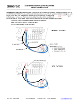
Connector
(rear
view)
Tektronix
Part
Number
131-077-00
The
temperature-sensing
transistor
is
connected to the
7D13
through the
front-panel
PROBE
connector
using
two-
conductor
shielded
cable
and a connector
plug
(Tektronix
Part
Number
131-0778-00)
.
A
wiring
diagram
Is
shown
in
Fig
.
2-2
.
Schematic
diagram
of
temperature-sensing
transistor
con-
Fig
.
2-2
.
~
netted
to
probe
connector
.

Introduction
l"his
section
of
the
manual
contains
a
description
of
the
circuitry
used
in
the
7D13
Digital
Multimeter
Plug-I
n
.
The
description
begins
with
a
discussion of
the the
instrument
using
the
Block
Diagram
given
in
the
Diagrams
section
.
Following
the
block
diagram
description
is
a
more
detailed
description,
particularly
for
circuits
unique
to
this
instru-
ment
.
If
more
information
is
desired
on
commonly
used
circuits,
refer
to
the
following
textbooks
:
Jacob
Millman and
Herbert
Taub,
"Pulse,
Digital,
and
Switching
Waveforms",
McGraw-Hill,
New
York,
1965
.
Digital
logic
techniques
are
used to
perform
many
func-
tions
within
this
instrument
.
'The
function
and
operation
of
the
logic circuits
are
described
using
logic
symbologyand
terminology
.
For
further
information,
see
Logic
Fundamen-
tals
in
Section
3
of
the
oscilloscope
instruction
manual
.
Following
the
detailed
circuit
description
is
a
brief
dis-
cussion
of
the
readout system
used
in
Tektronix
7000-series
Oscilloscopes
.
If
more
information
is
desired
on
the
readout
system,
refer
to
the
instruction
manual
for
the
oscilloscope
.
NOTE
Change
information,
if
any,
affecting
this
section
will
be
found
at
the
rear
of
this
manual
.
7®13
circuit
isolation
is
accomplished
by
transformer
coupling
of
signals
and
by the
Floating
Power
Supply
.
The
Attenuator
and
Switching
circuit selects
and
attenuates,
when
necessary, inputs to
be
measured from
the
INPUT
connectors,
PROBE
connector,
Ohms
Converter,
and
Temperature
Measurement
circuits
.
A
positive
or
nega-
tive
output
voltage
is
provided
to
the
~Gm~
Converter
which
is
within
the
limits
of
the
Floating
Power
Supply
.
Tektronix
Circuit
Concepts
Books
(order
from
your
local
Tektronix
Field
Office or
representative)
:
-
1 -
he
~Gm~
Converter
converts
the
positive
or
negative
input
voltage
to
a
single-polarity
current
output
for the
Digital
Concepts,
Tektronix
Part
No
.
062-1030-00
.
Analog-to-Pulse-Width
Converter
.
The
~G
m
~
Converter
also
provides
an
output
indicating
the
relative
polarity
of
the
Power
Supply
Circuits,
Tektronix
Part
No
.
062-0888-
input
voltage
to
the
Polarity
Indicator
circuit
.
01
.
When
the
MODE/RANGE
switch
is
set
to
RESIST-
ANCE,
the
Ohms
Converter measures
resistance
connected
between
the
INPUT
connectors
.
The
output
provided
to
the
~Gm~
Converter
is
a
voltage proportional
to
the
resist-
ance
being
measured
.
The
Analog-to-Pulse-Width
Converter
measures
the
single-polarity
current
from
the
~Gm~
Converter
.
The
Analog-to-Pulse-Width
Converter
is
clocked
by
the
Last
Count
pulse
from
the
Counter
to
provide
an
output
S
-
FORE
COMMAND
pulse
to
the
Memory
circuit
.
The
time
relation-
ship
between
this
output
pulse
and
the
Last
Count
is
a
direct
function
of
the
analog
input current
from
the
~G
m
~
Converter
.
The
Polarity
Indicator
circuit
provides
an output
to
the
Readout
Logic
to
indicate
the
relative
polarity
of
the
input
voltage
.
AlI
references
to
direction
of
current
in this
manual
are
in
terms
of
conventional
current,'
i
.e
.,
from
plus
to
minus
.
The
Clock
generates
an
80
kilohertz
clock
signal
.
The
80
kilohertz
signal
is
counted
down
by
the
-2
stage
to pro-
vide
a
40
kilohertz
signal
which
is
counted
by
the
Counter
circuit,
and
which
is
used
to
trigger
the
Floating
Power
BLOCK
DIAGRAM
DESCRIPTION
Supply
.
The
heavy
dashed
line
on
the
Block
Diagram
encloses
the
measurement
input
circuits
.
These
circuits
are
isolated
The
Counter
circuit
continually
counts the 40
kilohertz
from
the
remainder
of
the
7D13
circuits
to
allow
them
to
signal
from
the
Clock
.
The
Counter
output
to
the
Memory
follow
a
common-mode
voltage
up
to
1500
volts
.
-
The
input
circuit
is
in
a
1-2-4-8
binary-coded-decimal
(BCD)
form
.

Circuit
Description--7D13
Other
Counter
outputs
are
a
two
kilohertz
trigger
to
the
DC
Volts
.
When
the
MODE/RANGE
switch
is
set
to
any
Temperature
Measurement
circuit,
and
a
Last
Count
pulse
of the
DC
VOLTS
ranges,
it
connects
the
INPUT
connec-
to
the
Analog-to-Pulse-Width
Converterand
Readout
Logic
tors
(or
the
high
and low
terminals of the
PROBE
con-
circuits
.
-
The
Last
Count
indicates
that the
Counter
is
full
vector)
across
R60
.
R60
is
a
precision,
tapped,
10
megohm
(has
counted
to
8000)
.
resistor
which
is
used
as
an
input
resistor/voltage
divider
for
the
DCVOLTS
mode
.
Thus,
the
voltage
being
measured
is
applied across the
full
10
megohm
resistance
of
R60
while
The
Memory
circuit
reads the
1-2-4-8
BCD
output
from
the
V
x
output
is
taken
from
the
appropriate
tap
for
each
the
Counter
on
comm
and
of the
Analog-to-Pulse-Width
full-scale
DC
VOLTS
range
.
Converter
S`I""ORE
COMMAND
output
.
-
f~ime-slot
data
from
the
Readout
Logic
circuit
enables
the
Memory
to
provide
a
BCD
output
having the
proper
time
relationship
to
drive
DC
Current
.
When
the
MODE/RANGE
switch
is
set
to
a
the
Readout
Logic
.
DC
CURRENT
range,
one
or
more
sections
of
R10
or
R60
is
connected
as
a
shunt
across the
INPUT
connectors
.
The
voltage
drop
resulting
from
a
measured
DC
current
through
T'he
Readout
Logic
receives
the
BCD
input
from
the
the
selected
shunt
resistance
provides
the
V
x
output
to the
Memory
circuit
and
encodes
data
so the oscilloscope
read-
IGm~
Converter
.
out system
can
display a
digital
readout
of
the
measure-
ment
.
The
Temperature
Measurement
circuit
provides
an out-
put
voltage
which
varies
directly
with
the
temperature
of a
temperature-sensing
transistor
(connected
to
the
Tempera-
ture
Measurement
circuit
via
the front-panel
PROBE
connector)
.
The
output
voltage
can
be
selected
by
the
MODE/RANGE
switch
to
be
measured
and
displayed
as
a
temperature
readout
.
The
output
voltage
is
also
available
at
the
front-panel
TEMP
OUT
connectors
for
any
setting
of
the
MODE/RANGE
switch
.
INPUT
SWITCHING
AND
OHMS
CONVERTER
The
constant-current
source
consisting
of
039
and
U45
supplies
a
constant current
through
R36
to
the
output
of
Input
Switching
U32
at
pin
6
.
VR47
sets
the voltage
at
the
plus input of
General
.
The
Input
Switching
circuit
consists
of the
U45
.
The
output
of
U45
at
pin
6
is
fed
back
to the
minus
input
sections
of
the
MODE/RANGE
switch,
attenuator
input
through
the gate-source
junction
of
039
to
obtain
a
null
voltage
.
Thus,
the voltage
at
the
junction
of
the
source
resistors,
and
input-protection
components
.
(Other
sections
of
039
and
R40
will
be
the
same
as
the
voltage
set
by
of
the
MODE/RANGE
switch
encode
the
readout
logic
which
is
described
under
Readout
Logic
.)
VR47
.
Since
the
voltage
across
R40, R42,
and
R44
is
held
constant
by
U45-039,
the
current
through
them
is
adjust-
able
by
R44,
Ohms
Adjustment
.
The
Input
Switching
circuit selects
and
attenuates,
when
necessary,
a
measurement
input
to
provide
an output
volt
age
to
the
~G,r,~
Converter
circuit
.
The
output
voltage,
V
x
,
024
effectively
inverts
the
inputs
to
U32
.
Thus
pin
appears
across
the points
labeled
V
x
and
DVM
Low
.
The
3-024
becomes
the
plus
input to the operational amplifier
output
voltage
should not exceed
the
maximum
input
volt-
and
pin
7-024
becomes
the
minus
input
.
In
the
RESIS
-
r
.,
-
age
limits
of
the
~Gm~
Converter
(limited
by
the Floating
ANCE
ranges,
R60
provides
feedback
from
the
output
of
Power
Supply
to plus or
minus
15
volts)
.
Thus,
attenuation
U32
to
the plus
input
(pin
3-024)
.
The
operation
of
U32-
of
the
measurement
input
is
necessary
when
it
would
other-
024
is
such
that
it
produces
a
null
voltage
at
the
plus
input
wise
exceed
these
limits
.
(pin
3-07_4)
which
is
equal
to
the voltage
established
at
the
minus
input
(pin
7-024)
.
The
constant current
through
R36
from
U45-039
establishes
a
fixed
voltage
between
the
output
of
U32
and
the
minus
input
(pin
7-024)
in
all
The
Temperature
Measurement
circuit
and
the
Ohms
RESISTANCE
ranges
.
Therefore,
the voltage
drop
required
Converter
have
outputs
which
are
within
the
maximum
across
R60
to
produce
a
null
is
also
fixed
.
input voltage
limits
of the ~G
m
~
Converter
.
Thus,
when
either
of these
outputs
is
selected
by
the
MODE/RANGE
switch,
it is
connected
directly
to
the
~G,n~
Converter
with-
As
the
MODE/RANGES
switch
is
set
to the various
out
attenuation
.
RESISTANCE
RANGES,
different
sections
of
R60
are
3-
2
Fuse
F6,
in series
with
the
shunt
resistance,
protects
R10
and
R60
from
damagedue
to
excessive
input current
.
Rectifier
diodes
CR7-CR8
protect
R10
and
R60
from
damage
due
to excessive
input
voltage
.
Ohms
Converter
.
This
circuit
is
madeup
of
constant-
current
source
039
and
U45,
operational
amplifier
U32,
high-impedance
input
024,
and
constant-current
source
028
.
A
simplified
diagram
of
the
Ohms
Converter
circuit
is
shown
in
F
ig
.
3-1
.

Circuit
Description-7D13
Fig,
3-1
.
Simplified
diagram
of
the
Ohms
Converter
circuit
.
Constant-
Current
Source
U45,
039
DVM
Low
connected
into
the
circuit
.
Since
the
voltage
drop
necessary
Delay
stage
of the
Memory
circuit
(diagram
3)
.
Also, an
across
R60
to
establish
a
null at
the
plus
input
(pin
3-024)
output
signal,
MINUS,
is
provided
to the
Readout
Logic
to
is
constant
for
all
RESISTANCE
ranges,
the
current
indicate
that
V
X
is
negative
with
respect
to
DVM
Low
;
through
R60
must change
as
the
resistance
of
R60
is
effec-
therefore,
a
minus
(--)
symbol
should
be
displayed
.
tively
increased or
decreased
.
However,
once
the
RESIST-
ANCE
range
is
selected,
the
current
through
the
selected
sections)
of
R60
is
held
constant
by
U32-024
.
This
The
~G
m
~
Converter and
Analog-to-Pulse-Width
Con-
constant
current
is
available
at the
HIGH
INPUT`
connector
verter
circuits,
along
with
the
Ohms
Converter,
are
powered
through
R12
and
F12
to
produce
a
voltage
drop
across
an
from
the Floating
Power
Supply
to
allow
them
to
follow
a
unknown
resistance
connected
between
the
INPU1~
connec-
common-mode
voltage
up
to
1500
volts
.
Signals
between
tors
.
The
resultant
voltage
drop
across
the
unknown
resist-
the
floating
circuits
and
other
circuits
in
the
7D13
are
ance
produces
an
output
at
the
V
x
connector
which
is
transformer-coupled
for
DC
isolation
.
measured
by
the
voltmeter
circuits
and
read
out
as
a
resist-
ance
value
.
~G,nI
CONVERTER
AND
ANALOG-TO-PULSE-WIDTH
CONVERTER
The
~G,
i
- i ~
Converter
consists
of
0103,0105,0108,
General
0125,
0135,
0141,0118,
and
U
128
.
- T
-
his
circuit
provides
a
single-polarity
current
output
to
be
integrated
by
the
The
~G
m
~
Converter
and
Analog-to-Pulse-Width
Convert-
Integrator
stage
.
The
level
of
this
current
is
determined
by
er
circuits
measure
input
voltage
V
X
with
respect to
DVM
the
absolute
value of
V
x
with
respect
to
DVM
Low
.
Also,
Low
from
t
he
Inp
ut
Switching
circuit
and
generate
an out-
an
output
to
0173
in
the
Polarity
Indicator
circuit
indi-
put
signal,
STORE
COMMAND,
to
the
Store
Command
Gates
the
polarity
of
V
X
with
respect
to
DVM
Low
.
IG,~-,~
Converter
3-3

Circuit
Description-7D13
The
output
signal
is
a
current
into
the
~G,-n~
Converter
determined by the
amount
of
current
demanded
by
the
from
the
Integrator
current-summing
point
(at
the
gate of
~Gm~
Converter
.
l~he
slope
of
the
negative
portion
of
the
Q152)
.
U
118
or
U
128
"sink"
the
signal
through
CR
142
as
ramp
is
determined
by
the
difference
between
the
reference
determined
by
the
polarity
of
V
x
.
Field-effect
diode
current
and
the
current
into
the
~Gm~
Converter
.
CR
142
limits
the
maximum
signal
current
amplitude
.
Fig
.
3-2
shows
the
time
relationship
of
the
Counter
out-
Q103
provides
a
high-impedance
input
to
U118
for
V
x
,
put and
the
Analog-to-Pulse-Width
Converter
circuits
.
The
Because
Q103
inverts
the
inputs to
U118,
pin
3
(gate)
Integrator
ramp
waveform
represents
the
Integrator
output
becomes
the
plus
input
to
U118
and
pin
7
becomes
the
for
a
full-scale
measurement
(e .g
.,
2
.000
V)
.
Regardless
of
minus
input
.
Constant-current
sources
Q105-Q113,
in
con-
the
measurement
input,
the
duration
of
the
ramp
remains
junction
with
bootstrap
emitter-follower
Q108,
maintain
the
same
;
the
positive
portion
of the
ramp
always
ends
at
the
parameters
of
Q103
constant
over
a
wide
range
of
T0,
corresponding
to
the
Last
Count
from
the
Counter
.
operating
conditions
.
CR101-CR102
limit
the
maximum
value
of
V
x by
conducting
if
V
x
to
DVM
Low
exceeds
about
plus
or
minus
15
volts
(referenced
to
floating
Zero-Crossing
Comparator
.
The
Zero-Crossing
Compara-
ground)
.
R115,
Zero
Adjustment,
provides
an
adjustment
tor,
U158,
generates
a
negative-going
pulse
when
the
to
balance
the quiescent
current
through the
two
halves
of
negative-going
ramp
at
its
input reaches
the
zero-volt
level
Q103
.
(referenced
to
floating
ground)
.
The
relationship
between
The
voltage
level at
the
output
of
U118
(pin
6)
follows
the
voltage
level
at
the
plus
input
(pin
3-Q103)
.
The
output
is
fed
back
to
the
minus
input
(pin
7-Q103)
to obtain
a
null
;
the
feedback
path
is
determined
by
the
polarity
of
V
x
.
The
voltage
level at
the output
of
U128
(pin
6)
follows
the
level at
the
gate of
Q125when
V
x
is
negative
with
respect
to
DVM
Low
.
For
zero or
positive
levels
of
V
x
,
however,
the output
of
U
118
is
negative
.
The
operational
amplifier
(U
118
or
U
128)
with
the
negative
voltage
level
output
becomes
the
output
signal
current
sink
.
Assuming
a
negative
value
of
V
x with
respect
to
DVM
Low,
pin
6-U118
will
be
negative to
forward
bias
CR
119
.
CR
119
becomes
the
feedback
path
between
the
output and
the
minus
input
of
U118
.
VR139
keeps
the
gate
of
Q141
more
negative
than
the
source,
to
pinch
off
cur-
rent
through
Q141
.
The
signal
current,
therefore,
flows
through
Q135
(drain
to
source),
R
124,
R
122,
and
CR
119
topin6ofU118
.
~T
-
he
circuit
operation
for
positive
levels
of
V
x
is
similar
to
that
for
negative
levels
.
In this
case,
Q135
is
pinched
off
and
the
signal
current
path
is
through
Q141, R122,R124,
and
CR
130
to
pin
6
of
U
128
.
Analog-to-Pulse-Width
Converter
3-4
T2
=
FULL
SCALE
OF
COUNTER
RESETS
TO
HERO
AFTER
-
r2
COUNTER
OUTPUT
X10
3
INTEGRATOR
RAMP
(OUTPUT)
0-VOLT
LEVEL
-
INPUTS
OU`rPUTS
z
O
U
F
N
Q
J
0
1
2
3
4
5
6
7
0
1
2
L_L_L_-_l__
.L
.
._l_
._l-_1-
.- 1
._--1__
._
.L__
TZ TO
T1
Integrator
.
The
Integrator
circuit,
madeup
of
Q152
and
U155,
generates
a
ramp
output
.
~l
-
he
ramp
amplitude
and
slope
are functions
of
the
current
into
or
out
of
the
current-
summing
point
at
the
gate
of
Q152
.
The
positive-going
por-
tion
of
the
ramp
charges
with
the
current
going
to
the
~G
m
~
Converter
.
The
ramp
will
go
positive
until
reset
by
the
reference current being
switched
into
the
current-summing
F
;y
.3-2
.Analog-to-Pulse-Width
Converter
circuitwaveformsshowing
point
.
The
voltage
level
reached
by
the
positive
ramp
is
their
relationship
to
the
Counter
output
.
STORE
COMMAND
0187
Collector

the
ramp
and
the
output
of
the
Zero-crossing
Comparator
is
The
output
of
U
118-pin
6
in
the
~G,-
r
,~
Converter
follows
shown
in
Fig
.
3-2
;
the
input
to
U159B
at
pin
4
is
the
V
x
(see
~Gm~
Converter)
.
When
V
x
is
positive,
the
base of
output
of
the
Zero-Crossing
Comparator
.
0173
is
positive
.
This
results
in
0173
being
saturated
.
Thus,
the
collector
of
0173
is
at
its
LO
level
to
inhibit
U
159A
.
Zero-Crossing
Flip-Flop
.
The
Zero-Crossing
Flip-Flop
is
an
RS
flip-flop
made
up
of
U159B
and
D
.
This
circuit
has
two
inputs
and
two
complementary
outputs,
all
of
which
When
V
x
is
negative
with
respect
to
DVM
Low,
0173
is
are
shown
in
Fig
.
3-2
.
reverse
biased
by
the
LO
level
at
its
base
.
The
resulting
HI
level at
the
collector
of
0173
enables
U159A
.
U159A
will
have
an
output
each time
the
input
from
pin
11-U159D
One
input
to
the
flip-flop
at
pin
12-U159D
is
a
negative-
goes
HI
.
l~he
output
of
U159A
is
connected
to
U189A
going
pulse
derived
from
the
LAST
-
COUNT
from
the
through
U159C,
T179,
and
0182
to
set
the
output
of
Counter
through
T168
and
0169
.
The
other input
at
pin
U189A,
MINUS,
to
a
LO
level
.
4-U
159B
is
the
negative-going
pulse
from
the
Zero-Crossing
Comparator
.
The
output
pulses
from
the
flip-flop
are
initiated
by
the
Last
Count
input
and
terminated
by
the
Zero-Crossing
input
.
CLOCK,
COUNTER,
AND
MEMORY
Reference
Current
Source
.
The
Reference
Current
Source,
consisting
of
U145, 0149,
and
0163
supplies
a
constant
current
called
the
reference
current,
I
r
.
VR144
and
U145
establish
a
constant
voltage
at
the source
of
0149
.
R148,
Gain
Adjustment,
then
provides
adjustment
of
I
r
through
R
148,
R
149,
and
0149
.
I
r
is
sinked
from the
drain
of
0149
to
the
Floating
Power
Supply
common
through
CR165,
VR164,
and
0163
when
pin
6-U159B
is
HI
.
When
the
Last
Count
pulse
sets
pin
6-U159B
to
LO,
0163
is
turned off
to
reverse
bias
CR165
. I
r
is
now
switched
through
CR150
to
the
Integra-
tor
current-summing
point
to
end
the
positive
portion
of
the
ramp
(see
Fig
.
3-2)
.
Clock
The
Clock
consists
of
a
collector-coupled
astable
multi-
The
output
from
pin
6-U159B
(negative-going
pulse)
is
vibrator,
0200
and
0206,
and
a
divide
by
two
counter,
connected
to
the
Reference
Current Source
to
switch the
U208B
.
reference current
into
the
Integrator
current-summing
point
.
The
output from
pin
11-U159D
(positive-going
pulse)
is
connected
to
the
Polarity
Indicator
circuit
and
to
The
multivibrator
generates
an
80
kilohertz
clock
signal
.
0187
via
C184
and
T185
.
The
80
kilohertz
signal
is
divided
by
two
by
U208B
to
provide
a
40
kilohertz
clock
signal
.
The
40
kilohertz
signal
is
connected
to
the
Counter
circuit,
the
Store
Command
The
resulting
signal at
the
collector
of
0187
is
a
negative
Delay
stage
of
the
Memory
circuit
and
the
Floating
Power
pulse,
STORE
COMMAND,
coincident
with
the
Zero-
Supply
.
R203,
Clock,
provides
adjustment
of
the
80
Crossing
input
to
U159D
(see
Fig
.
3-2)
. -
f~his
signal
is
con-
kilohertz
frequency
.
nected
to
the
Store
Command
Delay
circuit
and
to
the
Polarity
Indicator
circuit
.
Counter
The
Counter
circuit
consists
of
divide
by 10
counters,
0210,
U212,
and
U214,
and
a
divide
by
eight
counter,
U208A
.
The
Counter
counts
the
40
kilohertz
clock
signal
to
provide
binary-coded-decimal
outputs
to
the
Memory
.
The
2
kilohertz
pulse
from
U212
is
connected
to
the
Temperature
Measurement
circuit
for
switching
.
Also,
the
positive
LAST
COUN7
output
from
U208A
is
connected
to
the
Analog-to-Pulse-Width
Converter
to
indicate
a
full
count
;
and
to
the
Readout
Logic
to
clock
the
Over-Range
I
nd
icator
.
Memory
Circuit
Description--~7D13
The
Memory
circuit
includes
the
Storage
Registers,
Store
Command
Delay,
and
the Multiplexers
.
Polarity
Indicator
.
The
Polarity
Indicator
circuit
consisting
of
0173,
U
159A,
U
159C,
0182,
and
U
189A
provides
the
MINUS
signal to
the
Readout
Logic
circuit
.
Storage
Registers
. -
rhe
Storage
Registers consist
of
MINUS,
when
at
the
LO
level,
indicates
that
the
polarity
U218,
U220, U222,
and
U224
.
The
Storage
Registers
symbol
in
the readout
display
should
be a
minus
(--)
transfer
the
binary-coded-decimal
Counter
output
to
the
symbol
.
MINUS
is
at
the
LO
level
when
the
relative
polarity
Multiplexers
when
strobed
by
the
STORE
COMMAND
of
V
x
is
negative
with
respect
to
DVM
Low
.
signal
from
the
Store
Command
Delay
stage
.
Thus, only
the

Circuit
Description--F7D13
Counter
output
up
to
the
time
of
the
STORE
COMMAND
signal
is
transferred
to
the
Multiplexers
and
Readout
Logic,
while
the
count
made
after
the
S~("ORE
COMMAND
is
not
passed
on
.
The
Storage
Register
outputs
to
the
Multiplexers
are
inverted
in
order
to
drive
the
Digital-to-Analog
Converter
in
the
Readout
Logic,
a
negative-input
device
.
would
be
displayed
.
TS-8
Multiplexer
.
The
Multiplexer
circuit
consists
of
U260
and
U262
.
The
Multiplexers
read
the
1-2-4-8
outputs
from
TS-9
the
Storage
Registers,
translating
only four
specific
bits at
any one
time
.
The
time
for
each
character
is
determined
by
----------
the
time-slot
data
from
the
Readout
Logic
circuit
driving
TS-10
the
Multiplexer
address
inputs
.
~I"he
Multiplexer
output
to
-°°-~~
the
Digital-to-Analog
Converter
in
the
Readout
Logic
is
a
time-slot
related
1-2-4-8
binary
code
.
General
3-6
READOUT
LOGIC
Encoding
Format
l°he
Store
Command
Delay
stage receives
the
STORE
---
_
._
._-
._
COMMAND
signal
from
the
Analog-to-Pulse-Width
Con-
TS-4
verter
and
provides
the
STORE
COMMAND
to
the
Storage
Registers
.
1
-
he
Sl`ORE
COM
MAN
D
signal
is
slightly
delayed
~°'°~w_
.___w__
by
this
stage
if
the
Sl
°
ORE~COMMAND
input
occurs
at
the
TS-5,
TS-6
same
time
that
the
40
kilohertz
Clock
signal
is
triggering
TS-7
the
Counter
.
Otherwise,
an
erratic
or
erroneous
count
-------__
._
.-
The
7D13
Readout
Logic
circuit
encodes
the
Row
and
Column
output
lines
(pins
B37
and
A37
respectively
of
the
Interface
Connector)
according
to
the
format
given
in
Table
3-1
.
The
time-slot
pulses
from
the
oscilloscope
readout
system
are
provided
to
the
Readout
Logic
circuit
through
the
Interface
Connector
.
Several
of
the
time-slot
pulses
are
also
connected
to
the
Memory
circuit
to
address
the
Multi-
plexers
.
l°he
1000
output
from
pin
9-U224,
is
provided
to
the
Readout
Logic
to
indicate
a
measurement
of
1000
or
more
.
TABLE
3-1
1000
is
LO
for
counts
of
1000
or
more
.
-
1`he
2000
output
7D13
READOUT
FORMAT
from
pin
6-U224
is
provided
to
the
Readout
Logic
to
indi-
_
.~_
._
.___
.____
._
.
__
.-___
.__
._
._
._____~
. .
.__
Gate
a
count
of
2000
or
more
.
2000
is
LO
only
for
counts
TIME-SLOT
~`
of
2000
and
greater,
which
enables
the
Over-Range
Indi-
NUMBER
DESC
RIPTI
ON
cator
circuit
.
~~_
.
,_
.____~__
.
_
:_
~--~,
.__
.~______
_
."
.
._
.
.
.a
.__
.
.
. .
.
. . . . .
. .
TS-1
_
y
Determines
decimal
position
.
Also,
encodes
a
JUMP
instruction
to
indicate
Store
Command
Delay
.
'The
Store
Command
Delay
over-ranging
.
stage
consists
of
0190,
U
189B,
U
195A,
U
195B,
U
195C,
-------
U195D,
and
Q216
.
TS-2
~
Not
used
TS-3
measurement
units
.
Not
used
Digital-to-Analog
Converter
Indicates
polarity
of
measurement
.
Most
significant
digit
of
measurement
readout
.
Remaining
three
digits
of
measurement
Encodes
m
(milli-)
and
k
(kilo-)
prefixes,
V
(volts)
and
C
(Celsius)
measurement
units
.
Encodes
A
(amperes)
and
SZ
(ohms)
The
Digital-to-Analog
Converter
circuit
includes
D-A
Converter,
U264,
and
time-slot
driver,
0259
.
The
Readout
Logic
circuit
encodes
the
Indicator
Oscillo-
scope
readout system
to
display
the
measurement
made
by
'I
-
ime-slot
pulses
TS-4, TS-5,
1°S-6,
and
TS-7
from
the
the
7D13
.
The
Readout
Logic
circuit
also
encodes
the
read-
Interface
Connector
are
connected
to
the
base
of
0259
via
out
system
to
display
the
appropriate
measurement
units
diodes
.
0259
then
drives
the
ENABLE
input
of
U264
at
and
polarity
symbols,
along
with
positioning
the
display
pin
8
.
decimal
point
and
indicating
an
over-range
measurement
.
The
INPU~Ts
to
0264
at
pins
2,
3,
4,
and 5
receive
the
A
discussion
entitled
Introduction
to
the
Readout
1-2-4-8
binary
code from the
Multiplexers
.
U264
then
System
following the
7D13
Circuit
Description
gives
a
brief
encodes
the
Column
Current
output
at
pin
15
according
to
description
of
the
readout system
used
in
Tektronix
the
binary
weight
of
each
number
;
the
position
of
each
7000-series
Oscilloscopes
.
figure
is
determined by
the
time-slot
pulses
(see
1~'able
3-1
) .

Over-Range
Indicator
The
Over-Range
Indicator, consisting
of
0232
and
Circuit
operation
.
The
temperature-sensing
transistor
is
0228,
causes
the
readout
display
(for
the
7D13
only)
to
connected
in
the
feedback
loop
(via
the
PROBE
connector)
blink
when
the
measurement
range
in
use
is
exceeded,
of
operational
amplifier
U319
with
the
collector
at
the
minus
input,
and
the
emitter
connected
to
the
output
through
R320
.
The
base
is
grounded
.
The
2000
input
to
the
base of
0228
from
the
Storage
Registers
is
HI
when
the
most
significant
digit
is
1
or
0
.
This
HI
level
saturates
0228
to sink
the
current
through
R234
when
it is
interrogated
by
time-slot
pulse
TS-1
.
T
-
he
base
of
0228
goes
LO
when
the
most
significant
digit
is
2
to
reverse-bias
0228
.
Now,
whenR234
is
interrogated
by
1 -
S-1,
a
JUMP
instruction
is
added
to
the
Row
Current
output
.
For a
given
current
input,
the
output
of
U319
forward
biases
the
emitter-base
junction
of
the
temperature-sensing
'The
input
to
0232
base
is
the
LAST
COUN~f
pulse
from
transistor
to
the
level
necessary
to
maintain
the
input
the
counter
which
goes
HI
at
the
last
count
(approximately
collector
current
.
Input
current
to
the
operational
amplifier
five
hertz
repetition
rate)
.
Each
time
the
LAST
COUNT
is
negligible,
and
thus
the
input
current
essentially
is
the
goes
HI,
0232
is
saturated
to sink
the
JUMP
instruction
collector
current
of
the temperature-sensing
transistor
.
current
to
ground
.
This
causes
the
display
to
blink
at
the
repetition
rate
of
the
LAST
COUNT
.
The
output
of
U319
at
pin
6
is
a
two
kilohertz
square
wave
(and
a
DC
component)
with
an
amplitude
determined
Zero-Cancel
.
Zero
cancelling
is
encoded
when
the
most
by
the
temperature
of
the
temperature-sensing
transistor
.
significant
digit
is
0, so
that
the
0
does not
appear
in
the
This
signal
is
AC-coupled
through
C329
to
the
drains
of
readout
display
.
This
is
accomplished
during
time-slot
four,
0326
and
0330
.
since
this
is
the
position
held
by
the
most
significant digit
.
0326
and
0330
demodulate
the
signal
from
the
output
°C`he
base of
02
.38
is
conne
cted
to
pin
9-U224
in
the
of
0319
.
0326-0330
are
driven
from
opposite
halves
of
Storage
Register
circuit
.
The
1000
input
to
0238
is
LO
multivibrator
0301-0305,
to
be
turned
on
during
opposite
when
the
most
significant
digit
is
0,
and HI
for
any
other
half
cycles
.
When0326
turns
on,
it
restores
the
negative
value
.
A
HI
level
on the
base
of
0238
saturates
it
to
sink
extremity
of
the square
wave
signal
to
ground
.
When0326
the
T
-
S-4
current
through
R239
to
ground
.
A
LO
level at
is
off
and
0330
on,
the
positive
extremity
is
passed
through
the
base
of
0238
allows
the
TS-4
current
through
R239
to
0330
to
C332
.
C332
acts
as
a
low-pass
filter
.
-
The
voltage
pass
to
the
Row
Current
output
through
CR239
.
This
developed
across
C332
is
the
demodulated
output
of
U319,
current
forces
a
skip
in
time-slot
four,
thus
cancelling
the
and
its
level
follows
the
average
amplitude
of
the square
initial
0
.
waves
.
MODE/RANGE
Switch
TEMPERATURE
MEASUREMENT
AND
°Che
MODE/RANGE
switch
encodes
the
readout
system
FLOATING
POWER
SUPPLY
by
switching
resistors
between
the
appropriate
time-slot
Temperature
Measurement
inputs
and
the
Column
and/or
Row
Current
output
lines
.
The
readout system
then
displays
the
measurement
unit
General
.
The
Temperature
Measurement
circuit
consists
and
prefix
for the
measurement
mode
selected,
and
the
of an
emitter
coupled
multivibrator
triggered
by
the
two
decimal
point
is
positioned
properly
for the
measurement
kilohertz
signal
from
the
Counter
circuit
0301-0305,
cur-
rangeselected
.
rent
level
switch
0315,
demodulator
FE
-
fs
0326-0330,
operational
amplifier
U319,
and
operational
amplifier
U
335
.
Also,
a
positive
polarity
symbol
(+)
is
encoded
by
the
MODE/RANGE
switch
when
set
for
DC VOLTS,DC
CURREN
. .
f
.
',
and
TEMPERATURE
measurements
.
If
the
Theory
of
operation
.
Under
the
conditions
of zero
MINUS
input
to
the
base of
0278
goes
to
a
LO
level,
collector-base
voltage
and
sufficient
emitter-base
voltage,
current
is
added
to
the
Column
Current
output through
the
collector
current
of
a
transistor
can be
expressed
as
an
R277
and
CR278
during
1
-
S-3
.
-
This
added
current
in
TS-3
exponential
function
of
the
emitter-base
voltage
and
the
results
in
the
.
symbol
being
changed
to
-
.
junction
temperature
.
By
switching the
collector
current
between
two
levels,
the
resulting
difference
in
emitter-base
voltage
is
a
linear
function
of
temperature
.
Circuit
Description---7D13
The
collector
current
of
the temperature-sensing
transis-
tor
is
switched
between
two
levels
by
0315
.
The
current
is
limited
by
R317
when0315
is
off,
to
about
one-tenth
the
current
through
both
R317
and
R315-0315
when
0315
is
on
.
3-7

Circuit
Description-7D13
The
voltage
developed
across
C332
is
connected
to
the
age for
each
supply
is
determined by a
temperature-
plus
input
of
the
output
operational
amplifier,
U335
.
The
compensating
zener
reference
diode
which
sets
the
base
output
of
U335
at
pin
6
is
fed
back
to
the
minus
input
voltage
of
the
series
regulator
transistor
.
through
R337
and
R339
.
R337,
(temperature)
Gain,
pro-
vides
adjustment
of
the
feedback
to
the
minus
input
so that
INTR®pUC"I
-
ION
"C'O
~"HE
READOUT`
SYSTEM
the output
of
U335
can be
calibrated
to
be 10
millivolts
per
degree
Celsius
.
R346,
Offset,
adjusts
the
bias
on
U335
for
IntroduCtlon
an output
of
0
volts
when
the
temperature
of
the
temperature-sensing
transistor
is
zero
degrees
Celsius
.
The
following
discussion
is
provided
to
acquaint
the
7D13
user
with
the
Readout
System
used
in
Tektronix
7000-series
Oscilloscopes
.
Since
the
oscilloscope
Readout
The
voltage
output
of
U335
is
connected
directly
to
the
System
provides
the
digital
readout
for
the
7D13,
it is
front-panel
TEMP
OUT
connectors
to
provide
an
analog
necessary
to
relate
the
function
of
the
7D13
to
the
Read-
temperature
signal
.
This
voltage
output
is
also
connected
to
out
System
to
gain
a
better
understanding
of
the
7D13
the
input
of
the
~Gm~
Converter
when
the
MODE/RANGE
operation
.
A
detailed
circuit
description
of
the
7000-series
switch
is
set
to
TEMPERATURE
.
This
voltage
is
measured
Readout
System
is
given
in
the
oscilloscope instruction
by
the
voltmeter
circuits
and
read
out
as
a
temperature
manual
.
measurement
.
FIOating
Power
Supply
The
Readout
System
in
the
7000-series
oscilloscopes
provides
alpha-numeric
display
of
information
encoded
by
The
Floating
Power
Supply
is
a
DC-to-DC
Converter
the
plug-in
units
.
This
display
is
presented
on
the
CRT,
and
supplying
outputs
of
+15
volts,
---15
volts,
and
+5
volts
is
written
by
the
CRT
beam
on
a
time-shared
basis
with
the
from
the-~-15-volt
supply
in
the
Indicator
Oscilloscope
.
analog
waveform
display
.
The
Floating
Power
Supply
consists
of
inverter
0408-0415
.
Emitter-follower
0401
drives
0408
through
R404
from
the
40
kilohertz
Clock
pulse
.
The
center-tapped
primary
winding of
transformer
T420
is
the
collector
load
for
0408
and
0415
.
Since
only
0408
or
0415
is
conducting
at
any
one
time,
the
inverter
is
chopping
at
a
20
kilohertz
rate,
or one-half
the
input
fre-
quency
.
Data
is
encoded
on
these
output
lines
either
by
con-
necting
resistors
between
them
and
the
time-slot
input
lines
The
secondary
windings
of
1"420
provide
a
square-wave
or
by
generating
equivalent
currents
.
The
resultant
output
output
to
bridge
rectifiers
CR422
and
CR440
.
Each
bridge
is
a
sequence
of
analog
current
levels
on
the
row
and
consists
of
four
separate
diodes
.
Each
output of
the
column
output
lines
.
The
row
and
column
current
levels
are
Floating
Power
Supply
is
regulated
by a
series
regulator
decoded
by
the
Readout
System
to
address
a
character
transistor
;
0433,
0438,
and
0447
for the
+15-volt,
matrix
during
each
time-slot,
thus
selecting
a
character
to
--15-volt,
and
+5-volt
outputs
respectively
.
The
output
volt-
be
displayed
or
a
special
instruction
to
be
followed
.
The
Readout
System
The
Readout
System
produces
a
pulse
train
consisting
of
10
negative-going
pulses
called
time-slots
.
1-
hese
pulses
are
assigned
time-slot
numbers
corresponding
to
their
relative
position
in
the
pulse
train
.
Each
time-slot
pulse
is
directed
to
one
of
ten
output
lines,
labeled
TS-1
through
TS-10
(time-slots
one
through
ten)
and
are
connected
to
the
verti-
cal
and
horizontal
plug-in
compartments
.
Two
output
lines,
row and
column,
are
connected from
each
channel
(two
channels
per
plug-in
compartment)
back
to
the
Readout
System
.

Change
information,
if
any,
affecting
this
section
will
be
found
at
the rear
of
this
manual
.
I
ntroduction
Lu
brication
This
section
of
the
manual
contains
maintenance
infor-
Use
a
cleaning-type
lubricant
on
shaft
bushings,
inter-
mation
for
use
in
preventive
maintenance,
corrective
connecting
plug
contacts,
and
switch
contacts
.
Lubricate
maintenance,
and
troubleshooting
of the
7D13
.
switch
detents
with
a
heavier
grease
.
A
lubrication
kit
containing
the
necessary
lubricating
materials
and
instruc-
tions
is
available
through
any
Tektronix
Field
Office
.
Order
Further
maintenance
information
relating
to
component
Tektronix
Part
Number
003-0342-00
.
color
codes
and
soldering
techniques
can
be
found
in
the
instruction
manuals
for
the
7000-series
oscilloscopes
.
General
Preventive
maintenance,
consisting
of
cleaning,
visual
inspection,
lubrication,
etc
.,
performed
on
a
regular
basis,
will
improve
the
reliability
of
this
instrument
.
Periodic
checks
on
the
semiconductor
devices
used
in
the
unit
are
not
recommended
as a preventive
maintenance
measure
.
See
semiconductor-checking
information
given
under
Troubleshooting
.
The
following
is
provided
to
augment
information
Cleaning
contained
in
other
sections
of
this
manual
when
trouble-
shooting
the
7D13
.
.1"he
schematic diagrams,
Circuit
Description,
and
Calibration
sections
should
be
used
to
full
advantage
.
"fhe
Circuit
Description
section
gives
detailed
information
on
circuit
behavior
and
output
requirements
.
Avoid
the use
of chemical
cleaning
agents
which
might
damage
the
plastics
in this
instrument
.
Avoid
Troubleshooting
Aids
chemicals
containing
benzene,
toluene,
xylene,
acetone,
or
similar
solvents
.
Diagrams
.
Circuit
diagrams
are given
on
foldout
pages
in
Section
7
.
The
circuit
number
and
electrical
value of
each
component
in
this
instrument
are
shownon
the
diagrams
.
Front
Panel
.
Loose
dust
may
be
removed
with
a
soft
Important
voltages
are
also
shown
.
cloth
or
a
dry
paint
brush
.
Water
and
mild
detergent
may
be
used
;
however,
abrasive
cleaners
should
not
be
used
.
Circuit
Board
.
~fhe
circuit
board
used
in
the
7D13
is
outlined
on
the
schematic
diagrams,
and
a
photograph
of
Interior
.
Cleaning
the
interior
of the
unit
should
pre-
the
board
is
shownon
the
back
of
the
Block
Diagram
.
Each
cede
calibration,
since
the
cleaning
process
could
alter
the
board-mounted
electrical
component
is
identified
on
the
settings
of the
calibration
adjustments
.
Use
low-velocity
photograph
by
its
circuit
number
.
compressed
air
to
blow
off
the
accumulated
dust
.
Hardened
dirt
can
be
removed
with
a
soft,
dry
paint brush,
cotton-
tipped
swab,
or cloth
dampened
with
a
mild
detergent
and
Component
and
Wiring
Color
Code
.
Colored
stripes
or
water
solution
.
dots
on
resistors
and
capacitors
signify
electrical
values,
PREVENTIVE
MAINTENANCE
Recalibration
General
`TROUBLESHOOTING
7D13
`To
ensure
accurate
measurements,
the
7D13
should
be
checked
after
each
1000
hours
of
operation
or
every
six
months
if
used
infrequently
.
A
complete
performance
check
procedure
is
given
in
Part
I
of
Section
5
.
The
performance
check
procedure
can
be
helpful
in
isolating
major
troubles
in
the unit
.
Moreover,
minor
troubles
not
apparent
during
regular
operation
may
be
revealed
and
corrected
.

Maintenance--~7D73
tolerances,
etc
.,
according
to
the
EIA
standard
color
code
.
3
.
Visual
Check
.
Visually
check
the
portion
of the
Components
not
color
coded
usually
have
the
value
printed
instrument
in
which
the
trouble
is
suspected
.
Many
troubles
on
the
body
.
can
be
located
by
visual
indications,
such
as
unsoldered
connections,
broken
wires,
damaged
circuit
boards,
damaged
components,
etc
.
The
insulated
wires
used
for
interconnection
in
the
7D13
are
color
coded
to facilitate
tracing
a
wire
from
one
point to
another
in
the
unit
.
4
.
Check
Instrument
Performance
.
Check
the
calibra-
tion
of the
unit,
or the
affected
circuit
by
performing
Part
I
-
Performance
Check
Procedure
of
Section
5
.
The
apparent
Semiconductor
Lead
Configuration
.
Fig
.
4-1
shows
the
trouble
may
only
be
a
result
of
misadjustment
and
may
be
lead
configuration
of
the
semiconductor
devices
used
in
this
corrected
by
calibration
.
Complete
calibration
instructions
instrument
.
are
given
in
Part
I
I
of
Section
5
.
~`roubleshooting
Equipment
5
.
Check
Voltages
and
Waveforms
.
Often
the
defective
The
following
equipment
is
useful
for
troubleshooting
component
or
stage
can
be
located
by
checking
for
the
the
7D13
:
correct
voltage or
waveform
in
the
circuit
.
Typical
voltages
and
Waveforms
are
given
on
the
diagrams
;
however,
these
1
.
Semiconductor
Tester--Some
means
of
testing
the
are
not
absolute
and
may
vary
slightly
between
instru-
transistors,
diodes,
and
FET's
used
in this
instrument
is
means
.
To
obtain
operating
conditions
similar
to
those
used
helpful
.
A
transistor-curve tracer
such
as
the
Tektronix
to
take
these
readings,
see
the
instructions
in
the
Diagrams
Type576
will
give
the
most
complete
information
.
section
.
2
.
DC
Voltmeter
and
Ohmmeter-A
voltmeter
for
6
.
Check
Individual
Components
.
The
following
checking
voltages
within
the
circuit
and
an
ohmmeter
for
methods
are
provided
for
checking
the
individual
compo
checking
resistors
and diodes
are required
.
nents
in
the
7D13
.
Components
which
are
soldered
in
place
are best
checked
by
disconnecting
one end
to
isolate
the
measurementfrom
the
effects
of
surrounding
circuitry
.
3
.
Test
Oscilloscope-A
test
oscilloscope
is
required to
view
Waveforms
at
different
points
in
the
circuit
.
A
.
TRANSISTORS
AND
INTEGRATED
CIRCUITS
.
The
best
check
of
transistor
and
integrated
circuit
opera
A
Tektronix
7000-series
Oscilloscope
with
7D13
Digital
tion
is
actual
performance
under
operating
conditions
.
If
a
Multimeter
unit,
7B-series
Time-Base
unit,
and
a
7A-series
transistor
or
integrated
circuit
is
suspected
of
being
defec-
Amplifier
unit
with
a
10X
probe
will
meet
the
needs
for
tive,
it
can
best
be
checked
by
substituting
a
component
items
2
and
3
.
known
to
be
good
;
however,
be
sure
that
circuit
conditions
are
not
such
that
a
replacement
might
also
be
damaged
.
If
substituting
transistors
are
not
available,
use a
dynamic
TroubleshOOtlng
Procedure
tester
(such
as
Tektronix
Type
576)
.
Static-type
testers
-
This
troubleshooting
procedure
is
arranged
in
an
order
maY
be used,
but
since
they
do
not
check operation
under
which
checks
the
simple
trouble
possibilities
before
pro-
simulated operating
conditions,
some
defects
may
go
ceeding
with
extensive
troubleshooting,
unnoticed
.
Fig
.
4-1
shows
base
pin
and
socket
arrangements
of
semiconductor
devices
.
Be
sure
the
power
is
off
before
attempting
to
remove
or
replace
any
transistor
or
integrated
1 .
Check
Control
Setting
.
An
incorrect
setting
of
the
circuit
.
MODE/RANGE
switch
can
indicate
a
trouble
that
does
not
exist
.
If
there
is
any
question
about
the
correct
function
or
operation
of
the
MODE/RANGE
control or of
any
front
panel
connector,
see
the
Operating
Instructions
section
.
Integrated
circuits
can
be
checked
with
a
voltmeter,
test
oscilloscope,
or
by
direct
substitution
.
A
good
under-
standing
of the
circuit
description
is
essential
to
trouble-
2
.
Check
Associated
Equipment
.
Before
proceeding
shooting
circuits
using integrated
circuits
.
Use
care
when
with
troubleshooting
of
the
7D13,
check
that
the
equip-
checking
voltages
and
Waveforms
around
the
integrated
ment
used
with
this
instrument
is
operating
correctly
.
If
circuits
so
that
adjacent
leads
are
not
shorted
together
.
An
possible,
substitute
a
multimeter
unit
known
to
be
integrated-circuit
test clip
provides a
convenient
means
of
operating
correctly
into
the
indicator
unit
and
see
if
the
clipping
a
test
probe
to the
14-
and
16-pin
integrated
problem
persists
.
Check
that
the
input
is
properly
con-
circuits
.
This
device
also
doubles
as
an
integrated-circuit
nected
and
that the
interconnecting
leads
are
not
defective
.
extraction
tool
.
4-
2
/