Page is loading ...

2006 Precision Azimuth Positioner
User Manual
399410 Rev DMay 2020


3
ETS-Lindgren Inc. reserves the right to make changes to any products herein to improve functioning or design.
Although the information in this document has been carefully reviewed and is believed to be reliable, ETS-Lindgren
does not assume any liability arising out of the application or use of any product or circuit described herein; nor does
it convey any license under its patent rights nor the rights of others. All trademarks are the property of their respective
owners.
© Copyright 2020 by ETS-Lindgren Inc. All Rights Reserved. No part of this document may be copied by any
means without written permission from ETS-Lindgren Inc.
Trademarks used in this document: The ETS-Lindgren logo is a registered trademark of ETS-Lindgren, Inc.
Revision Record
MANUAL, 2006 PRECISION AZIMUTH POSITIONER | Part # 399410 Rev D
Revision Description Date
A Initial Release June, 2017
B Update to graphic on page 12 June, 2018
C Correction to command set on page 18 October, 2018
D Network cong, specs, and connection info added May, 2020

4

5
TABLE OF CONTENTS
NOTES, CAUTIONS, AND WARNINGS 7
SAFETY INFORMATION 7
GENERAL SAFETY CONSIDERATIONS 8
INTRODUCTION 9
Standard Conguration . . . . . . . . . . . . . . . . . . . . . . . . . . . . . . . . . . . . 9
Optional Items . . . . . . . . . . . . . . . . . . . . . . . . . . . . . . . . . . . . . . . . 9
ETS-Lindgren Product Information Bulletin . . . . . . . . . . . . . . . . . . . . . . . . . . . . 10
MAINTENANCE 10
Positioner Maintenance Recommendations . . . . . . . . . . . . . . . . . . . . . . . . . . . . 10
Annual Calibration . . . . . . . . . . . . . . . . . . . . . . . . . . . . . . . . . . . . . 10
Periodic Maintenance . . . . . . . . . . . . . . . . . . . . . . . . . . . . . . . . . . . . 10
Replacement Parts and Optional Parts . . . . . . . . . . . . . . . . . . . . . . . . . . . . . 11
Service Procedures . . . . . . . . . . . . . . . . . . . . . . . . . . . . . . . . . . . . 11
Safety Precautions . . . . . . . . . . . . . . . . . . . . . . . . . . . . . . . . . . . . . . 11
SPECIFICATIONS 12
Physical Specications . . . . . . . . . . . . . . . . . . . . . . . . . . . . . . . . . . . . 12
Electrical Specications . . . . . . . . . . . . . . . . . . . . . . . . . . . . . . . . . . . . 12
PRE-INSTALLATION TASKS 13
Required Tools . . . . . . . . . . . . . . . . . . . . . . . . . . . . . . . . . . . . . . . 13
ASSEMBLY AND INSTALLATION 13
Positioner Installation . . . . . . . . . . . . . . . . . . . . . . . . . . . . . . . . . . . . . 13
Electrical Installation . . . . . . . . . . . . . . . . . . . . . . . . . . . . . . . . . . . . . 15
Input / Output connections . . . . . . . . . . . . . . . . . . . . . . . . . . . . . . . . . . . 16
Trigger . . . . . . . . . . . . . . . . . . . . . . . . . . . . . . . . . . . . . . . . . 16
Fiber Optic . . . . . . . . . . . . . . . . . . . . . . . . . . . . . . . . . . . . . . . . 16
OPERATION 17
2006 Precision Azimuth Positioner Command Set . . . . . . . . . . . . . . . . . . . . . . . . . . 17
System Commands . . . . . . . . . . . . . . . . . . . . . . . . . . . . . . . . . . . . 17
Control Commands. . . . . . . . . . . . . . . . . . . . . . . . . . . . . . . . . . . . . 18

6
NETWORK CONFIGURATION 23
Network Factory Conguration . . . . . . . . . . . . . . . . . . . . . . . . . . . . . . . . . 23
Changing the Positioner IP Address . . . . . . . . . . . . . . . . . . . . . . . . . . . . . . . 23
Reset to Factory Default . . . . . . . . . . . . . . . . . . . . . . . . . . . . . . . . . . . . 24
Computer Network Conguration . . . . . . . . . . . . . . . . . . . . . . . . . . . . . . . . 25
Background Information . . . . . . . . . . . . . . . . . . . . . . . . . . . . . . . . . . . . 26
APPENDIX A: WARRANTY 29

7
NOTES, CAUTIONS, AND WARNINGS
Note: Denotes helpful information intended to provide tips for better use of
the product.
Caution: Denotes a hazard. Failure to follow instructions could result in
minor personal injury and/or property damage. Included text gives proper
procedures.
Warning: Denotes a hazard. Failure to follow instructions could result in
SEVERE personal injury and/or property damage. Included text gives proper
procedures.
SAFETY INFORMATION
Refer to Manual: When product is marked with this symbol, see the
instruction manual for additional information. If the instruction manual has
been misplaced, download it from ETS-Lindgren.com, or contact
ETS-Lindgren Customer Service.
High Voltage: Indicates presence of hazardous voltage. Unsafe practice
could result in severe personal injury or death.
High Voltage: Indicates presence of hazardous voltage. Unsafe practice
could result in severe personal injury or death.
Protective Earth Ground (Safety Ground): Indicates protective earth
terminal. You should provide uninterruptible safety earth ground from the
main power source to the product input wiring terminals, power cord, or
supplied power cord set.
See the ETS-Lindgren Product Information Bulletin for safety, regulatory, and other product
marking information.

8
GENERAL SAFETY CONSIDERATIONS
Before power is applied to this instrument, ground it properly through the
protective conductor of the AC power cable to a power source provided with
the protective earth contact. Any interruption of the protective (grounding)
conductor, inside or outside the instrument, or disconnection of the protective
earth terminal could result in personal injury.
Before servicing: contact ETS-Lindgren – servicing (or modifying) the unit by
yourself may void your warranty. If you attempt to service the unit by yourself,
disconnect all electrical power before starting. There are voltages at many
points in the instrument which could, if contacted, cause personal injury.
Only trained service personnel should perform adjustments and/or service
procedures upon this instrument. Capacitors inside this instrument may still
be CHARGED even when instrument is disconnected from its power source.
Only qualied personnel should operate (or service) this equipment.
WARRANTY

9
INTRODUCTION
ETS-Lindgren’s 2006 Precision Azimuth Positioner is designed to perform two-dimensional measurements (or manual
three-dimensional measurements) of spherical antenna patterns. The positioner includes a vertical support column that
will accommodate equipment under test (EUT) up to 25 kg (55 lb).
The height of the vertical support column is 87.6 cm (34.5 in). Custom column heights are available.
Contact ETS-Lindgren to request a custom height. In order to minimize any potential RF obstruction or distortion of RF
signals from low directive wireless transmit antennas, the positioner vertical support column is constructed of low
dielectric materials.
The positioner is equipped with one motor, 208/220 VAC 50 or 60 Hz single phase. An IEC receptacle is the standard
power input. The IEC rocker switch illuminates red when in the ON position. Current draw is fused at 6.3 A maximum.
The motor drive, in conjunction with the provided command set, controls the movement of the unit. Optional EMQuest™
EMQ-1xx drivers are available with the purchase of EMQuest software. 10 M (32.8 ft) ber-optic cable provided.
The 220 VAC motor power inlet is operated by an illuminated switch, and the inlet for the customer’s EUT is
operated by a non-illuminated switch. Labels on the top surface of the motor base indicate the location of
each inlet.
Standard Conguration
• 125460 Model 2006 Turntable Assembly
• 1634890 Expanded Polystyrene Column, 87.6 cm (34.5 in)
• SMA RF Rotary Joint for Continuous Rotation, Rated at 26.5 GHz
• 708043 Ethernet to Fiber Converter
• 705347-10 10.0 M (32.8 ft) Fiber-Optic Cable
• 257111 0.9 M (3.0 ft) Ethernet Cable
• Slip Ring for EUT power 115/230 VAC, 10 A and for USB 2.0 Data/Control Interface
• 2 Year Warranty
• 399410 User Manual
Optional Items
• EMQuest EMQ-100 Antenna Measurement Software (Standard Version)
• EMQuest EMQ-100 Lite Antenna Pattern Measurement Software
• Additional EUT Columns, Custom Heights
• Custom EUT Mounts on top of the EUT Support Column

10
ETS-Lindgren Product Information Bulletin
See the ETS-Lindgren Product Information Bulletin included with your shipment for the following:
• Warranty information
• Safety, regulatory, and other product marking information
• Steps to receive your shipment
• Steps to return a component for service
• ETS-Lindgren calibration service
• ETS-Lindgren contact information
MAINTENANCE
Before performing any maintenance, follow the safety information in the ETS-Lindgren Product
Information Bulletin included with your shipment.
Disconnect the power before proceeding with recommended maintenance. Do not perform
maintenance while the positioner is operating.
Warranty may be void if the housing is opened.
If you have any questions concerning maintenance, contact ETS-Lindgren Customer Service.
Positioner Maintenance Recommendations
Annual Calibration
See the Product Information Bulletin included with your shipment for information on ETS-Lindgren
calibration services.
Periodic Maintenance
Check cables for wear. Ensure they are clear of potential damage from moving parts.
WARRANTY

11
Replacement Parts and Optional Parts
Following are the part numbers for ordering replacement parts or optional parts for the 2006 Precision
Azimuth Positioner.
Replacement Parts and Optional Parts
Part Description Part Number
Fiber-Optic Cable 705347-10
Rotary Joint 890817
Support Column, 87.6 cm (34.5 in)
(Contact ETS-Lindgren to request a custom height.)
1634890
Tabletop Absorber 126260
Housing Absorber 126259
Adapter, Speag Head, 2006 Column 126229
Leveling Feet 1635141
Emergency+tr Stop Switch Assembly
(IEC inlet and IEC outlet power connections)
1719562
User Manual 399410
Service Procedures
For the steps to return a system or system component to ETS-Lindgren for service, see the Product Information
Bulletin included with your shipment.
Safety Precautions
• Removing top panel will expose AC power
• Do not use damaged or crimped AC power cords

12
SPECIFICATIONS
Physical Specications
Mounting xture not included in standard conguration. Contact ETS-Lindgren to request custom mount.
Base Height without Absorber: 21.0 cm (8.27 in)
Base Height with Absorber: 26.4 cm (10.39 in)
Support Column Height (P/N 126228): 87.6 cm (34.5 in)
Custom heights available upon request.
Nominal Load Capacity: 25.0 kg (55.0 lb)
Nominal Overall Height: 121.9 cm (48.0 in)
Electrical Specications
Phase: Single
Voltage: 208/230 VAC, 50/60 Hz
Amperage: 6 A
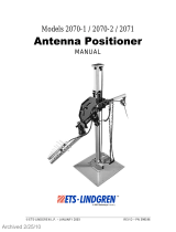
47.00 in
Mounting Fixture
Support Column
Centerline Height
60.00 in
Motor Base

13
PRE-INSTALLATION TASKS
Before installing any components, follow the safety information in the ETS-Lindgren Product
Information Bulletin included with your shipment.
Ensure power is o and base is secured before proceeding with installation.
Pre-planning is essential for successful installation. Discuss requirements with your sales representative and request
dimensional drawings prior to construction of your site.
Required Tools
• Flat-head screws for oor ange (not included)
• #2 Phillips screwdriver
ASSEMBLY AND INSTALLATION
Before installing any components, follow the safety information in the ETS-Lindgren Product
Information Bulletin included with your shipment.
Positioner Installation
Proper installation of the 2006 Precision Azimuth Positioner unit directly aects performance of the positioning
system as well as the accuracy of the test results.
1. Uncrate all parts. Check all parts for any shipping damage. Ensure a clear area is available to assemble the
positioner unit safely.
Do not discard packing material until the Turntable is fully assembled and correct operation is veried.
The 2006 Precision Azimuth Positioner consists of:
• Variable speed turntable
• Lossy foam absorber to cover the top of the turntable and enclosure
• Vertical column
Customer provides RF and USB cabling to the top of the unit and to the EUT.
2. The center of rotation for the unit must intersect the line through the bore sight of the measurement antenna. It
is recommended that a 5-beam laser level be utilized to verify the alignment and location.

14
3. Place the unit so the positioner connections are easily accessible and located closest to available feed through
panels and power supply connections. Ensure the Model 2006 is connected to a power outlet that
supplies 208-230VAC 50/60Hz. Use the power cord provided with the Model 2006 to make this connection
to the system.
US shipments will include a NEMA type 6-15P electrical plug power cord.
International shipments will include a Schuko type electrical plug power cord.
The IEC power inlet assembly includes a lter and an illuminated power switch.
4. Connect the positioner to the included Ethernet-to-ber optic converter using the included dual ber optic cable
with type ST connections. The converter connects to the host computer via the included 0.9 m (3.0 ft) Cat5
Ethernet cable. Ensure the ber converter TX line is connected to the positioner RX input connector, and the
ber converter RX line is connected to the positioner TX output connector.
5. The Model 2006 Azimuth Positioner is congured with multiple EUT connections tted with rotary joints to allow
continuous rotation of the EUT. The maximum AC power for the slip ring is 250 VAC 10 A. Power is supplied to
the system via an IEC power connection on the side of the 2006 unit. The IEC power connection includes a
power lter and a non-illuminated power switch.
Ensure all connections have been made correctly, and that the power connection for the motor
drive has not been confused with the power connection for the EUT. The 220 VAC motor
power inlet is operated by an illuminated switch, and the inlet for the customer’s EUT is
operated by a non-illuminated switch. Labels on the top surface of the motor base indicate the
location of each inlet.
A USB 2.0 connection is provided for the EUT through the rotary joint as well. A 2.4 mm coaxial rotary joint is
mounted at the center of the rotation axis. The rotary joint is rated to 26 GHz, and its connection can also be
found on the side of the 2006 unit.
Leveling
Pads
PROTECTIVE EARTH GROUNDING
Must be maintained on this
equipment to provide protect ion
from electrical shock
CAUTION
For continued protection against
FIRE HAZARD, replace fuse
only with fuse of the same type
and voltage rating
WARNING
Fuse: 10 A
Line Input: 120 - 240 V
Single Phase
50/60 Hz
2006
Precision Azimuth Positioner
EUT Power Input
ETS-Lindgren Inc.
1301 Arrow Point Dr.
Cedar Park, TX 78613
Made in USA
920943 Rev B

15
6. Once the unit is correctly positioned, the table must be leveled. Using a leveling instrument
(torpedo laser level or other leveling device) level the unit by turning the level mount pads on the bottom of the
motor base. When the unit is level, tighten all lock nuts on the leveling pads to lock the height of the unit
into place.
7. Place the center circular absorber piece over the support pegs.
8. Place the remaining two absorber pieces on the outer portion of the motor base.
9. Install the vertical support column onto the motor drive mount by placing it over the column supports on top of
the motor base.
10. Using gauge 126183, rotate the unit under power and indicate the gauge until it runs true. This can be adjusted
using the lock-nuts and column supports which are threaded. These are locate at the base of the column.
11. Floor absorber (ordered separately) may be placed around the motor base to prevent RF
interference from the positioner itself.
Electrical Installation
Electrical connection should only be performed by a qualied electrician and subject to
location electrical codes.
The Model 2006 Precision Azimuth Positioner is designed to operate using 208/230VAC single phase 50 or 60 Hz
AC power. The motor drive will not operate on a lower voltage, such as 110VAC. The power inlet assembly has an
integral 10 A fuse, however the branch circuit supplying power to the motor drive must be protected from excess
current according to local electrical codes. Normal current draw for the drive is less than 6 A.
Ensure the distance from the mains power source is appropriate for the wire gauge used and that the wire gauge is
adequate for the motor load.
Using undersized wire gauge will result in a higher than expected voltage drop in the power
conductors, reduced starting torque, and potentially premature motor failure.
Prior to servicing the turntable, remove the power connection.

16
Input / Output connections
Trigger
The positioner is equipped with a TTL-compatible output. This output is capable of driving a 50 ohm load that can
be used to trigger a measurement sweep on a network analyzer (or other measurement device equipped with a
TTL-compatible external trigger input option). The trigger BNC connector is located on the same side of the unit
as the 220 VAC motor power inlet.
Fiber Optic
The positioner is equipped with a ber-optic inlet and a ber-optic outlet. The ber-optic connectors are located
on the same side of the unit as the 220 VAC motor power inlet. Connect the positioner to the included Ethernet-
to-ber optic converter using the included dual ber optic cable with type ST connections. The converter connects
to the host computer via the included 0.9 m (3.0 ft) Cat5 Ethernet cable. Ensure the ber converter TX line is
connected to the positioner RX input connector, and the ber converter RX line is connected to the positioner TX
output connector.
Fiber-Optic In
Trigger In
Fiber-Optic Out

17
OPERATION
Before operating any components, follow the safety information in the ETS-Lindgren Product
Information Bulletin included with your shipment.
2006 Precision Azimuth Positioner Command Set
System Commands
Device Identication Query
Command: *IDN?
Description: Identication query. Determines the nature of device located at a given address
on the network. The string returned ("ETS-Lindgren Inc.,2006 Precision Azimuth
Positioner,<Module Name>,PCA120518 FW N.NN”) identies this device as a
2006 Precision Azimuth Positioner. The <Module Name> parameter is a place
holder to identify a specic module. The N.NN parameter is a place holder for the
rmware version identication.
Query: *IDN?
Returns: ETS-Lindgren Inc.,2006 Precision Azimuth Positioner,<Module
Name>,PCA120518 FW n.nn
Example: *IDN?
ETS-Lindgren Inc.,2006 Precision Azimuth Positioner,Comm,PCA120518 FW 4.14
Module IP Address
Command: MOD:IP <nnn.nnn.nnn.nnn>
Description: The device default IP address and subnet mask is 192.168.0.100, 255.255.255.0.
The default address and subnet mask are assigned to the device by ETS-Lindgren
and do not change even if your computer reboots. The IP address can be changed
using the MOD:IP command. The new address will not change even if your
computer reboots. The port number is 1206.
Query: MOD:IP?
Returns: nnn.nnn.nnn.nnn
Example: MOD:IP 192.168.0.55
Module Name
Command: MOD:NAME <Module Name>
Description: The <Module Name> parameter in the *IDN? query response is a place holder to
identify a specic device in a network. If you have more than one device you might
want to identify them with dierent module names. For instance, “EMC LAB1” and
“EMC CHAMBER”.
Query: MOD:NAME?
Example: MOD:NAME EMC LAB1

18
Module Subnet Mask
Command: MOD:NETMASK <nnn.nnn.nnn.nnn>
Description: The device default IP address and subnet mask is 192.168.0.100, 255.255.255.0.
This address and mask are assigned to the device by ETS-Lindgren and does not
change even if your computer reboots. The subnet mask can be changed using
the MOD:NETMASK command. The new subnet mask will not change even if
your computer reboots.
Query: MOD:NETMASK?
Returns: nnn.nnn.nnn.nnn
Example: MOD:NETMASK 255.255.0.0
Control Commands
Acceleration in Milliseconds
Command: A <nnnn>
Description: This is the acceleration setting for variable speed devices. The number nnnn
represents the time in milliseconds for the positioner to reach max speed. For
high inertial loads a longer acceleration time might be required.
Query: A?
Returns: The time in milliseconds for the positioner to reach max speed.
Example: A 3000
Acceleration in Seconds
Command: ACC nn.n
Description: This is the acceleration setting for variable speed devices. The number N.N
represents the time in seconds for the positioner to reach max speed. For high
inertial loads a longer acceleration time might be required.
Query: ACC?
Returns: The time in seconds for the positioner to reach max speed.
Example: ACC 3.0
Continuous Rotation Mode
Command: CR
Description: Set the positioner in continuous rotation mode. In the continuous mode of
operation the positioner is allowed innite movement. The turntable travels from
0 – 359.9 and the limits are ignored. Also, in continuous rotation mode, the device
will seek the target value by the shortest possible path. Thus, a seek from 350.0 to
10.0 will rotate clockwise, not counterclockwise.
Query: CR?
Returns: 1 when in continuous rotation mode, 0 otherwise
Example: CR

19
Homing Procedure
Command: HOME
Description: The device has a mechanical home sensor. Every time the positioner is turned
on, a home procedure must be performed so the current position is known by the
rmware.
To home the positioner, send the following commands:
HOME
*OPC?
Keep querying the positioner by sending the *OPC? until it returns 1.
*OPC? Will return 0 if the turntable is still being homed.
*OPC? will return 1 if the home procedure is done.
After *OPC returns 1, send the query HOME? to conrm that the positioner found
the mechanical home sensor.
HOME? returns 0 if the home procedure was not successful; the reason could be
a faulty sensor.
Query: HOME?
Returns: 1 if the positioner has been homed, 0 otherwise
Lower Limit
Command: LL nnn.n
Description: Sets the lower/counterclockwise limit of the device. The specied value nnn.n
must be less than the upper/clockwise limit.
Query: LL?
Returns: Lower or counterclockwise limit of the device in degrees.
Example: LL 0.0
Motion Direction
Command: DIR?
Description: Queries the motion direction for the device.
Query: DIR?
Returns: <direction> Value indicating the current motion of the queried device.
+1 Device is moving up/clockwise.
0 Device is stopped.
-1 Device is moving down/counterclockwise
Move Clockwise
Command: CW
Description: Instructs the positioner to move in the clockwise direction. In non-continuous
mode this movement is limited by the clockwise (upper) limit.
Example: CW
Move Counterclockwise
Command: CCW
Description: Instructs the positioner to move in the counterclockwise direction. This movement
is limited by the counterclockwise (lower) limit.

20
Move Counterclockwise
Example: CCW
Non-Continuous Rotation Mode
Command: NCR
Description: Set the positioner in non-continuous rotation mode. In the non-continuous mode
the positioner motion is restricted between the upper and lower limits. A seek from
350.0 to 10.0 will rotate Counterclockwise.
Example: NCR
Scan
Command: SCAN
Description: Instructs the positioner to begin scanning between preset lower and upper limits.
Example: SCAN
Seek Negative
Command: SKN <nnn.n>
Description: Instructs the device to begin seeking the specied target value in the negative
(down/counterclockwise) direction only. This command is provided primarily to
support continuous rotation mode. It allows forcing seeking a position from a
particular direction. Thus, a SKN from 180.0 to 181.0 will rotate counterclockwise
to reach the target value. In non-continuous rotation mode if the target is up/
clockwise from the current position, no motion occurs. The target must be located
between the current upper/clockwise and lower/counterclockwise limits.
Example: SKP 180.0
Seek Position
Command: SK nnn.n
Description: Instructs the device to begin seeking for a target position. In continuous rotation
mode, the device will seek the target value by the shortest possible path. Thus,
a seek from 350.0 to 10.0 will rotate clockwise, not direction. If the target is not
located between the current upper/clockwise and
lower/counterclockwise limits, motion will continue in the target direction until a
limit is hit.
Example: SK 60.0
Seek Positive
Command: SKP <nnn.n>
Description: Instructs the device to begin seeking the specied target value in the position
(up/clockwise) direction only. This command is provided primarily to support
continuous rotation mode. It allows forcing seeking a position from a particular
direction. Thus, a SKP from 181.0 to 180.0 will rotate clockwise to reach the target
value. In non-continuous rotation mode if the target is down/ counterclockwise
from the current position, no motion occurs. The target must be located between
the current upper/clockwise and lower/counterclockwise limits.
Example: SKP 180.0
/