Page is loading ...

Tomcat i7221 S5150 User’
s Manual
i
http://www.tyan.com
Tomcat i7221
///
S5150
Revision 1.02
Copyright © TYAN Computer Corporation, 2004. All rights reserved. No part of this manual
may be reproduced or translated without prior written consent from TYAN Computer Corp.
All registered and unregistered trademarks and company names contained in this manual are
property of their respective owners including, but not limited to the following.
TYAN, Tomcat, i7221 and S5150 are trademarks of TYAN Computer Corporation.
Intel Prescott and combinations thereof are trademarks of Intel Corporation.
Promise is a trademark of Promise Technology, Inc.
Award, AwardBIOS are trademarks of Award Software Incorporated.
Microsoft and Windows are trademarks of Microsoft Corporation.
IBM, PC, AT and PS/2 are trademarks of IBM Corporation.
Winbond is a trademark of Winbond Electronics Corporation.
SMSC is a trademark of Standard Microsystems Corporation.
Broadcom is a trademark of Broadcom Corporation.
Portable Document Format (PDF) is a trademark of Adobe Corporation.
Information contained in this document is furnished by TYAN Computer Corporation and has
been reviewed for accuracy and reliability prior to printing. TYAN assumes no liability
whatsoever, and disclaims any express or implied warranty, relating to sale and/or use of
TYAN products including liability or warranties relating to fitness for a particular purpose or
merchantability. TYAN retains the right to make changes to product descriptions and/or
specifications at any time, without notice. In no event will TYAN be held liable for any direct or
indirect, incidental or consequential damage, loss of use, loss of data or other malady resulting
from errors or inaccuracies of information contained in this document.

Tomcat i7221 S5150
Table of Contents
ii
http://www.tyan.com
Table of Contents
Before you begin….................................................................................................................v
Chapter 1: Introduction..........................................................................................................1
1.1 Congratulations!...........................................................................................................1
1.2 Hardware Specifications..............................................................................................1
Chapter 2: Board Installation.................................................................................................1
2.1 Installing the Motherboard............................................................................................1
2.1.1 Installation Notes ...............................................................................................1
2.2 Board Image ................................................................................................................2
2.3 Block Diagram..............................................................................................................3
2.4 Motherboard Components ...........................................................................................4
2.5 Jumpers and Connectors.............................................................................................5
2.5.1 Serial Port: COM2 (J5) ......................................................................................6
2.5.2 SO-DIMM Socket: J10.......................................................................................6
2.5.3 Serial ATA RAID Connectors: J19/J20/J21/J22 (SATA1 / SATA3 / SATA2 /
SATA4).......................................................................................................................7
2.5.4 LAN2/LAN1 Disabled Headers: JP1/JP2 ...........................................................7
2.5.5 Front Panel LAN1/LAN2 Link and Active LED Connector: JP3/JP6...................8
2.5.6 Chassis Fan Connector: JP4 .............................................................................8
2.5.7 Front Panel LAN1/LAN2 Speed LED Pin-Header: JP5/JP7 ...............................9
2.5.8 CPU Fan Connector: JP9 (P1FAN) ...................................................................9
2.5.9 Front Panel USB 2.0 Connector: JP11/JP12 ...................................................10
2.5.10 Clear CMOS Jumper: JP13 ...........................................................................10
2.5.11 Front Panel System Connector: JP14............................................................11
2.5.12 Front Fan Connector: JP15/JP17/JP21 (FAN2/FAN6/FAN4).........................11
2.5.13 Chassis Fan Connector: JP16 (FAN1)...........................................................12
2.5.14 SMDC Connector: JP19 (Optional)................................................................12
2.5.15 PCI-X Speed Select Header: JP20................................................................13
2.5.16 SMDC/ASF2.0 Select Header:JP22/JP23 .....................................................13
2.6 Mounting the Motherboard.........................................................................................14
2.7 Installing Memory.......................................................................................................15
2.7.1 Memory Installation Procedure........................................................................16
2.8 Installing the Processor and Cooling Fan...................................................................16
2.9 Installing Drive Cables ...............................................................................................19
2.10 Installing Expansion Cards.......................................................................................20
2.11 Connecting External Devices...................................................................................21
2.11.1 Onboard LAN LED Color Definition ...............................................................21
2.12 Installing the Power Supply......................................................................................22
2.13 Finishing Up .............................................................................................................22
Chapter 3: BIOS Setup............................................................................................................1
3.1 About the BIOS............................................................................................................1
3.1.1 Starting Setup....................................................................................................1
3.1.2 Setup Basics......................................................................................................1
3.1.3 Getting Help.......................................................................................................1
3.1.4 In Case of Problems ..........................................................................................2
3.1.5 Setup Variations................................................................................................2
3.2 Main BIOS Setup .........................................................................................................2
3.3 Standard CMOS Features............................................................................................4
3.4 Advanced BIOS Features............................................................................................5
3.4.1 CPU Features....................................................................................................7
3.4.2 Boot Sequence................................................................................................10
3.4.3 Console Redirection........................................................................................12
3.5 Advanced Chipsets Features.....................................................................................12

Tomcat i7221 S5150
Table of Contents
iii
http://www.tyan.com
3.5.1 PCI Express Root Port Function......................................................................14
3.6 Integrated Peripherals................................................................................................16
3.6.1 OnChip IDE Device..........................................................................................16
3.6.2 Onboard Device...............................................................................................18
3.6.3 Super IO Device..............................................................................................19
3.7 Power Management Setup.........................................................................................21
3.7.1 PCI Express PM Function................................................................................23
3.7.2 Power On Setup..............................................................................................24
3.7.3 Reload Global Timer Events............................................................................25
3.8 PnP/PCI Configurations.............................................................................................26
3.8.1 IRQ Resources................................................................................................27
3.9 PC Health Status .......................................................................................................28
3.10 Frequency/Voltage Control......................................................................................28
3.11 Load Fail-Safe Defaults............................................................................................30
3.12 Load Optimized Defaults..........................................................................................30
3.13 Supervisor/User Password Setting...........................................................................31
3.14 Save & Exit Setup....................................................................................................32
3.15 Exit Without Saving..................................................................................................32
Chapter 4: SATA/RAID Setup (for SATA RAID model).........................................................1
4.1 Configuring BIOS for Intel RAID for Serial ATA on board.............................................1
4.1.1 Creating, Deleting, and Resetting RAID Sets ....................................................1
4.1.2 Create RAID 0 or RAID 1 Volume......................................................................1
4.1.3 Delete RAID Volume..........................................................................................2
4.1.4 Reset RAID Data...............................................................................................2
4.2 Loading the Intel Application Accelerator RAID Edition Driver During Operating
System Install.....................................................................................................................2
4.2.1 Instructions on Creating F6 Floppy Diskette......................................................3
4.2.2 Installation Using F6 Method .............................................................................3
4.3 Intel RAID Option ROM................................................................................................4
4.3.1 Description.........................................................................................................4
4.3.2 Confirming Version of Intel RAID Option ROM Installed....................................4
4.3.3 Using the Intel RAID Option ROM.....................................................................4
4.4 Installing the Intel Application Accelerator RAID Edition ............................................10
4.4.1 Installation Caution..........................................................................................10
4.4.2 Steps to Take Before Installing the Intel Application Accelerator RAID Edition 10
4.4.3 Obtaining and Installing the Intel Application Accelerator RAID Edition...........11
4.5 Confirming the Intel Application Accelerator RAID Edition is Installed .......................14
4.6 Confirming Version of Intel Application Accelerator RAID Edition Installed................15
4.6.1 Using the Intel Application Accelerator RAID Edition Utility:............................15
4.6.2 RAID Driver File Properties:.............................................................................15
4.7 Issues During Installation...........................................................................................16
4.7.1 Symptom: Incompatible Hardware...................................................................16
4.7.2 Symptom: Unable to launch Intel(R ) Application Accelerator Readme file......16
4.8 “RAID Ready”.............................................................................................................16
4.8.1 “RAID Ready” Definition ..................................................................................16
4.8.2 “RAID Ready” System Requirements ..............................................................16
4.8.3 Steps on Setting Up a “RAID Ready” System..................................................16
4.8.4 Converting a “RAID Ready” System into RAID 0 or RAID 1 System with
Migration Feature .....................................................................................................17
4.9 RAID Migration Instructions.......................................................................................18
4.9.1 Create RAID Volume from Existing Hard Drive................................................19
4.9.2 Migration Process May Take Considerable Time to Complete ........................22
4.10 Uninstalling the Intel Application Accelerator RAID Edition......................................23
4.10.1 Uninstall Warning...........................................................................................23

Tomcat i7221 S5150
Table of Contents
iv
http://www.tyan.com
4.10.2 Windows* 2003 / Windows 2000...................................................................23
4.11 Unattended Installation Under Windows* 2003 / Windows 2000..............................24
4.12 Intel Storage Utility...................................................................................................24
4.12.1 Description.....................................................................................................24
4.12.2 Create Volume Manually................................................................................25
4.12.3 Successful Creation.......................................................................................28
4.13 Configure BIOS for Adaptec RAID for Serial ATA on Board.....................................28
4.13.1 BIOS Configuration........................................................................................28
4.13.2 Installing Serial ATA (SATA) hard disks.........................................................29
4.13.3 Adaptec RAID Configuration Utility ................................................................29
4.13.4 Manage Array................................................................................................30
4.13.5 Create Array ..................................................................................................31
4.13. 6 Add/Delete Hotspare....................................................................................33
4.13.7 Initialize Drives...............................................................................................33
4.13.8 Disk Utilities ...................................................................................................34
Chapter 5: Diagnostics...........................................................................................................1
5.1 Beep Codes.................................................................................................................1
5.2 Flash Utility ..................................................................................................................1
Appendix I: Glossary..............................................................................................................1
Appendix II: Post Error Code for BIOS..................................................................................7
Technical Support.................................................................................................................12

Tomcat i7221 S5150 Before you begin…
v
http://www.tyan.com
Before you begin…
Check the package contents before you proceed.
The retail motherboard package should contain the following:
1 x Tomcat i7221 S5150 motherboard
1 x 34-Pin floppy drive cable
1 x Ultra-DMA-133/100/66/33 IDE cable
1 x Tomcat i7221 S5150 User’s Manual
1 x Tomcat i7221 S5150 Quick Reference Guide
1 x TYAN driver CD
1 x Intel 82801FR (ICH6R) Driver Diskette
1 x Adaptec Driver Diskette
1 x I/O shield
2 x Serial ATA power cable
4 x Serial ATA cable
1 x USB2.0 cable
If any of these items are missing, please contact your vendor or dealer for replacement before
continuing with the installation process.

Tomcat i7221 S5150
Chapter 1: Introduction
1-1
http://www.tyan.com
Chapter 1: Introduction
1.1 Congratulations!
Congratulations on your purchase of the TYAN Tomcat i7221 S5150, one of the most powerful
and versatile motherboard solutions available for Intel Prescott processors. Based on the
acclaimed Intel i7221 GMCH chipset, the S5150 offers exceptional performance and
outstanding features. With the x1 PCI Express slots, onboard two Gigabit Ethernet port, Serial
ATA RAID, four Dual-channel DDR DIMM sockets, plus the optional SCSI, four port and eight
port Serial ATA modules, the Tomcat i7221 S5150 is fast and flexible enough to fit your
server/workstation needs.
For more information about this and other TYAN products, visit the TYAN Web site at
http://www.tyan.com. Product FAQs, a list of distributors and advanced BIOS information are
also available on the Web site.
1.2 Hardware Specifications
Processors
Ÿ Single Socket-T (LGA775 socket)
Ÿ Intel
“Prescott” processor with EM64T
support
Ÿ 800/533MHz FSB support
Expansion Slots
Ÿ PCI-X 64-bit 133/100/66MHz bus supports
with
? One PCI-X slot (maximum of 100MHz
w/ riser card application)
? One proprietary 200-pin SO-DIMM
connector
Ÿ Two x1 PCI Express connectors
Ÿ One 32-bit, 33MHz PCI v2.3 slots
Ÿ Five total usable expansion slots/connectors
Chipset
Ÿ Intel E7221 GMCH
Ÿ Intel ICH6R South Bridge
Ÿ Intel PXH-V I/O bridge
Ÿ SMSC DME1737 Super I/O
System Management
Ÿ SMSC DME1737 w/ hardware monitoring
Ÿ One 3+1-pin CPU Fan header w/
tachometer input and temperature-sensing
auto fan control
Ÿ Four 3-pin system Fan headers (two w/
tachometer input and temperature-sensing
auto fan control)
Ÿ Temperature and voltage monitoring
Ÿ Watchdog timer
Ÿ Port 80 code display LED
Integrated I/O Interface
Ÿ One floppy connector
Ÿ Four USB 2.0 ports (via cable)
Ÿ One COM2 port (via cable)
Ÿ One LPT port (via cable)
Ÿ Power/IDE/SATA LED connectors
Ÿ Two 2+2-pin headers for front panel
LAN LED
Ÿ TYAN 2 x 9 front-panel pin header
Integrated LAN Controllers
Ÿ Two GbE LAN controllers
? Two Broadcom BCM5721 PCI
Express GbE LAN controller
? Operating at x1 PCI-E interface
? ASF 2.0 support
? Pin headers for front panel LAN
LED
Optional modules
Ÿ M7901/M7902, SO-DIMM Ultra 320
SCSI card
? Adaptec AIC-7901/7902 single/dual-
channel Ultra 320 SCSI controller
? Adaptec HostRAID support w/RAID
0, 1, 10 supported
Ÿ M8110/M8120 SO-DIMM SATA card
? Adaptec AIC-8110/8120 SATA
controller
? Support up to 4-port (M8110) and 8-
port (M8120) SATA ports running at
1.5GB/s
? Adaptec HostRAID support with
RAID 0, 1, 10 supported

Tomcat i7221 S5150
Chapter 1: Introduction
1-2
http://www.tyan.com
Memory
Ÿ Dual memory channels
Ÿ Supports Up to four DDR-333/400 DIMM
Ÿ Up to 4GB of Non-Reg/ECC or Non-
Reg/Non-ECC memory
Intelligent PCI IDE (ICH6R)
Ÿ Single channel master mode supports two
IDE devices
Ÿ Support for ATA-100/66/33 IDE drives and
ATAPI compliant devices
Integrated Serial ATA (ICH6R)
Ÿ Four Serial ATA Host controllers embedded
Ÿ Support four Serial ports running at 1.5Gb/s
Ÿ RAID 0, 1 support
Integrated PCI Graphic
Ÿ 8-bit VGA DAC embedded the MCH to
support an analog display
Rear Panel I/O ports
Ÿ Stacked PS/2 Mouse & Keyboard ports
Ÿ Stacked two USB2.0 ports
Ÿ One 15-pin VGA port
Ÿ One 9-pin COM port
Ÿ Six audio jacks (optional)
Ÿ Two RJ45 10/100/1000 Base-T port w/
activity LED
BIOS
Ÿ Award BIOS 8Mbit Flash ROM
Ÿ Support APM 1.2 & ACPI 1.0B
Ÿ PnP, DNI 2.0, WFM 2.0 Power
Management
Power
Ÿ EPS12V support, on board 4-phase
VRM
Ÿ Universal 24-pin + 8-pin or 20-pin + 4-
pin power connectors
Form Factor
Ÿ ATX footprint
Ÿ 12” x 9.6” (305mm x 245mm)
Regulatory
Ÿ FCC Class B (Declaration of
Conformity)
Ÿ CE (Declaration of Conformity)
Ÿ BSMI
Note
TYAN reserves the right to add support or discontinue support for any OS
with or without notice.

Tomcat i7221 S5150 Chapter 2: Board Installation
2-1
http://www.tyan.com
Chapter 2: Board Installation
2.1 Installing the Motherboard
The Tomcat i7221 S5150 motherboard conforms fully to the ATX specification. Before
continuing with the installation, confirm that your chassis supports a standard ATX
motherboard. If you are unsure, contact your dealer for more information.
2.1.1 Installation Notes
This user manual contains important information and you should read it thoroughly before
attempting the installation procedure.
Precautions:
• Static electricity can damage components on your motherboard. Before touching the
product, discharge any static build up in yourself by touching a well grounded object
such as a metal water pipe or a grounded electrical appliance. TYAN recommends
putting on a good quality grounded wrist strap before removing your motherboard from
the antistatic bag.
• Disconnect your computer from the power supply before any disassembly procedure is
attempted.
• Touch the motherboard as little as possible and do not touch the bottom of the board at
• all. Bending or flexing the motherboard may break delicate components or copper tracks
on the board.
• Avoid touching any of the motherboard components.
• Place the motherboard on a grounded antistatic surface or on the antistatic bag in which
the board was shipped.
• Inspect the board for damage.
Read the following sections for detailed instructions on how to install your motherboard in a
chassis and add a processor, memory, and disk drives.
Warning
Do not apply power to the board if it appears damaged.

Tomcat i7221 S5150 Chapter 2: Board Installation
2-2
http://www.tyan.com
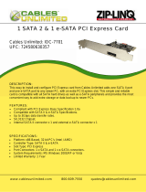
2.2 Board Image
The following is an image of the Tomcat i7221 S5150.
The above photograph is purely representative. Due to engineering updates and new
board revisions, certain components may change and or be repositioned. The picture
above may or may not look exactly like the board you received.
The following page includes details on the vital components of this motherboard.

Tomcat i7221 S5150 Chapter 2: Board Installation
2-3
http://www.tyan.com
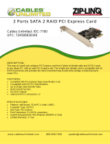
2.3 Block Diagram
The following is a block diagram of the Tomcat i7221 S5150.
PRESCOTT
LGA775
CPU
VRM
Intel
E7221
GMCH
Intel
ICH6R
DIMM1
PXH-V
SUPER-I/O
DME1737
ATA 100 IDE X 1
800 MHz SYSTEM BUS
MD/MA
PCI
EXPRESS
DMI BUS
DIMM2
DIMM3
DIMM4
133MHz OR
100MHz PCI-X
133MHz OR
100MHz PCI-X
SATA X 4 PORT
USB 2.0 X 6 PORT
PRINTER
PORT
SERIAL
PORT
SERIAL
PORT
KBD
PORT
FLOPPY
CONN
BIOS
8Mb
10/100/1000
LAN B
BCM5721
RJ45
MD/MB
DDR 333/400
DDR B DIMMS
DDR 333/400
DDR A DIMMS
PCI1
LPC BUS
FIRMWARE HUB
SO DIMM
PCI-X
CLOCK
CHIP
PCI 32/33MHz
10/100/1000
LAN A
BCM5721
RJ45
PCI E1
PCI E2
VGA
CONNECTOR
PCI E-1 / PCI E-2

Tomcat i7221 S5150 Chapter 2: Board Installation
2-4
http://www.tyan.com
2.4 Motherboard Components
The diagram below shows the main motherboard components.
1
1
1
1
PW2
P1FAN
JP9
BIOS
JP17
Intel
E7221
Intel
ICH6R
PCI-E1
SATA2
SATA1
FDD J9
JP20
IDE J13
DIMM3
DIMM2
DIMM1
1
SMSC
I/O
BT1
DIMM4
PCI-E2
1
LED1
SATA3
SATA4
FAN6
BROADCOM
LAN
(Optional)
1
JP16
JP10
1
JP13
1
JP15
S5150
KB(Bottom)
Mouse(Top)
JP11 JP12
BROADCOM
LAN
(Optional)
JP6
1
JP3
1
SMDC JP19
1
JP4
J5
32-bit 33MHz (5V) PCI J11
SO_DIMM J10
64-bit 100MHz PCI-X J12
J4
USB1
J1
KB / MS
J3
(COM1)
J2
(VGA)
LAN1
LAN2
LPT J8
Intel
PXH
JP7
1
JP5
1
JP2
1
JP1
1
1
JP21
1
JP22
1
JP23
This diagram represents the latest version of the motherboard available at the time of
publishing. The board you receive may or may not look exactly like the above diagram.
Parts are not drawn to scale.

Tomcat i7221 S5150 Chapter 2: Board Installation
2-5
http://www.tyan.com
2.5 Jumpers and Connectors
Jumpers and pin headers are provided on your motherboard for configuration and connection
to peripherals. The following section shows you how to set your jumpers and use your pin
headers.
Connector Function Ref. Page
J5 COM2 port Page 2-6
J8 Printer port connector
J9 Floppy disk drive connector
J10 SO-DIMM socket Page 2-6
J13 IDE connector
J19/J20/J21/J22 Serial ATA connectors Page 2-7
J23** Reserved
JP1/JP2 LAN2/LAN1 disabled headers Page 2-7
JP3/JP6
Front panel LAN1/LAN2 link/activity LED
connector
Page 2-8
JP4 (FAN1) Chassis fan connector Page 2-8
JP5/JP7 Front Panel LAN2/LAN1 speed LED headers Page 2-9
JP9 (P1FAN) CPU fan connector with tachometer input Page 2-9
JP10** Reserved Page 2-9
JP11/JP12 Front panel USB connector Page 2-10
JP13 Clear CMOS jumper Page 2-10
JP14 Front panel system connector Page 2-11
JP15/JP17/JP21 Front fan connector with tachometer input Page 2-11
JP16 Chassis f an connector Page 2-12
JP19* SMDC connector (optional) Page 2-12
JP20 PCI-X speed select header Page 2-13
* Some jumpers and headers are optional and not available with the board due to the different
configurations.
** J23 and JP10 are reserved for OEM use only.
Jumper Legend
Jumper OFF – open (without jumper cap)
Jumper ON – closed (with jumper cap)

Tomcat i7221 S5150 Chapter 2: Board Installation
2-6
http://www.tyan.com
2.5.1 Serial Port: COM2 (J5)
10 2
9 1
Signal Description
GND
(Ground)
DTR
(Data-Terminal-Ready)
TX
(Transfer-Data)
RX
(Receive-Data)
DCD
(Data Carrier Detect)
Pin#
9 7 6 3
1
Pin#
10 8 5 4
2
PW2
P1FAN
JP9
BIOS
JP17
Intel
E7221
Intel
ICH6R
PCI-E1
SATA2
SATA1
FDD J9
JP20
IDE J13
DIMM3
DIMM2
DIMM1
SMSC
I/O
BT1
DIMM4
PCI-E2
LED1
SATA3
SATA4
FAN6
BROADCOM
LAN
(Optional)
JP16
JP10
JP13
JP15
S5150
KB(Bottom)
Mouse(Top)
JP11 JP12
BROADCOM
LAN
(Optional)
JP6
JP3
SMDC JP19
JP4
J5
32-bit 33MHz (5V) PCI J11
SO_DIMM J10
64-bit 100MHz PCI-X J12
J4
USB1
J1
KB / MS
J3
(COM1)
J2
(VGA)
LAN1
LAN2
LPT J8
Intel
PXH
JP7
JP5
JP2
JP1
JP21
JP22
JP23
Signal Description
NC/Key
RI
(Ring-Indicator)
CTS
(Clear-to-Send)
RTS
(Request-to- Send)
DSR
(Data-Set-Ready)
2.5.2 SO-DIMM Socket: J10
PW2
P1FAN
JP9
BIOS
JP17
Intel
E7221
Intel
ICH6R
PCI-E1
SATA2
SATA1
FDD J9
JP20
IDE J13
DIMM3
DIMM2
DIMM1
SMSC
I/O
BT1
DIMM4
PCI-E2
LED1
SATA3
SATA4
FAN6
BROADCOM
LAN
(Optional)
JP16
JP10
JP13
JP15
S5150
KB(Bottom)
Mouse(Top)
JP11 JP12
BROADCOM
LAN
(Optional)
JP6
JP3
SMDC JP19
JP4
J5
32-bit 33MHz (5V) PCI J11
SO_DIMM J10
64-bit 100MHz PCI-X J12
J4
USB1
J1
KB / MS
J3
(COM1)
J2
(VGA)
LAN1
LAN2
LPT J8
Intel
PXH
JP7
JP5
JP2
JP1
JP21
JP22
JP23
Connect SCSI Daughter Card
Compatible with Tyan M7902
J5
J10

Tomcat i7221 S5150 Chapter 2: Board Installation
2-7
http://www.tyan.com
2.5.3 Serial ATA RAID Connectors: J19/J20/J21/J22 (SATA1 / SATA3 / SATA2 / SATA4)
7 GND
6 RXP
5 RX N
4 GND
3 TXN
2 TXP
7
1
1 GND
PW2
P1FAN
JP9
BIOS
JP17
Intel
E7221
Intel
ICH6R
PCI-E1
SATA2
SATA1
FDD J9
JP20
IDE J13
DIMM3
DIMM2
DIMM1
SMSC
I/O
BT1
DIMM4
PCI-E2
LED1
SATA3
SATA4
FAN6
BROADCOM
LAN
(Optional)
JP16
JP10
JP13
JP15
S5150
KB(Bottom)
Mouse(Top)
JP11 JP12
BROADCOM
LAN
(Optional)
JP6
JP3
SMDC JP19
JP4
J5
32-bit 33MHz (5V) PCI J11
SO_DIMM J10
64-bit 100MHz PCI-X J12
J4
USB1
J1
KB / MS
J3
(COM1)
J2
(VGA)
LAN1
LAN2
LPT J8
Intel
PXH
JP7
JP5
JP2
JP1
JP21
JP22
JP23
Connects to the Serial ATA ready drives
via the Serial ATA cable
You may use any two of the four Serial
ATA ports to have the support of RAID 0
and 1 through the on board ICH6R south
bridge chip.
2.5.4 LAN2/LAN1 Disabled Headers: JP1/JP2
1
OPEN: Disabled
PW2
P1FAN
JP9
BIOS
JP17
Intel
E7221
Intel
ICH6R
PCI-E1
SATA2
SATA1
FDD J9
JP20
IDE J13
DIMM3
DIMM2
DIMM1
SMSC
I/O
BT1
DIMM4
PCI-E2
LED1
SATA3
SATA4
FAN6
BROADCOM
LAN
(Optional)
JP16
JP10
JP13
JP15
S5150
KB(Bottom)
Mouse(Top)
JP11 JP12
BROADCOM
LAN
(Optional)
JP6
JP3
SMDC JP19
JP4
J5
32-bit 33MHz (5V) PCI J11
SO_DIMM J10
64-bit 100MHz PCI-X J12
J4
USB1
J1
KB / MS
J3
(COM1)
J2
(VGA)
LAN1
LAN2
LPT J8
Intel
PXH
JP7
JP5
JP2
JP1
JP21
JP22
JP23
1
CLOSED: Enabled (Default)
SATA
JP2
JP1

Tomcat i7221 S5150 Chapter 2: Board Installation
2-8
http://www.tyan.com
2.5.5 Front Panel LAN1/LAN2 Link and Active LED Connector: JP3/JP6
JP3
1
Pin 1: LED+
Pin 2: LED-
JP6
1
Pin 1: LED+
Pin 2: LED-
PW2
P1FAN
JP9
BIOS
JP17
Intel
E7221
Intel
ICH6R
PCI-E1
SATA2
SATA1
FDD J9
JP20
IDE J13
DIMM3
DIMM2
DIMM1
SMSC
I/O
BT1
DIMM4
PCI-E2
LED1
SATA3
SATA4
FAN6
BROADCOM
LAN
(Optional)
JP16
JP10
JP13
JP15
S5150
KB(Bottom)
Mouse(Top)
JP11 JP12
BROADCOM
LAN
(Optional)
JP6
JP3
SMDC JP19
JP4
J5
32-bit 33MHz (5V) PCI J11
SO_DIMM J10
64-bit 100MHz PCI-X J12
J4
USB1
J1
KB / MS
J3
(COM1)
J2
(VGA)
LAN1
LAN2
LPT J8
Intel
PXH
JP7
JP5
JP2
JP1
JP21
JP22
JP23
Use these headers to connect with the
front panel link/activity LEDs for LAN1 and
LAN2.
2.5.6 Chassis Fan Connector: JP4
+12V
GND
NC
PW2
P1FAN
JP9
BIOS
JP17
Intel
E7221
Intel
ICH6R
PCI-E1
SATA2
SATA1
FDD J9
JP20
IDE J13
DIMM3
DIMM2
DIMM1
SMSC
I/O
BT1
DIMM4
PCI-E2
LED1
SATA3
SATA4
FAN6
BROADCOM
LAN
(Optional)
JP16
JP10
JP13
JP15
S5150
KB(Bottom)
Mouse(Top)
JP11 JP12
BROADCOM
LAN
(Optional)
JP6
JP3
SMDC JP19
JP4
J5
32-bit 33MHz (5V) PCI J11
SO_DIMM J10
64-bit 100MHz PCI-X J12
J4
USB1
J1
KB / MS
J3
(COM1)
J2
(VGA)
LAN1
LAN2
LPT J8
Intel
PXH
JP7
JP5
JP2
JP1
JP21
JP22
JP23
Use this header to connect the chassis
cooling fan to your motherboard to keep
the system stable and reliable.
JP3
JP6
JP4

Tomcat i7221 S5150 Chapter 2: Board Installation
2-9
http://www.tyan.com
2.5.7 Front Panel LAN1/LAN2 Speed LED Pin-He ader: JP5/JP7
1
Pin 2: Green+
Pin 1: Orange+
PW2
P1FAN
JP9
BIOS
JP17
Intel
E7221
Intel
ICH6R
PCI-E1
SATA2
SATA1
FDD J9
JP20
IDE J13
DIMM3
DIMM2
DIMM1
SMSC
I/O
BT1
DIMM4
PCI-E2
LED1
SATA3
SATA4
FAN6
BROADCOM
LAN
(Optional)
JP16
JP10
JP13
JP15
S5150
KB(Bottom)
Mouse(Top)
JP11 JP12
BROADCOM
LAN
(Optional)
JP6
JP3
SMDC JP19
JP4
J5
32-bit 33MHz (5V) PCI J11
SO_DIMM J10
64-bit 100MHz PCI-X J12
J4
USB1
J1
KB / MS
J3
(COM1)
J2
(VGA)
LAN1
LAN2
LPT J8
Intel
PXH
JP7
JP5
JP2
JP1
JP21
JP22
JP23
Use these headers to connect with the
front panel dual color LEDs to indicate the
speed of LAN1 and LAN2.
Off=10 LAN,
Green=100 LAN,
Orange=GbE LAN
Reference Section 2.11.1 for the correct
LAN LED Color Definition.
JP5 is for LAN1, JP7 is for LAN2.
2.5.8 CPU Fan Connector: JP9 (P1FAN)
+12V
V3P3
Speed Control
Tachometer
PW2
P1FAN
JP9
BIOS
JP17
Intel
E7221
Intel
ICH6R
PCI-E1
SATA2
SATA1
FDD J9
JP20
IDE J13
DIMM3
DIMM2
DIMM1
SMSC
I/O
BT1
DIMM4
PCI-E2
LED1
SATA3
SATA4
FAN6
BROADCOM
LAN
(Optional)
JP16
JP10
JP13
JP15
S5150
KB(Bottom)
Mouse(Top)
JP11 JP12
BROADCOM
LAN
(Optional)
JP6
JP3
SMDC JP19
JP4
J5
32-bit 33MHz (5V) PCI J11
SO_DIMM J10
64-bit 100MHz PCI-X J12
J4
USB1
J1
KB / MS
J3
(COM1)
J2
(VGA)
LAN1
LAN2
LPT J8
Intel
PXH
JP7
JP5
JP2
JP1
JP21
JP22
JP23
Use this header to connect the processor
cooling fan to your motherboard to keep
the system stable and reliable.
JP5
JP7
JP9

Tomcat i7221 S5150 Chapter 2: Board Installation
2-10
http://www.tyan.com
2.5.9 Front Panel USB 2.0 Connector: JP11/JP12
10 2
9 1
NC/Key
GND
Data 1+
Data 1 -
+5V
9 7 5 3 1
10 8 6 4 2
GND
GND
Data 2+
Data 2 -
+5V
PW2
P1FAN
JP9
BIOS
JP17
Intel
E7221
Intel
ICH6R
PCI-E1
SATA2
SATA1
FDD J9
JP20
IDE J13
DIMM3
DIMM2
DIMM1
SMSC
I/O
BT1
DIMM4
PCI-E2
LED1
SATA3
SATA4
FAN6
BROADCOM
LAN
(Optional)
JP16
JP10
JP13
JP15
S5150
KB(Bottom)
Mouse(Top)
JP11 JP12
BROADCOM
LAN
(Optional)
JP6
JP3
SMDC JP19
JP4
J5
32-bit 33MHz (5V) PCI J11
SO_DIMM J10
64-bit 100MHz PCI-X J12
J4
USB1
J1
KB / MS
J3
(COM1)
J2
(VGA)
LAN1
LAN2
LPT J8
Intel
PXH
JP7
JP5
JP2
JP1
JP21
JP22
JP23
Use these headers to Connect to the USB
devices via the enclosed USB cable.
2.5.10 Clear CMOS Jumper: JP13
3
1
Default
3
1
Clear
PW2
P1FAN
JP9
BIOS
JP17
Intel
E7221
Intel
ICH6R
PCI-E1
SATA2
SATA1
FDD J9
JP20
IDE J13
DIMM3
DIMM2
DIMM1
SMSC
I/O
BT1
DIMM4
PCI-E2
LED1
SATA3
SATA4
FAN6
BROADCOM
LAN
(Optional)
JP16
JP10
JP13
JP15
S5150
KB(Bottom)
Mouse(Top)
JP11 JP12
BROADCOM
LAN
(Optional)
JP6
JP3
SMDC JP19
JP4
J5
32-bit 33MHz (5V) PCI J11
SO_DIMM J10
64-bit 100MHz PCI-X J12
J4
USB1
J1
KB / MS
J3
(COM1)
J2
(VGA)
LAN1
LAN2
LPT J8
Intel
PXH
JP7
JP5
JP2
JP1
JP21
JP22
JP23
Use this jumper when you forgot your
system/setup password or need to clear
system BIOS setting.
How to clear the CMOS data
- Power off system and disconnect
power supply from AC source
- Use jumper cap to close Pin_2 and 3
for several seconds to Clear CMOS
- Replace jumper cap to close Pin_1
and 2 (default setting)
- Reconnect power supply to AC
source
Power on system
JP11
JP12
JP13

Tomcat i7221 S5150 Chapter 2: Board Installation
2-11
http://www.tyan.com
2.5.11 Front Panel System Connector: JP14
Your chassis will usually come with connectors to install onto the motherboard, such as HD
and Power LEDs. The Front Panel Connector (JP14) has been implemented for such
purposes.
1 2
17 18
Function PIN PIN Function
HD_LED+
1 2
PWR+
HD_LED-
3 4
PWR-
GND
5 6
Power Button
Reset
Button
7 8
GND
+5V
9 10
NC
NIMI
11 12
GND
+5VSB
13 14
NC
SMBUS
Data
15 16
GND
PW2
P1FAN
JP9
BIOS
JP17
Intel
E7221
Intel
ICH6R
PCI-E1
SATA2
SATA1
FDD J9
JP20
IDE J13
DIMM3
DIMM2
DIMM1
SMSC
I/O
BT1
DIMM4
PCI-E2
LED1
SATA3
SATA4
FAN6
BROADCOM
LAN
(Optional)
JP16
JP10
JP13
JP15
S5150
KB(Bottom)
Mouse(Top)
JP11 JP12
BROADCOM
LAN
(Optional)
JP6
JP3
SMDC JP19
JP4
J5
32-bit 33MHz (5V) PCI J11
SO_DIMM J10
64-bit 100MHz PCI-X J12
J4
USB1
J1
KB / MS
J3
(COM1)
J2
(VGA)
LAN1
LAN2
LPT J8
Intel
PXH
JP7
JP5
JP2
JP1
JP21
JP22
JP23
SMBUS
Clock
17 18
INTRU#
2.5.12 Front Fan Connector: JP15/JP17/JP21 (FAN2/FAN6/FAN4)
JP15 (FAN2)/JP21 (FAN4)
+12V
Speed Control
Tachometer
JP17 (FAN6)
+12V
Speed Control
Tachometer
PW2
P1FAN
JP9
BIOS
JP17
Intel
E7221
Intel
ICH6R
PCI-E1
SATA2
SATA1
FDD J9
JP20
IDE J13
DIMM3
DIMM2
DIMM1
SMSC
I/O
BT1
DIMM4
PCI-E2
LED1
SATA3
SATA4
FAN6
BROADCOM
LAN
(Optional)
JP16
JP10
JP13
JP15
S5150
KB(Bottom)
Mouse(Top)
JP11 JP12
BROADCOM
LAN
(Optional)
JP6
JP3
SMDC JP19
JP4
J5
32-bit 33MHz (5V) PCI J11
SO_DIMM J10
64-bit 100MHz PCI-X J12
J4
USB1
J1
KB / MS
J3
(COM1)
J2
(VGA)
LAN1
LAN2
LPT J8
Intel
PXH
JP7
JP5
JP2
JP1
JP21
JP22
JP23
Use these headers to connect the chassis
cooling fans to your motherboard to keep
the system stable and reliable.
JP14
JP17
JP21
JP15

Tomcat i7221 S5150 Chapter 2: Board Installation
2-12
http://www.tyan.com
2.5.13 Chassis Fan Connector: JP16 (FAN1)
+12V
Speed Control
GND
PW2
P1FAN
JP9
BIOS
JP17
Intel
E7221
Intel
ICH6R
PCI-E1
SATA2
SATA1
FDD J9
JP20
IDE J13
DIMM3
DIMM2
DIMM1
SMSC
I/O
BT1
DIMM4
PCI-E2
LED1
SATA3
SATA4
FAN6
BROADCOM
LAN
(Optional)
JP16
JP10
JP13
JP15
S5150
KB(Bottom)
Mouse(Top)
JP11 JP12
BROADCOM
LAN
(Optional)
JP6
JP3
SMDC JP19
JP4
J5
32-bit 33MHz (5V) PCI J11
SO_DIMM J10
64-bit 100MHz PCI-X J12
J4
USB1
J1
KB / MS
J3
(COM1)
J2
(VGA)
LAN1
LAN2
LPT J8
Intel
PXH
JP7
JP5
JP2
JP1
JP21
JP22
JP23
Use this header to connect the chassis
cooling fans to your motherboard to keep
the system stable and reliable.
2.5.14 SMDC Connector: JP19 (Optional)
PW2
P1FAN
JP9
BIOS
JP17
Intel
E7221
Intel
ICH6R
PCI-E1
SATA2
SATA1
FDD J9
JP20
IDE J13
DIMM3
DIMM2
DIMM1
SMSC
I/O
BT1
DIMM4
PCI-E2
LED1
SATA3
SATA4
FAN6
BROADCOM
LAN
(Optional)
JP16
JP10
JP13
JP15
S5150
KB(Bottom)
Mouse(Top)
JP11 JP12
BROADCOM
LAN
(Optional)
JP6
JP3
SMDC JP19
JP4
J5
32-bit 33MHz (5V) PCI J11
SO_DIMM J10
64-bit 100MHz PCI-X J12
J4
USB1
J1
KB / MS
J3
(COM1)
J2
(VGA)
LAN1
LAN2
LPT J8
Intel
PXH
JP7
JP5
JP2
JP1
JP21
JP22
JP23
For connection with Tyan Server
Management Daughter Card (SMDC)
*Optional on some versions of the S5150
motherboard.
JP16
JP19

Tomcat i7221 S5150 Chapter 2: Board Installation
2-13
http://www.tyan.com
2.5.15 PCI-X Speed Select Header: JP20
1
3
Pin 1-2 Closed: 133MHz
PW2
P1FAN
JP9
BIOS
JP17
Intel
E7221
Intel
ICH6R
PCI-E1
SATA2
SATA1
FDD J9
JP20
IDE J13
DIMM3
DIMM2
DIMM1
SMSC
I/O
BT1
DIMM4
PCI-E2
LED1
SATA3
SATA4
FAN6
BROADCOM
LAN
(Optional)
JP16
JP10
JP13
JP15
S5150
KB(Bottom)
Mouse(Top)
JP11 JP12
BROADCOM
LAN
(Optional)
JP6
JP3
SMDC JP19
JP4
J5
32-bit 33MHz (5V) PCI J11
SO_DIMM J10
64-bit 100MHz PCI-X J12
J4
USB1
J1
KB / MS
J3
(COM1)
J2
(VGA)
LAN1
LAN2
LPT J8
Intel
PXH
JP7
JP5
JP2
JP1
JP21
JP22
JP23
3
1
Pin 2-3 Closed: 100MHz
(Default)
2.5.16 SMDC/ASF2.0 Select Header:JP22/JP23
3
1
Support SMDC card
PW2
P1FAN
JP9
BIOS
JP17
Intel
E7221
Intel
ICH6R
PCI-E1
SATA2
SATA1
FDD J9
JP20
IDE J13
DIMM3
DIMM2
DIMM1
SMSC
I/O
BT1
DIMM4
PCI-E2
LED1
SATA3
SATA4
FAN6
BROADCOM
LAN
(Optional)
JP16
JP10
JP13
JP15
S5150
KB(Bottom)
Mouse(Top)
JP11 JP12
BROADCOM
LAN
(Optional)
JP6
JP3
SMDC JP19
JP4
J5
32-bit 33MHz (5V) PCI J11
SO_DIMM J10
64-bit 100MHz PCI-X J12
J4
USB1
J1
KB / MS
J3
(COM1)
J2
(VGA)
LAN1
LAN2
LPT J8
Intel
PXH
JP7
JP5
JP2
JP1
JP21
JP22
JP23
3
1
Support ASF 2.0
JP20
JP22
JP23
/