Supermicro B11SRE-CPU-TF User manual
- Category
- Server/workstation motherboards
- Type
- User manual

USER’S MANUAL
Revision 1.0
B11SRE-CPU-TF

The information in this user’s manual has been carefully reviewed and is believed to be accurate. The vendor assumes
no responsibility for any inaccuracies that may be contained in this document, and makes no commitment to update
or to keep current the information in this manual, or to notify any person or organization of the updates. Please Note:
For the most up-to-date version of this manual, please see our website at www.supermicro.com.
Super Micro Computer, Inc. ("Supermicro") reserves the right to make changes to the product described in this manual
at any time and without notice. This product, including software and documentation, is the property of Supermicro and/
or its licensors, and is supplied only under a license. Any use or reproduction of this product is not allowed, except
as expressly permitted by the terms of said license.
IN NO EVENT WILL Super Micro Computer, Inc. BE LIABLE FOR DIRECT, INDIRECT, SPECIAL, INCIDENTAL,
SPECULATIVE OR CONSEQUENTIAL DAMAGES ARISING FROM THE USE OR INABILITY TO USE THIS PRODUCT
OR DOCUMENTATION, EVEN IF ADVISED OF THE POSSIBILITY OF SUCH DAMAGES. IN PARTICULAR, SUPER
MICRO COMPUTER, INC. SHALL NOT HAVE LIABILITY FOR ANY HARDWARE, SOFTWARE, OR DATA STORED
OR USED WITH THE PRODUCT, INCLUDING THE COSTS OF REPAIRING, REPLACING, INTEGRATING,
INSTALLING OR RECOVERING SUCH HARDWARE, SOFTWARE, OR DATA.
Any disputes arising between manufacturer and customer shall be governed by the laws of Santa Clara County in the
State of California, USA. The State of California, County of Santa Clara shall be the exclusive venue for the resolution
of any such disputes. Supermicro's total liability for all claims will not exceed the price paid for the hardware product.
FCC Statement: This equipment has been tested and found to comply with the limits for a Class B digital device
pursuant to Part 15 of the FCC Rules. These limits are designed to provide reasonable protection against harmful
interference when the equipment is operated in a commercial environment. This equipment generates, uses, and can
radiate radio frequency energy and, if not installed and used in accordance with the manufacturer’s instruction manual,
may cause harmful interference with radio communications. Operation of this equipment in a residential area is likely
to cause harmful interference, in which case you will be required to correct the interference at your own expense.
California Best Management Practices Regulations for Perchlorate Materials: This Perchlorate warning applies only
to products containing CR (Manganese Dioxide) Lithium coin cells. “Perchlorate Material-special handling may apply.
See www.dtsc.ca.gov/hazardouswaste/perchlorate”.
The products sold by Supermicro are not intended for and will not be used in life support systems, medical equipment,
nuclear facilities or systems, aircraft, aircraft devices, aircraft/emergency communication devices or other critical
systems whose failure to perform be reasonably expected to result in signicant injury or loss of life or catastrophic
property damage. Accordingly, Supermicro disclaims any and all liability, and should buyer use or sell such products
for use in such ultra-hazardous applications, it does so entirely at its own risk. Furthermore, buyer agrees to fully
indemnify, defend and hold Supermicro harmless for and against any and all claims, demands, actions, litigation, and
proceedings of any kind arising out of or related to such ultra-hazardous use or sale.
Manual Revision 1.0
Release Date: August 16, 2019
Unless you request and receive written permission from Super Micro Computer, Inc., you may not copy any part of this
document. Information in this document is subject to change without notice. Other products and companies referred
to herein are trademarks or registered trademarks of their respective companies or mark holders.
Copyright © 2019 by Super Micro Computer, Inc.
All rights reserved.
Printed in the United States of America
WARNING: This product can expose you to chemicals including
lead, known to the State of California to cause cancer and birth
defects or other reproductive harm. For more information, go
to www.P65Warnings.ca.gov.
!

3
Preface
Preface
About This Manual
This manual is written for system integrators, IT technicians, and knowledgeable end users.
It provides information for the installation and use of the B11SRE-CPU-TF motherboard.
About This Motherboard
The B11SRE-CPU-TF motherboard supports an Intel® Xeon W in an LGA2066 socket. This
motherboard provides maximum performance, supports up to 512GB DDR4 LRDIMM and
256GB DDR4 RDIMM DDR4 memory with speeds of up to 2666MHz, NVMe, two SAS drives,
and is optimized for data centers and cloud computing Please note that this motherboard
is intended to be installed and serviced by professional technicians only. For processor and
memory updates, please refer to our website at http://www.supermicro.com/products/.
Manual Organization
Chapter 1 describes the features, specications and performance of the motherboard, and
provides detailed information on the C422 chipset.
Chapter 2 provides hardware installation instructions. Read this chapter when installing the
processor, memory modules, and other hardware components into the system.
If you encounter any problems, see Chapter 3, which describes troubleshooting procedures
for video, memory, and system setup stored in the CMOS.
Chapter 4 includes an introduction to the BIOS, and provides detailed information on running
the CMOS Setup utility.
Appendix A provides BIOS Error Beep Codes.
Appendix B lists software program installation instructions.
Appendix C lists standardized warning statements in various languages.
Appendix D provides UEFI BIOS Recovery instructions.

4
Super B11SRE-CPU-TF User's Manual
Contacting Supermicro
Headquarters
Address: Super Micro Computer, Inc.
980 Rock Ave.
San Jose, CA 95131 U.S.A.
Tel: +1 (408) 503-8000
Fax: +1 (408) 503-8008
[email protected] (Technical Support)
Website: www.supermicro.com
Europe
Address: Super Micro Computer B.V.
Het Sterrenbeeld 28, 5215 ML
's-Hertogenbosch, The Netherlands
Tel: +31 (0) 73-6400390
Fax: +31 (0) 73-6416525
[email protected] (Technical Support)
[email protected] (Customer Support)
Website: www.supermicro.nl
Asia-Pacic
Address: Super Micro Computer, Inc.
3F, No. 150, Jian 1st Rd.
Zhonghe Dist., New Taipei City 235
Taiwan (R.O.C)
Tel: +886-(2) 8226-3990
Fax: +886-(2) 8226-3992
Website: www.supermicro.com.tw

5
Table of Contents
Chapter 1 Introduction
1.1 Checklist ...............................................................................................................................8
Quick Reference Table ...................................................................................................... 11
Motherboard Features .......................................................................................................12
1.2 Processor and Chipset Overview .......................................................................................15
1.3 Special Features ................................................................................................................15
Recovery from AC Power Loss .........................................................................................15
1.4 System Health Monitoring ..................................................................................................15
Onboard Voltage Monitors ................................................................................................15
Fan Status Monitor with Firmware Control .......................................................................16
Environmental Temperature Control .................................................................................16
System Resource Alert......................................................................................................16
1.5 ACPI Features ....................................................................................................................16
Chapter 2 Installation
2.1 Static-Sensitive Devices .....................................................................................................17
Precautions .......................................................................................................................17
Unpacking .........................................................................................................................17
2.2 Processor and Heatsink Installation ...................................................................................18
Installing a CPU ...............................................................................................................18
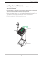
Installing a Passive CPU Heatsink ...................................................................................21
Removing the Heatsink .....................................................................................................22
2.3 Memory Support and Installation .......................................................................................23
Memory Support ................................................................................................................23
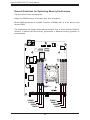
General Guidelines for Optimizing Memory Performance ................................................24
DIMM Installation ..............................................................................................................25
DIMM Removal .................................................................................................................25
2.4 Motherboard Installation .....................................................................................................26
Tools Needed ....................................................................................................................26
Location of Mounting Holes ..............................................................................................26
Installing the Motherboard into the Mounting Tray ...........................................................27
Installing the Motherboard into the Superblade Chassis ..................................................28
2.5 Connectors .........................................................................................................................29
Table of Contents

6
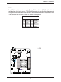
2.8 Jumper Settings .................................................................................................................34
How Jumpers Work ...........................................................................................................34
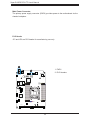
2.9 LED Indicators ....................................................................................................................39
Chapter 3 Troubleshooting
3.1 Troubleshooting Procedures ..............................................................................................40
Before Power On ..............................................................................................................40
No Power ..........................................................................................................................40
No Video ...........................................................................................................................41
System Boot Failure ..........................................................................................................41
Memory Errors ..................................................................................................................41
Losing the System's Setup Conguration .........................................................................42
When the System Becomes Unstable ..............................................................................42
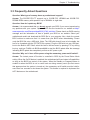
3.2 Technical Support Procedures ...........................................................................................44
3.3 Frequently Asked Questions ..............................................................................................45
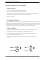
3.4 Battery Removal and Installation .......................................................................................46
Battery Removal ................................................................................................................46
Proper Battery Disposal ....................................................................................................46
Battery Installation .............................................................................................................46
3.5 Returning Merchandise for Service ....................................................................................47
Chapter 4 BIOS
4.1 Introduction .........................................................................................................................48
Starting the Setup Utility ...................................................................................................48
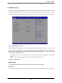
4.2 Main Setup .........................................................................................................................49
4.3 Advanced ............................................................................................................................51
4.4 Event Logs .........................................................................................................................76
4.5 IPMI ....................................................................................................................................78
4.6 Security ...............................................................................................................................82
4.7 Boot ....................................................................................................................................86
4.8 Save & Exit .........................................................................................................................88
Super B11SRE-CPU-TF User's Manual

7
Appendix A BIOS Codes
A.1 BIOS Error POST (Beep) Codes .......................................................................................90
Appendix B Software Installation
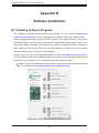
B.1 Installing Software Programs .............................................................................................92
B.2 SuperDoctor
®
5 ...................................................................................................................93
Appendix C Standardized Warning Statements
Appendix D UEFI BIOS Recovery
D.1 Overview .............................................................................................................................97
D.2 Recovering the UEFI BIOS Image .....................................................................................97
D.3 Recovering the BIOS Block with a USB Device ................................................................97
Table of Contents

8
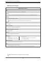
Super B11SRE-CPU-TF User's Manual
Main Parts List (included in the retail box)
Description Part Number Quantity
Supermicro motherboard MBD-B11SRE-CPU-TF 1
Chapter 1
Introduction
Congratulations on purchasing your computer motherboard from an acknowledged leader in
the industry. Supermicro boards are designed with the utmost attention to detail to provide
you with the highest standards in quality and performance.
Please check that the following items have all been included with your motherboard. If
anything listed here is damaged or missing, contact your retailer. The following items are
included in the retail box:
1.1 Checklist
Important Links
For your system to work properly, please follow the links below to download all necessary
drivers/utilities and the user’s manual for your server.
• Supermicro product manuals: http://www.supermicro.com/support/manuals/
• Product drivers and utilities: https://www.supermicro.com/wftp/driver/
• Product safety info: http://www.supermicro.com/about/policies/safety_information.cfm
• If you have any questions, please contact our support team at: [email protected]m
This manual may be periodically updated without notice. Please check the Supermicro website
for possible updates to the manual revision level.

9
Chapter 1: Introduction
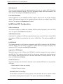
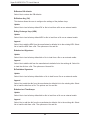
Figure 1-1. Motherboard Image
Note: All graphics shown in this manual were based upon the latest PCB revision
available at the time of publication of the manual. The motherboard you received may
or may not look exactly the same as the graphics shown in this manual.

10
Super B11SRE-CPU-TF User's Manual
SAN CODE
C
A
+
B11SRE-CPU-TF
REV:1.00
MAC CODE
BIOS
LICENSE
IPMI CODE
BAR CODE
PRESS FIT
PRESS FIT
DESIGNED IN USA
I-SATA3
BMC_HB_LED1
JSD1
JBT1
BT1
JRK1
JTPM1
J4
JKVM1
J1
JWD1
JBR1
JPME2
J3
JPG1
JP1
JP2
PWR1
JTAG1
1
1
JSIOM1
DIMMB2
DIMMB1
DIMMA2
DIMMA1
CPU
DIMMC1
DIMMC2
DIMMD2
DIMMD1
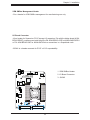
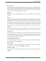
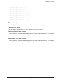
Figure 1-2. Motherboard Layout
(not drawn to scale)
Notes:
• See Chapter 2 for detailed information on jumpers, and I/O ports. Jumpers/components/
LED indicators not indicated are used for internal testing only.
• " " indicates the location of Pin 1.
• Use only the correct type of onboard CMOS battery as specied by the manufacturer. Do
not install the onboard battery upside down to avoid possible explosion.
JTPM1
DIMMA1
DIMMB1
DIMMB2
DIMMA2
JPME2
JBT1
BMC_HB_LED1
JBR1
JWD1
JSD1
BT1
PWR1
JPG1
JP1
JKVM1
JRK1
DIMMD2
DIMMC2
DIMMC1
DIMMD1
JP2
I-SATA3
J4
J3
JSIOM1

11
Chapter 1: Introduction
Quick Reference Table
Jumper Description Default Setting
JBR1 BIOS Recovery Pins 1-2 (Enable)
JBT1 CMOS Clear Open (Normal)
JPG1 VGA Enable/Disable Pins 1-2 (Enabled)
JPME2 Manufacturing Mode Pins 1-2 (Normal)
JWD1 Watch Dog Timer Pins 1-2 (Reset)
Connector Description
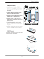
BT1 Onboard Battery
I-SATA3 SATA 3.0 Port
J3 VRM Debug Jumper (Manufacturing Use Only)
J4 PCI-E x16 Slot for I/O Expandability
JKVM1 VGA/USB Module Connector
JP1 PLD Header (Manufacturing Use Only)
JP2 PLD Header (Manufacturing Use Only)
JRK1 Intel RAID Key Header
JSD1 SATA DOM Power Header
JTPM1 Trusted Platform Module (TPM)/Port 80 Header
PWR1 Power Receptacle to Chassis Backplane
LED Description Status
BMC_HB_LED1 BMC Heartbeat Blinking Green: BMC Normal

12
Super B11SRE-CPU-TF User's Manual
Motherboard Features
CPU
• Supports an Intel Xeon W family processor in an LGA2066 socket.
Memory
• Supports up to 512GB LRDIMM/256GB RDIMM DDR4 memory with speeds of up to 2666MHz in eight slots.
DIMM Size
• 4GB, 8GB, 16GB, 32GB, and 64GB
Note 1: Refer to the motherboard product page for the list of supported memory.
Chipset
• Intel C422
Network Controller
• Intel Dual X710 10GbE via Blade Backplane
Baseboard Management Controller
• Aspeed AST2500
Graphics
• Graphics controller via ASpeed AST2500
I/O Devices
• SATA 3.0
• AOM-BPNIO-SCE (connected via J4)
• AOM-BPNIO-SNE (connected via J4)
• One SATA 3.0 port
• 2x 2.5" NVMe + 1x SAS3/SATA3 or 3x SAS3/SATA3
• 3x 2.5" NVMe or 3x SATA3
Peripheral Devices
• Two (2) USB 2.0 ports via JKVM1 header (debug only)
BIOS
• 256Mb SPI AMI BIOS
®
SM Flash UEFI BIOS
• ACPI 6.2, SMBIOS 2.8/3.2, UEFI 2.7 specication, PCI F/W 3.1, Plug and Play (PnP), RTC wake up
Motherboard Features
Note: The table above is continued on the next page.

13
Chapter 1: Introduction
Motherboard Features
Power Management
• Power button override mechanism
• Management Engine (ME)
• Power-on mode for AC recovery
System Health Monitoring
• Onboard voltage monitoring for +1.8V, +3.3V, +3.3V Stdby, +5V, +5V Stdby, +12V, VBAT, HT, Memory
• 6+2 CPU switching phase voltage regulator
• CPU Thermal Trip support
System Management
• Trusted Platform Module (TPM) support
• PECI (Platform Environment Control Interface) 2.0 support
• IPMI 2.0
• Watch Dog, NMI
LED Indicators
• CPU/System Overheat LED
• Power/Suspend State Indicator LED
• Fan Fail LED
• UID/Remote LED
• LAN Activity LED
Dimensions
• 9.36" (W) x 11.61" (L) (237.74 mm x 294.89 mm)
Note 1: The CPU maximum thermal design power (TDP) is subject to chassis and
heatsink cooling restrictions. For proper thermal management, check the chassis and
heatsink specications for proper CPU TDP sizing.
Note 2: For IPMI conguration instructions, please refer to the Embedded IPMI Con-
guration User's Guide available at http://www.supermicro.com/support/manuals/.
Note 3: If you purchase a Supermicro Out of Band (OOB) software license key
(Supermicro P/N: SFT-OOB-LIC), please DO NOT change the IPMI MAC address.
Once the Mac address has been changed, the OOB license key will be invalid.

14
Super B11SRE-CPU-TF User's Manual
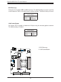
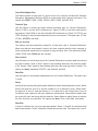
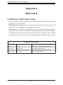
Note: This is a general block diagram and may not exactly represent the features on
your motherboard. See the previous pages for the actual specications of your moth-
erboard.
Figure 1-3.
B11SRE-CPU-TF System Block Diagram
Xeon-W
R4 LGA2066
IMC0
Channel A
1DPC/2666 MHz
IMC1
DIMMA2
DIMMA1
DIMMB1
DIMMB2
Channel B
Channel C
Channel D
DIMMC2
DIMMC1
DIMMD2
DIMMD1
DMI
8.0 GT/s
DMI 3.0 x4
PCH-H
C422
PCIe 3.0 x16
8.0 GT/s
8.0 GT/s
PCIe 3.0 x16
8.0 GT/s
PCIe 3.0 x8
AST2500
50 MHz
480 Mbps
1 x USB 2.0
5 GT/s
PCIe 2.0 x1
ESPI
PEG PEG PEG
Intel X710-BM2
UART
RGB
2 x USB 2.0
480 Mbps
JKVM1
SATA 3.0
SATA
DOM
6.0 Gbps
SPI
32MB BIOS
FLASH
1 x USB 3.0
5.0 Gbps
Intel DCI
Console
Raiser I/O
I/O Board
64MB F/W
Flash
DDR4
512MB
DDR4
SPI
125 MHz
RTL8211FS
RGMII
1Gbps
1000BASE-X
BPN
CONNECTOR
10Gbps
2 x 10GBASE-KR
3 x SATA 3.0
6.0 Gbps
2DPC/2400 MHz
1DPC/2666 MHz
2DPC/2400 MHz
1DPC/2666 MHz
2DPC/2400 MHz
1DPC/2666 MHz
2DPC/2400 MHz
x8/x4/x4
x16
x8/x4

15
Chapter 1: Introduction
1.2 Processor and Chipset Overview
The Supermicro B11SRE-CPU-TF motherboard, using the C422 chipset, supports Intel Xeon
W processors and provides superb performance, efcient power management, all the while
providing a rich feature set based on cutting edge technology to address today's needs in
advanced computing, engineering simulation, automation, etc.
The Intel Xeon W processor and the C422 chipset support the following features:
• Intel Hyper-Threading, Intel VT-D, VT-x
• Intel Turbo Boost Technology
• Intel Rapid Storage Technology
• 64GB DDR4 Load Reduced RDIMM memory support with speeds of up to 2666MHz
• ACPI Power Management
1.3 Special Features
This section describes the health monitoring features of the B11SRE-CPU-TF motherboard.
The motherboard has an onboard System Hardware Monitor chip that supports system health
monitoring.
Recovery from AC Power Loss
The Basic I/O System (BIOS) provides a setting that determines how the system will respond
when AC power is lost and then restored to the system. You can choose for the system to
remain powered off (in which case you must press the power switch to turn it back on), or
for it to automatically return to the power-on state. See the Advanced BIOS Setup section
for this setting. The default setting is Last State.
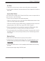
1.4 System Health Monitoring
Onboard Voltage Monitors
The onboard voltage monitor will continuously scan crucial voltage levels. Once a voltage
becomes unstable, it will give a warning or send an error message to the screen. The user
can adjust the voltage thresholds to dene the sensitivity of the voltage monitor. Real time
readings of these voltage levels are all displayed in BIOS.

16
Super B11SRE-CPU-TF User's Manual
Fan Status Monitor with Firmware Control
The system health monitor chip can check the RPM status of a cooling fan. The CPU and
chassis fans are controlled by the BIOS Thermal Management.
Environmental Temperature Control
The thermal control sensor monitors the CPU temperature in real time and will turn on the
thermal control fan whenever the CPU temperature exceeds a user-dened threshold. The
overheat circuitry runs independently from the CPU. Once the thermal sensor detects that
the CPU temperature is too high, it will automatically turn on the thermal fans to prevent the
CPU from overheating. The onboard chassis thermal circuitry can monitor the overall system
temperature and alert the user when the chassis temperature is too high.
Note: To avoid possible system overheating, please provide adequate airow to your
system.
System Resource Alert
This feature is available when used with SuperDoctor 5
®
in the Windows
®
operating system or
in the Linux environment. SuperDoctor 5 is used to notify the user of certain system events.
For example, you can congure SuperDoctor 5 to provide you with warnings when the system
temperature, CPU temperatures, voltages and fan speeds go beyond a predened range.
1.5 ACPI Features
ACPI stands for Advanced Conguration and Power Interface. The ACPI specication denes
a exible and abstract hardware interface that provides a standard way to integrate power
management features throughout a computer system including its hardware, operating
system, and application software. This enables the system to automatically turn on and off
peripherals such as network cards, hard disk drives, and printers.
In addition to enabling operating system-directed power management, ACPI also provides a
generic system event mechanism for Plug and Play and an operating system-independent
interface for conguration control. ACPI leverages the Plug and Play BIOS data structures
while providing a processor architecture-independent implementation that is compatible with
Windows
®
10 operating system.

17
Chapter 2: Installation
Chapter 2
Installation
2.1 Static-Sensitive Devices
Electrostatic Discharge (ESD) can damage electronic com ponents. To avoid damaging
your motherboard and your system, it is important to handle it very carefully. The following
measures are generally sufcient to protect your equipment from ESD.
Precautions
• Use a grounded wrist strap designed to prevent static discharge.
• Touch a grounded metal object before removing the board from the antistatic bag.
• Handle the board by its edges only; do not touch its components, peripheral chips, memory
modules or gold contacts.
• When handling chips or modules, avoid touching their pins.
• Put the motherboard and peripherals back into their antistatic bags when not in use.
• For grounding purposes, make sure that your chassis provides excellent conductivity be-
tween the power supply, the case, the mounting fasteners and the motherboard.
• Use only the correct type of CMOS onboard battery as specied by the manufacturer. Do
not install the CMOS battery upside down, which may result in a possible explosion.
Unpacking
The motherboard is shipped in antistatic packaging to avoid static damage. When unpacking
the motherboard, make sure that the person handling it is static protected.

18
Super B11SRE-CPU-TF User's Manual
2.2 Processor and Heatsink Installation
Warning: When handling the processor package, avoid placing direct pressure on the label
area of the fan.
Important:
• Always connect the power cord last, and always remove it before adding, removing or
changing any hardware components. Make sure that you install the processor into the
CPU socket before you install the CPU heatsink.
• If you buy a CPU separately, make sure that you use an Intel-certied multi-directional
heatsink only.
• Make sure to install the motherboard into the chassis before you install the CPU heatsink.
• When receiving a motherboard without a processor pre-installed, make sure that the plastic
CPU socket cap is in place and none of the socket pins are bent; otherwise, contact your
retailer immediately.
• Refer to the Supermicro website for updates on CPU support.
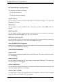
Press down on
load lever labeled
"Open 1st"
1
OPEN 1st
Installing a CPU
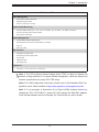
1. There are two load levers on the LGA 2066 socket. To open the socket cover, press and
release the load lever labeled "Open 1st".

19
Chapter 2: Installation
2. Press the second load lever labeled "Close 1st" to release the load plate that covers the
CPU socket from its locking position.
OPEN 1st
1
2
Press down on
load lever
"Close 1st"
Pull lever away from
socket
OPEN 1st
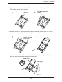
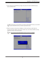
3. With the "Close 1st" lever fully retracted, gently push down on the "Open 1st" lever to
open the load plate. Lift the load plate to open it completely.
OPEN 1st
Gently push down
to pop the load
plate open
2
1
4. Use your thumb and index nger to hold the CPU by its edges. Align the CPU keys,
which are semi-circle cutouts, against the socket keys.
Socket Keys
CPU Keys

20
Super B11SRE-CPU-TF User's Manual
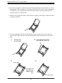
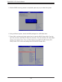
5. Once they are aligned, carefully lower the CPU straight down into the socket. To avoid
damaging the CPU or socket, do not drop the CPU onto the socket, move it horizontally
or vertically, or rub it against the socket pins. Note that you can only install the CPU
inside the socket in one direction.
6. With the CPU inside the socket, inspect the four corners of the CPU to make sure that it
is properly installed.
7. Close the load plate with the CPU inside the socket. Lock the "Close 1st" lever rst,
then lock the "Open 1st" lever second. Gently push the load levers down to the lever
locks.
Push down and lock the
lever labeled "Close 1st"
Gently close
the load plate
1
2
OPEN 1st
OPEN 1st
Lever Lock
Lever Lock
Push down and
lock the lever
labeled "Open
1st"
3
4
OPEN 1st
Page is loading ...
Page is loading ...
Page is loading ...
Page is loading ...
Page is loading ...
Page is loading ...
Page is loading ...
Page is loading ...
Page is loading ...
Page is loading ...
Page is loading ...
Page is loading ...
Page is loading ...
Page is loading ...
Page is loading ...
Page is loading ...
Page is loading ...
Page is loading ...
Page is loading ...
Page is loading ...
Page is loading ...
Page is loading ...
Page is loading ...
Page is loading ...
Page is loading ...
Page is loading ...
Page is loading ...
Page is loading ...
Page is loading ...
Page is loading ...
Page is loading ...
Page is loading ...
Page is loading ...
Page is loading ...
Page is loading ...
Page is loading ...
Page is loading ...
Page is loading ...
Page is loading ...
Page is loading ...
Page is loading ...
Page is loading ...
Page is loading ...
Page is loading ...
Page is loading ...
Page is loading ...
Page is loading ...
Page is loading ...
Page is loading ...
Page is loading ...
Page is loading ...
Page is loading ...
Page is loading ...
Page is loading ...
Page is loading ...
Page is loading ...
Page is loading ...
Page is loading ...
Page is loading ...
Page is loading ...
Page is loading ...
Page is loading ...
Page is loading ...
Page is loading ...
Page is loading ...
Page is loading ...
Page is loading ...
Page is loading ...
Page is loading ...
Page is loading ...
Page is loading ...
Page is loading ...
Page is loading ...
Page is loading ...
Page is loading ...
Page is loading ...
Page is loading ...
Page is loading ...
Page is loading ...
Page is loading ...
Page is loading ...
-
 1
1
-
 2
2
-
 3
3
-
 4
4
-
 5
5
-
 6
6
-
 7
7
-
 8
8
-
 9
9
-
 10
10
-
 11
11
-
 12
12
-
 13
13
-
 14
14
-
 15
15
-
 16
16
-
 17
17
-
 18
18
-
 19
19
-
 20
20
-
 21
21
-
 22
22
-
 23
23
-
 24
24
-
 25
25
-
 26
26
-
 27
27
-
 28
28
-
 29
29
-
 30
30
-
 31
31
-
 32
32
-
 33
33
-
 34
34
-
 35
35
-
 36
36
-
 37
37
-
 38
38
-
 39
39
-
 40
40
-
 41
41
-
 42
42
-
 43
43
-
 44
44
-
 45
45
-
 46
46
-
 47
47
-
 48
48
-
 49
49
-
 50
50
-
 51
51
-
 52
52
-
 53
53
-
 54
54
-
 55
55
-
 56
56
-
 57
57
-
 58
58
-
 59
59
-
 60
60
-
 61
61
-
 62
62
-
 63
63
-
 64
64
-
 65
65
-
 66
66
-
 67
67
-
 68
68
-
 69
69
-
 70
70
-
 71
71
-
 72
72
-
 73
73
-
 74
74
-
 75
75
-
 76
76
-
 77
77
-
 78
78
-
 79
79
-
 80
80
-
 81
81
-
 82
82
-
 83
83
-
 84
84
-
 85
85
-
 86
86
-
 87
87
-
 88
88
-
 89
89
-
 90
90
-
 91
91
-
 92
92
-
 93
93
-
 94
94
-
 95
95
-
 96
96
-
 97
97
-
 98
98
-
 99
99
-
 100
100
-
 101
101


Supermicro B11SRE-CPU-TF User manual
- Category
- Server/workstation motherboards
- Type
- User manual
Ask a question and I''ll find the answer in the document
Finding information in a document is now easier with AI
Related papers
-
Supermicro X11SCE-F User manual
-
Supermicro X11SRM-VF User manual
-
Supermicro X11SPD-F User manual
-
Supermicro X11SDD-18C-F User manual
-
Supermicro X11SRL-F User manual
-
Supermicro X11SRA User manual
-
Supermicro X11SCD-F User manual
-
Supermicro X11SPM-TPF User manual
-
-
Other documents
-
Asus P5G41TM Owner's manual
-
Biostar X570GTA User manual
-
-
SUPER MICRO Computer X9DRG-HF User manual
-
MSI Creator X299 Owner's manual
-
Ross 1000-Series Operating instructions
-
-
Corsair CMX8GX3M2A1333C9 User guide
-
ASRock Rack C422 WS/IPMI User manual
-
Thermalright HR-09 Type 4 User manual