Aeotec Smart Switch 7 User manual

Type
User manual
Smart Switch 7
ZW175
Important safety information.
Please re
ad this and the online guide(s) at
support.aeotec.com/ss7 carefully. Failure to follow the
recommendations set forth by Aeotec Limited may be
dangerous or cause a violation of the law. The manufacturer,
importer, distributor, and / or reseller will not be held
responsible for any loss or damage resulting from not
following any instructions in this guide or in other materials.
Smart Switch 7 is intended for indoor use in dry locations
only. Do not use in damp, moist, and / or wet locations.
Quick start.
The
following will step you through installing Smart Switch 7
and connecting it to your Z-Wave network.
1. Plug Smart Switch 7 into a power outlet; its LED will flash
blue slowly.
2. Add Smart Switch 7 to your Z-Wave network;
a. If your Z-Wave gateway supports SmartStart, Smart
Switch 7 is SmartStart enabled allowing you to
connect it to your Z-Wave gateway by scanning your
switch’s QR Code using your gateway’s app. Once
scanned, Smart Switch 7 will join your Z-Wave
network automatically within 10 minutes. Continue
from step 3.
b. Else, set your Z-Wave gateway into its ‘add device’
mode. Refer to the gateway’s manual if you are
unsure of how to perform this step.
c. Tap Smart Switch 7’s Action Button once, its blue LED
will blink.
d. If your gateway supports the Z-Wave Device Specific
Key (DSK) security protocol, enter the first 5 digits of
your switch’s DSK into your gateway’s interface when
prompted.
3. When Smart Switch 7 successfully joins your Z-Wave
network, its LED will become a solid blue colour for 2
seconds. Should its LED still flash blue, this indicates it
was unable to join your Z-Wave network; repeat the
above steps and please contact us for further support if
needed.
Smart Switch 7 is now a part of your Z-Wave home control
system. You can configure it and its automations via your
Z-Wave system; please refer to your software’s user guide
for precise instructions.
Get help & learn more.
Should you encounter any problem with Smart Switch 7, visit
support.aeotec.com/ss7 or contact our support team via
aeotec.com/contact. You can also learn more about Smart
Switch 7 features, configuration options, and technical
specifications at the link.
Gateway compatibility.
To see if this device is known to be compatible with your
Z-Wave gateway, please refer to
aeotec.com/z-wave-gateways.
Español.
Información importante de seguridad.
Por favor, lea cuidadosamente esta información y el manual en
support.aeotec.com/ss7. No cumplir las recomendaciones establecidas por
Aeotec Limited puede ser peligroso o constituir una violación a la ley. El
fabricante, importador, distribuidor y / o revendedor no será considerado
responsable por ninguna pérdida o daño que resulte de no cumplir
cualquiera de las instrucciones contenidas en este manual o en otros
materiales.
Smart Switch 7 está diseñado para su uso en espacios cerrados y secos. No
utilizar en locaciones con condiciones de humedad y / o en espacios
mojados.
Inicio rápido.
El siguiente manual le guiará en la instalación del Smart Switch 7 y su
conexión a su red Z-Wave.
1. Conecte el Smart Switch 7 a una toma de corriente; su LED parpadeará
en azul lentamente.
2. Agregue Smart Switch 7 a su red Z-Wave;
a. Si su puerta de enlace Z-Wave es compatible con SmartStart, Smart
Switch 7 está habilitado para SmartStart, lo que le permite conectarlo a
su puerta de enlace Z-Wave escaneando el código QR de su
interruptor utilizando la aplicación de su puerta de enlace. Una vez
escaneado, Smart Switch 7 se unirá a su red Z-Wave
automáticamente en 10 minutos. Continuar desde el paso 3.
b. De lo contrario, configure su puerta de enlace Z-Wave en su modo
"agregar dispositivo". Consulte el manual de la puerta de enlace si no
está seguro de cómo realizar este paso.
c. Pulse el botón de acción del Smart Switch 7 una vez, su LED azul
parpadeará.
d. Si su puerta de enlace es compatible con el protocolo de seguridad
de la clave específica del dispositivo (DSK) Z-Wave, ingrese los
primeros 5 dígitos del DSK de su conmutador en la interfaz de su
puerta de enlace cuando se le solicite.
3. Cuando Smart Switch 7 se une con éxito a su red Z-Wave, su LED se
convertirá en un color azul sólido durante 2 segundos. Si su LED aún
parpadea en azul, esto indica que no pudo unirse a su red Z-Wave; repita
los pasos anteriores y póngase en contacto con nosotros para obtener
más ayuda si es necesario.
El Smart Switch 7 ahora es parte de su sistema de control de hogar Z-Wave.
Puede configurar tanto el dispositivo como las automatizaciones a través de
su sistema Z-Wave; por favor, para obtener instrucciones más precisas
revise el manual de usuario del Software.
Français.
Informations importantes concernant la sécurité
Veuillez lire attentivement ce document et le(s) guide(s) à l'adresse
support.aeotec.com/ss7. Le non-respect des recommandations formulées
par Aeotec Limited peut être dangereux ou entraîner une violation de la loi.
Le fabricant, l'importateur, le distributeur et / ou le revendeur ne seront pas
tenus responsables de toute perte ou dommage résultant du non-respect
des instructions contenues dans ce guide ou dans d'autres documents.
Smart Switch 7 est destiné à être utilisé à l'intérieur dans des endroits secs
uniquement. Ne pas utiliser dans des endroits humides, mouillés et / ou
trempés.
Démarrage rapide.
Les étapes suivantes vous guideront dans l'installation de Smart Switch 7 et
sa connexion à votre réseau Z-Wave.
1. Branchez la Smart Switch 7 dans une prise de courant; sa barre LED
clignotera lentement en bleu.
2. Ajoutez la Smart Switch 7 à votre réseau Z-Wave ;
a. Si votre passerelle Z-Wave prend en charge SmartStart, Smart Switch
7 est activé par SmartStart, ce qui vous permet de le connecter à votre
passerelle Z-Wave en scannant le code QR de votre commutateur à
l’aide de son application. Une fois numérisé, Smart Switch 7 rejoindra
automatiquement votre réseau Z-Wave dans les 10 minutes. Continuez
à partir de l'étape 3.
b. Sinon, configurez votre passerelle Z-Wave en mode «Ajout de
périphérique». Reportez-vous au manuel de la passerelle si vous ne
savez pas comment effectuer cette étape.
c. Appuyez une fois sur le bouton d'action du commutateur intelligent 7,
son voyant bleu clignotera.
d. Si votre passerelle prend en charge le protocole de sécurité Z-Wave
Device Specific Key (DSK), entrez les 5 premiers chiffres de la clé
DSK de votre commutateur dans l'interface de votre passerelle lorsque
vous y êtes invité.
3. Lorsque la Smart Switch 7 rejoint avec succès votre réseau Z-Wave, sa
LED devient bleue fixe pendant 2 secondes. Si sa DEL clignote toujours
en bleu, cela signifie qu'il n'a pas pu rejoindre votre réseau Z-Wave ;
répétez les étapes ci-dessus et contactez-nous pour plus d'assistance si
nécessaire.
Deutsch.
Wichtige Sicherheitsinformationen.
Bitte lesen Sie dieses Dokument und die Anleitung(en) unter
support.aeotec.com/ss7 sorgfältig durch. Den festgelegten Empfehlungen
der Aeotec Limited nicht zu folgen, kann gefährlich sein oder gegen ein
Gesetz verstoßen. Der Hersteller, Importeur, Vertreiber und / oder Verkäufer
haftet nicht für den Verlust oder Schaden, der durch die Nichtbeachtung der
Vorschriften in dieser Anleitung oder in anderen Material entsteht.
Smart Switch 7 ist nur für den Innengebrauch bestimmt. Nicht in einer
dunstigen, feuchten oder nassen Umgebung verwenden.
Schnellstart.
Im Folgenden werden Sie Schritt für Schritt durch die Installation und das
Verbinden des Smart Switch 7 mit einem Z-Wave Netzwerk geführt.
1. Schließen Sie den Smart Switch 7 an eine Steckdose an; seine LED blinkt
langsam blau.
2. Hinzufügen des Smart Switch 7 zu Ihrem Z-Wave Netzwerk:
a. Wenn Ihr Z-Wave-Gateway SmartStart unterstützt, ist Smart Switch 7
für SmartStart aktiviert, sodass Sie es mit Ihrem Z-Wave-Gateway
verbinden können, indem Sie den QR-Code Ihres Switches mit der
App Ihres Gateways scannen. Nach dem Scannen wird der Smart
Switch 7 innerhalb von 10 Minuten automatisch mit Ihrem
Z-Wave-Netzwerk verbunden. Fahren Sie mit Schritt 3 fort.
b. Anderenfalls setzen Sie Ihr Z-Wave Gateway in den Modus "Gerät
hinzufügen". Lesen Sie im Handbuch des Gateways nach, wenn Sie
nicht sicher sind, wie dieser Schritt ausgeführt werden soll.
c. Tippen Sie einmal auf die Aktionstaste des Smart Switch 7, die blaue
LED blinkt.
d. Wenn Ihr Gateway das DSK-Protokoll (Device Specific Key) von
Z-Wave unterstützt, geben Sie bei Aufforderung die ersten 5 Ziffern
des DSK Ihres Switches in die Schnittstelle Ihres Gateways ein.
3. Wenn der Smart Switch 7 sich erfolgreich mit Ihrem Z-Wave Netzwerk
verbindet, leuchtet seine LED für 2 Sekunden Blau. Wenn seine LED
immer noch blau blinkt, ist die Verbindung mit Ihrem Z-Wave Netzwerk
nicht zustande gekommen. Führen Sie dann das Hinzufügen des Sensors
erneut durch. Für weitere Unterstützung kontaktieren Sie uns.
Der Smart Switch 7 ist jetzt eine Komponente Ihres Z-Wave Smart Home
Systems. Sie können das Gerät und seine Automatisierungen nun über Ihre
Z-Wave Zentrale konfigurieren. Nehmen Sie dazu bitte das Handbuch Ihrer
Z-Wave Zentrale zur Hand und folgen Sie den Anweisungen für eine
Automatisierung.
RGB LED
Action Button
Botón de acción / Bouton
d'action / Aktionsknopf / Pulsante
di azione / Actieknop /
Åtgärdsknapp / Handlingsknapp
Note:
The label of QR Code and Pin Code are
used for SmartStart Inclusion. The Z-Wave DSK
Code is at bottom of the package. Please do
not remove or damage them.
Pin Code: 35732
Italiano.
Informazioni importanti per la sicurezza.
Si prega di leggere attentamente il presente documento e la guida su
support.aeotec.com/ss7. La mancata osservanza di queste
raccomandazioni indicate da Aeotec Limited può essere pericoloso oppure
violare le normi vigenti. Il produttore, importatore, distributore e / o rivenditore
non saranno considerati responsabili per alcuna perdita o danno derivante
dal mancato rispetto di qualsiasi istruzione contenuta nella presente guida o
in altro materiale.
Smart Switch 7 è destinato esclusivamente a un uso interno in luoghi asciutti.
Non utilizzare in luoghi bagnati o umidi.
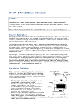
Avvio rapido.
Quanto segue accompagnerà l’utente durante l’installazione di Smart Switch
7 e la relativa connessione alla rete Z-Wave.
1. Inserire il dispositivo Smart Switch 7 in una presa elettrica; la barra LED
lampeggerà brevemente in blu.
2. Aggiungere il dispositivo Smart Switch 7 alla rete Z-Wave.
a. Se il gateway Z-Wave supporta SmartStart, Smart Switch 7 è abilitato
per SmartStart e consente di collegarlo al gateway Z-Wave mediante la
scansione del codice QR dello switch tramite l'app del gateway. Una
volta scansionato, Smart Switch 7 si unirà automaticamente alla rete
Z-Wave entro 10 minuti. Continua dal passaggio 3.
b. Altrimenti, impostare il gateway Z-Wave nella modalità 'Aggiungi
dispositivo'. Fare riferimento al manuale del gateway se non si è sicuri
di come eseguire questo passaggio.
c. Tocca il pulsante Azione di Smart Switch 7 una volta, il suo LED blu
lampeggia.
d. Se il gateway supporta il protocollo di sicurezza della chiave specifica
del dispositivo Z-Wave (DSK), inserire le prime 5 cifre del DSK dello
switch nell'interfaccia del gateway quando richiesto.
3. Una volta che il dispositivo Smart Switch 7 sarà collegato con successo
alla rete Z-Wave, il suo LED si illuminerà di blu per 2 secondi. Nel caso il
LED continui a lampeggiare in blu, il dispositivo non è stato in grado di
collegarsi alla rete di Z-Wave; ripetere i passaggi precedenti e contattare
il nostro servizio clienti in caso sia necessario ulteriore supporto.
A questo punto Smart Switch 7 è parte del sistema di controllo domestico di
Z-Wave. È possibile configurarlo e automatizzarlo attraverso il sistema
Z-Wave; per istruzioni precise, consultare la guida utente del software.
Nederlands.
Belangrijke veiligheidsinformatie.
Lees dit en de handleiding(en) op support.aeotec.com/ss7 zorgvuldig door.
Het niet opvolgen van de aanbevelingen uiteengezet door Aeotec Limited
kan gevaarlijk zijn of een overtreding van de wet veroorzaken. De fabrikant,
importeur, distributeur en / of verkoper kunnen niet aansprakelijk worden
gesteld voor verlies of schade als gevolg van het niet opvolgen van
instructies in deze handleiding of in andere documenten.
Smart Switch 7 is alleen bedoeld voor gebruik binnenshuis, op droge
locaties. Niet gebruiken op vochtige, klamme en / of natte locaties.
Snelstart.
Hieronder volgt een beschrijving van de installatie van Smart Switch 7 en de
verbinding met uw Z-Wave-netwerk.
1. Sluit de Slimme schakelaar 6 aan op een stopcontact; de LED zal
langzaam blauw knipperen.
2. Voeg de Smart Swith 7 toe aan uw Z-Wave netwerk;
a. Als uw Z-Wave gateway SmartStart ondersteunt, is Smart Switch 7
uitgerust met SmartStart, zodat u deze kunt verbinden met uw Z-Wave
gateway door de QR-code van uw switch te scannen met behulp van
de app van uw gateway. Eenmaal gescand, wordt Smart Switch 7
binnen 10 minuten automatisch lid van uw Z-Wave-netwerk. Ga verder
vanaf stap 3.
b. Anders, zet uw Z-Wave-gateway in de modus 'apparaat toevoegen'.
Raadpleeg de handleiding van de gateway als u niet zeker weet hoe u
deze stap moet uitvoeren.
c. Tik eenmaal op de actieknop van Smart Switch 7, de blauwe LED
knippert.
d. Als uw gateway het beveiligingsprotocol van de Z-Wave Device
Specific Key (DSK) ondersteunt, voert u de eerste 5 cijfers van de DSK
van uw switch in de interface van uw gateway in wanneer daarom
wordt gevraagd.
3. Wanneer de Smart Switch 7 succesvol verbinding maakt met uw Z-Wave
netwerk, zal de LED gedurende 2 seconden blauw blijven branden.
Mocht de LED toch blauw blijven knipperen, dan is dit een indicatie dat
het niet is gelukt om verbinding te maken met uw Z-Wave netwerk;
herhaal de bovenstaande stappen en neem contact op met ons voor
verdere hulp indien nodig.
Smart Switch 7 is nu onderdeel van uw Z-Wave thuis beheersysteem. U kunt
het configureren en automatiseren via uw Z-Wave-systeem. Raadpleeg de
gebruikershandleiding van uw software voor instructies.
Svenska.
Viktig säkerhetsinformation.
Vänligen läs denna och guiderna på support.aeotec.com/ss7 noggrant.
Underlåtenhet att följa rekommendationerna från Aeotec Limited kan vara
farligt eller leda till brott mot lagen. Tillverkaren, importören, distributören, och
/ eller återförsäljaren kan inte hållas ansvariga för förlust eller skada som
uppstår från att inte följa instruktionerna i denna handbok eller i andra
material.
Smart Switch 7 är endast avsedd för inomhusbruk på torra platser. Använd
inte i blöta, fuktiga och / eller våta miljöer.
Snabbstart.
Följande kommer att vägleda dig genom installationen av Smart Switch 7 och
anslutning till ditt Z-Wave-nätverk.
1. Anslut Smart Switch 7 till ett vägguttag; dess LED-streck kommer att
blinka blått sakta.
2. Lägg till Smart Switch 7 i ditt Z-Wave-nätverk:
a. Om din Z-Wave-gateway stöder SmartStart, är Smart Switch 7
SmartStart-aktiverad så att du kan ansluta den till din Z-Wave-gateway
genom att skanna din växlar QR-kod med hjälp av din gateways app.
När du har skannat, kommer Smart Switch 7 automatiskt att ansluta till
ditt Z-Wave-nätverk inom 10 minuter. Fortsätt från steg 3.
b. Annars, sätt din Z-Wave-gateway i sitt "add device" -läge. Se
gatewayens manual om du är osäker på hur du utför detta steg.
c. Tryck en gång på Smart Switch 7s Action Button, den blå LED-lampan
blinkar.
d. Om din gateway stöder säkerhetsprotokollet Z-Wave Device Specific
Key (DSK) anger du de första 5 siffrorna i din växels DSK i portens
gränssnitt när du blir ombedd.
3. När Smart Switch 7 lyckas gå med i ditt Z-Wave network kommer dess
LED lysa blått i 2 sekunder. Om dess LED skulle återgå till att blinka blått
har den inte lyckats gå med i ditt Z-Wave-nätverk; repetera stegen ovan
och kontakta oss gärna för support om det behövs.
Smart Switch 7 är nu en del av ditt Z-Wave hemkontrollsystem. Du kan
konfigurera den och dess automationer via ditt Z-Wave-system; Se
programvarans bruksanvisning för exakta instruktioner.
Declaration of Conformity. Aeotec Limited declares that ZW175 is in
compliance with the essential requirements and other relevant provisions of
RED 2014/53/EU, RoHS 2011/65/EU, IEC 62321:2008, EN 50581:2012 and
ErP Directive 2009/125/EC, No 1275/2008 AMENDMENT 801/2013. The full
text of the declaration is available from support.aeotec.com/ss7/doc
Specifications. Z-Wave devices operate between 868.40 & 926.3 MHz
depending on local restrictions. Full information on device specifications and
certifications at support.aeotec.com/ss7/specs
Declaración de conformidad. Aeotec Limited declara que el ZW175 está
en cumplimiento con los requerimientos esenciales y otras provisiones
relevantes de RED 2014/53/EU, RoHS 2011/65/EU, IEC 62321:2008, EN
50581:2012 y las Directrices ErP 2009/125/EC, Nro.1275/2008 ENMIENDA
801/2013. El texto completo de esta declaración está disponible en
support.aeotec.com/ss7/doc
Especificaciones. Los dispositivos Z-Wave operan entre 868,40 y 926,3
MHz dependiendo de las restricciones locales. Puede encontrar la
información completa sobre las especificaciones y certificaciones del
dispositivo en support.aeotec.com/ss7/specs
Déclaration de conformité. Aeotec Limited déclare que le ZW175 est
conforme aux exigences essentielles et autres dispositions pertinentes de
RED 2014/53/EU, RoHS 2011/65/EU, IEC 62321:2008, EN 50581:2012 and
ErP Directive 2009/125/EC, No 1275/2008 AMENDMENT 801/2013. Le texte
intégral de la déclaration est disponible sur support.aeotec.com/ss7/doc
Spécifications. Les appareils Z-Wave fonctionnent entre 868,40 et 926,3
MHz selon les restrictions locales. Informations complètes sur les
spécifications et certifications des appareils sur
support.aeotec.com/ss7/specs
Konformitätserklärung. Aeotec Limited erklärt, dass das ZW175 den
grundlegenden Anforderungen und anderen relevanten Bestimmungen von
RED 2014/53 / EU, RoHS 2011/65 / EU, IEC 62321: 2008, EN 50581: 2012
und ErP-Richtlinie 2009/125 entspricht / EG, Nr. 1275/2008
ÄNDERUNGSANTRAG 801/2013. Der vollständige Wortlaut der Erklärung ist
unter folgender Internetadresse support.aeotec.com/ss7/doc abrufbar.
Spezifikationen. Z-Wave Geräte arbeiten zwischen 868.40 und 926.3 Mhz in
Abhängigkeit von lokalen Beschränkungen. Vollständige Informationen über
Gerätespezifikationen und Zertifizierungen finden Sie auf
support.aeotec.com/ss7/specs
Dichiarazione di conformità. Aeotec Limited dichiara che ZW175 è
conforme ai requisiti fondamentali e altre disposizioni importanti di RED
2014/53/EU, RoHS 2011/65/EU, IEC 62321:2008, EN 50581:2012 e della
Direttiva ErP 2009/125/EC, No 1275/2008 EMENDAMENTO 801/2013. Il testo
complete della dichiarazione è disponibile su support.aeotec.com/ss7/doc
Specifiche tecniche. I dispositivi Z-Wave operano tra 868.40 e 926.3 MHz in
base alle restrizioni locali. Informazioni complete sulle specifiche del
dispositivo e sulle certificazioni su support.aeotec.com/ss7/specs
Conformiteitsverklaring. Aeotec Limited verklaart dat ZW175 voldoet aan
alle essentiële vereisten en andere bepalingen van de Richtlijn
radioapparatuur 2014/53/EU, Richtlijn 2011/65/EU, IEC 62321:2008, EN
50581:2012, en Verordening (EU) nr. 874/2012. De volledige tekst van de
verklaring is beschikbaar vanaf support.aeotec.com/ss7/doc
Specificaties. Z-Wave-apparaten functioneren tussen 868,40 en 926,3 MHz,
afhankelijk van lokale beperkingen. Meer informatie over specificaties en
certificeringen is te vinden op support.aeotec.com/ss7/specs
Deklaration av Överensstämmelse. Aeotec Limited deklarerar att ZW175
överensstämmer med de väsentliga kraven och andra relevanta
bestämmelser i RED 2014/53/EU, RoHS 2011/65/EU, IEC 62321:2008, EN
50581:2012 och ErP Directive 2009/125/EC, No 1275/2008 AMENDMENT
801/2013. Den fullständiga texten för deklarationen är tillgänglig på
support.aeotec.com/ss7/doc
Specifikationer. Z-Wave-enheter kan fungera mellan 868,40 och 926,3 MHz,
beroende på lokala restriktioner. Fullständig information om
enhetsspecifikationer och certifieringar finns på
support.aeotec.com/ss7/specs
AEOTEC Engineering Specification
Smart Switch 7
AEOTEC Engineering Specification
Engineering Specification
Smart Switch 7
Document No.
SPEC-ZW175-C16
Description
This document mainly introduces the new generation AEOTEC Smart Switch. The content mainly
includes its interfaces, accessories, features, specifications, quick start, and software function
definition.
Smart Switch 7 is based on Z-Wave with many advantages.
Elegant appearance, small size, easy to use, friendly operation
Support wireless control with Z-Wave command or manually control with Action Button to
change switch state
Support power metering function, with high measurement accuracy, and more accurate
knowledge of the power consumption of the load
Support over-current, over-load and over-heat protection, which is more secure and reliable
Support scene personalization and is more intelligent
Support Night Light Mode to reduce light pollution
Support S2 Security, which is safer and more reliable
Support SmartStart, making inclusion more convenient
Written By
Date
Reviewed By
Date
Approved By
Date
AEOTEC Engineering Specification
Table of Content
1 INTERFACES & ACCESSORIES .......................................................................................................................................... 1
2 FEATURES & SPECIFICATIONS ......................................................................................................................................... 2
3 PRODUCT QUICK START.................................................................................................................................................. 3
3.1 Important safety information ........................................................................................................................................ 3
3.2 How to install the product ............................................................................................................................................. 3
3.3 How to add the product into Z-Wave network ............................................................................................................... 3
3.3.1 SmartStart Learn Mode ............................................................................................................................................. 3
3.3.2 Classic Inclusion Learn Mode .................................................................................................................................... 3
3.4 How to remove the product from Z-Wave network ....................................................................................................... 4
3.5 How to factory reset ...................................................................................................................................................... 4
4 SOFTWARE FUNCTION DEFINITION ................................................................................................................................ 5
4.1 User Behavior Interaction .............................................................................................................................................. 5
4.2 Supported Command Classes ......................................................................................................................................... 6
4.3 Basic Command Class mapping ..................................................................................................................................... 7
4.4 Z-Wave Plus Info ............................................................................................................................................................ 7
4.5 Manufacturer Specific .................................................................................................................................................... 7
4.6 Version ........................................................................................................................................................................... 8
4.7 Notification .................................................................................................................................................................... 8
4.8 Protection ...................................................................................................................................................................... 8
4.8.1 Protection Supported Report .................................................................................................................................... 8
4.8.2 Protection Set ............................................................................................................................................................ 8
4.9 Association Group Info ................................................................................................................................................. 10
4.10 Configuration ............................................................................................................................................................... 10
AEOTEC Engineering Specification
Page 1
1 INTERFACES & ACCESSORIES
Terminology
Description
Action Button
Used for networking and resetting.
Indicator Light
Used for indicating the current state of the product.
AEOTEC Engineering Specification
Page 2
2 FEATURES & SPECIFICATIONS
Parameter
Value
Product Identifier
ZW175-C16
Dimensions
43.4*43.4*68mm
Weight
56g
Color
White
Shell Material
PC-110N
Shell Surface Treatment
Mirror(upper shell), Bright fine lines(lower shell)
Shell Fire-proof Level
UL94 V-0
Waterproof and Dustproof
Rated IP20 under IEC 60529
Usage
For indoor use
Operating Temperature
32~104°F (0~40°C)
Relative Humidity
8%~80%
Wireless Technology
Z-Wave
Z-Wave Plus
Yes
Z-Wave Module
ZM5101
Z-Wave Version
6.81.03
Z-Wave Library Type
Enhanced 232 Slave
Z-Wave Device Type
On/Off Power Switch
Z-Wave Role Type
Always On Slave
Security Class
Non-Security, S0, S2 Unauthenticated, and S2 Authenticated
Smart Start Compatible
Support
Over The Air (OTA)
Support
Multi Channel Device
No
Association
Support
Factory Reset
Support
Power-down Memory
Support
Z-Wave Antenna Distance
30m (Indoor) /150m (Outdoor)
Plug and Socket Type
Plug Type E/F, Socket Type F
Indicator Light Color
RGB
Buttons and Connectors
Action Button (x1)
Input Voltage
230VAC, 50Hz
Battery Included
No
Battery Required
No
Working Current
7mA±5%(R.M.S) when switch is ON
Standby Current
4mA±5%(R.M.S) when switch is OFF
Maximum Output Current
10A(Resistive load)
Maximum Output Power
2300W
Maximum Standby
Power Consumption
0.8W
Meter Type and Scale
Type=Electric Meter; Scale=kWh(Power Consumption), W(Power), V(Voltage), A(Current)
Power Meter Accuracy
±3W(Less than 300W), ±1%(Over 300W)
Over-Current Protection
Support. Automatically disconnects the load when the current is over 11A.
Over-Load Protection
Support. Automatically disconnects the load when the power is over the threshold value.
Over-Heat Protection
Support. Built-in unrecoverable temperature fuse. Automatically disconnects the load when
the internal temperature exceeds the limit.
Switch Control Method
Wireless control with Z-Wave command or manually control with Action Button.
Night Light Mode
Support. Brightness and color can be customized by user.
Built-in Sensors
No built-in sensors
Safety Certifications
EU: CE
AEOTEC Engineering Specification
Page 3
3 PRODUCT QUICK START
3.1 Important safety information
Please read this Engineering Specification carefully for correct and effective use.
Failure to follow the recommendations set forth by AEOTEC Limited may be dangerous or cause a violation of the law.
The manufacturer, importer, distributor, and/or reseller will not be held responsible for any loss or damage resulting
from not following any instruction in this guide or in other materials.
3.2 How to install the product
3.3 How to add the product into Z-Wave network
This product supports Security 2 Command Class. While a Security S2 enabled Controller is needed in order to fully use
the security feature. This product can be included and operated in any Z-Wave network with other Z-Wave certified
devices from other manufacturers and/or other applications. All non-battery operated nodes within the network will
act as repeaters regardless of vendor to increase reliability of the network.
3.3.1 SmartStart Learn Mode
SmartStart enabled products can be added into a Z-Wave network by scanning the Z-Wave QR Code present on the
product with a controller providing SmartStart inclusion. No further action is required and the SmartStart product will
be added automatically within 10 minutes of being switched on in the network vicinity.
Indicator Light will become flash white light for 1s indicating the product has been powered, and then become flash
blue light indicating SmartStart Learn Mode starts. It will become constantly bright yellow light after being assigned a
NodeID.
If Adding succeeds, it will bright blue light for 2s and become Load Indicator Mode.
If Adding fails, it will bright red light for 2s and turn back to breathing blue light and then start SmartStart Learn Mode
again.
Note:
The label of QR Code on the product and package are used for SmartStart Inclusion. The Z-Wave DSK Code is at bottom
of the package. Please do not remove or damage them.
3.3.2 Classic Inclusion Learn Mode
1. Set your Z-Wave Controller into its 'Add Device' mode in order to add the product into your Z-Wave system. Refer to
the Controller's manual if you are unsure of how to perform this step.
AEOTEC Engineering Specification
Page 4
2. Make sure the product is powered. If not, plug it into a wall socket and power on; its LED will be breathing blue light
all the time.
3. Click Action Button once, it will quickly flash blue light for 30 seconds until it is added into the network. It will
become constantly bright yellow light after being assigned a NodeID.
4. If your Z-Wave Controller supports S2 encryption, enter the first 5 digits of DSK into your Controller's interface if
/when requested. The DSK is printed on its housing.
5. If Adding fails, it will bright red light for 2s and then become breathing blue light; repeat steps 1 to 4. Contact us for
further support if needed.
6. If Adding succeeds, it will bright blue light for 2s and then turn to Load Indicator Mode. Now, this product is a part of
your Z-Wave home control system. You can configure it and its automations via your Z-Wave system; please refer to
your software's user guide for precise instructions.
Note:
If Action Button is clicked again during the Classic Inclusion Learn Mode, the Classic Inclusion Learn Mode will exit. At
the same time, Indicator Light will bright red light for 2s, and then become breathing blue light.
3.4 How to remove the product from Z-Wave network
1. Set your Z-Wave Controller into its 'Remove Device' mode in order to remove the product from your Z-Wave system.
Refer to the Controller's manual if you are unsure of how to perform this step.
2. Make sure the product is powered. If not, plug it into a wall socket and power on.
3. Click Action Button 2 times quickly; it will bright violet light, up to 2s.
4. If Removing fails, it will bright red light for 2s and then turn back to Load Indicator Mode; repeat steps 1 to 3. Contact
us for further support if needed.
5. If Removing succeeds, it will become breathing blue light. Now, it is removed from Z-Wave network successfully.
3.5 How to factory reset
If the primary controller is missing or inoperable, you may need to reset the device to factory settings.
Make sure the product is powered. If not, plug it into a wall socket and power on. To complete the reset process
manually, press and hold the Action Button for at least 15s and then release. The LED indicator will become breathing
blue light, which indicates the reset operation is successful. Otherwise, please try again. Contact us for further support
if needed.
Note:
1. This procedure should only be used when the primary controller is missing or inoperable.
2. Factory Reset will:
(a) Remove the product from Z-Wave network;
(b) Delete the Association setting;
(c) Restore the configuration settings to the default.
AEOTEC Engineering Specification
Page 5
4 SOFTWARE FUNCTION DEFINITION
4.1 User Behavior Interaction
Note: Please refer to Configuration Parameter 0x51 for more details about Load Indicator Mode in the below table.
User behavior
In the Z-Wave network
Power OFF
Cut the power.
Power ON
Supply power:
Indicator Light will become flash white light
for 1s indicating the product has been
powered, and then become Load Indicator
Mode.
Click Action Button once
1.Toggle the switch state:
Indicator Light is closely related to the
configuration of Load Indicator Mode.
2.Exit testing communication quality:
If the product is triggered to testing
communication quality, it will exit when
click the Action Button once, and Indicator
Light will display the color according to the
communication quality, and then turn back
to Load Indicator Mode.
Click Action Button 2 times
quickly
Send Node Info for Removing:
Indicator Light will become violet light for
up to 2s.
If Removing succeeds, it will become
breathing blue light.
If Removing fails, it will bright red light for
2s and then turn back to Load Indicator
Mode.
Click Action Button 3 times
quickly
Disable the Alarm Response:
This function is related to the setting of
Configuration Parameter 10. If Parameter 10
is set to be 0, then when an enable alarm is
received, user can disable the alarm
response by 3x tapping Action Button within
1 second.
Press and hold Action Button
for [1, 2s)
Reserved:
Indicator Light will become off when press,
and become breathing blue light when
release.
AEOTEC Engineering Specification
Page 6
Press and hold Action Button
for [2, 5s)
Change Load Indicator Mode between
Disable Mode and ON/OFF Mode:
Indicator Light will become orange light
when press. And when release, it will change
the Light Indicator Mode from other mode
to Disable Mode, or from Disable Mode to
ON/OFF Mode.
Press and hold Action Button
for [5, 10s)
Test communication quality:
Indicator Light will become cyan light when
press, and quickly flash cyan light when
release, indicating start to test
communication quality between the product
and Node 1.
At the end of the test, Indicator Light will
display the color according to the
communication quality.
If the communication quality is Good, it will
bright green light for 2s.
If the communication quality is General, it
will bright yellow light for 2s.
If the communication quality is Poor, it will
bright red light for 2s.
Press and hold Action Button
for [10, 15s)
Reserved:
Indicator Light will become flash red light
when press, and become Load Indicator
Mode when release.
Press and hold Action Button
for [15, 20s)
Factory Reset(when release)
Indicator Light will become speedup flashing
red light when press, Factory Reset is
performed when release. The product will
send out Device Reset Locally Notification
Report via Lifeline, and it will perform
factory reset no matter the Nodes in the
Lifeline Group receive the Device Reset
Locally Notification from it or not. Indicator
Light will become breathing blue light,
which indicates the reset operation is
successful.
Press and hold Action Button
for [20, )
Factory Reset(forced)
When the time reaches 20s, Factory Reset is
performed no matter Action Button is
pressed or released. The product will send
out Device Reset Locally Notification Report
via Lifeline, and it will perform factory reset
no matter the Nodes in the Lifeline Group
receive the Device Reset Locally Notification
from it or not. Indicator Light will become
breathing blue light, which indicates the
reset operation is successful.
4.2 Supported Command Classes
Note:
When DUT is included on S0 level, MANUFACTURER_SPECIFIC CC is supported non-securely.
When DUT is included on S2 level, MANUFACTURER_SPECIFIC CC is supported securely only.
AEOTEC Engineering Specification
Page 7
Command Class
Version
Not added
Non-secure
added
Securely 0 added
Securely 2 added
Non-secure
Secure
Non-secure
Secure
ZWAVEPLUS_INFO
2
Support
Support
Support
Support
ASSOCIATION
2
Support
Support
Support
Support
ASSOCIATION_GRP_INFO
1
Support
Support
Support
Support
TRANSPORT_SERVICE
2
Support
Support
Support
Support
CONFIGURATION
1
Support
Support
Support
Support
SWITCH_BINARY
1
Support
Support
Support
Support
METER
4
Support
Support
Support
Support
CLOCK
1
Support
Support
Support
Support
SWITCH_COLOR
1
Support
Support
Support
Support
SWITCH_MULTILEVEL
2
Support
Support
Support
Support
NOTIFICATION
4
Support
Support
Support
Support
PROTECTION
2
Support
Support
Support
Support
SCENE_ACTUATOR_CONF 1 Support Support
Support
Support
SCENE_ACTIVATION
1
Support
Support
Support
Support
VERSION 2 Support Support
Support
Support
MANUFACTURER_SPECIFIC 2 Support Support
Support
Support
DEVICE_RESET_LOCALLY 1 Support Support
Support
Support
POWERLEVEL 1 Support Support
Support
Support
SECURITY 1 Support Support
Support
Support
SECURITY_2 1 Support Support
Support
Support
SUPERVISION 1 Support Support
Support
Support
APPLICATION_STATUS 1 Support Support
Support
Support
FIRMWARE_UPDATE_MD
4
Support
Support
Support
Support
4.3 Basic Command Class mapping
Basic Set maps to Binary Switch Set.
Basic Get maps to Binary Switch Get
Basic Report maps to Binary Switch Report.
4.4 Z-Wave Plus Info
Parameter
Value
Z-Wave Plus Version
1
Role Type
5 (ZWAVEPLUS_INFO_REPORT_ROLE_TYPE_SLAVE_ALWAYS_ON)
Node Type
0 (ZWAVEPLUS_INFO_REPORT_NODE_TYPE_ZWAVEPLUS_NODE)
Installer Icon Type
0x0700 (ICON_TYPE_GENERIC_ON_OFF_POWER_SWITCH)
User Icon Type
0x0700 (ICON_TYPE_GENERIC_ON_OFF_POWER_SWITCH)
4.5 Manufacturer Specific
Parameter
Value
Manufacturer ID 1
0x03
Manufacturer ID 2
0x71
Product Type ID 1
0x00(EU)
Product Type ID 2
0x03
Product ID 1
0x00
Product ID 2
0xAF
AEOTEC Engineering Specification
Page 8
4.6 Version
Parameter
Value
Z-Wave Protocol Library Type
0x03
Z-Wave Protocol Version
0x06
Z-Wave Protocol Sub Version
0x04
Firmware 0 Version
ZM5101 Software Version MSB
Firmware 0 Sub Version
ZM5101 Software Version LSB
Hardware Version
0xAF
Number of firmware targets
0x00
4.7 Notification
Notification Type
Notification Events
Description
Power Management
0x08
State idle
0x00
Idle
Over-current detected
0x06
Current is over 11A.
Over-load detected
0x08
Power is over the threshold value.
System
0x09
State idle
0x00
N/A
System hardware failure (manufacturer
proprietary failure code provided)
0x03
Event/State Parameter=0x01:
Built-in unrecoverable temperature fuse
has detected the internal temperature
exceeds the limit and disconnect. It also
means that the product has damaged if
this notification is sent out.
4.8 Protection
4.8.1 Protection Supported Report
Parameter
Value
Local Protection State Byte 1
0x05
Local Protection State Byte 2
0x00
RF Protection State Byte 1
0x03
RF Protection State Byte 2
0x00
Exclusive Control
0x00
Timeout
0x00
4.8.2 Protection Set
Parameter
Value
Function
Local Protection State Byte
0
Unprotected. The device is not protected, and may be operated normally via the
user interface.
2
No operation possible. It is not possible at all to control a device directly via the
user interface.
RF Protection State Byte
0
Unprotected. The device MUST accept and respond to all RF Commands.
1
No RF control - all runtime Commands are ignored by the device. The device
MUST still respond with status on requests.
Note:
(1) Regardless of the state of the product, when over-current or over-load detected, it will automatically TURN OFF
switch and set Local Protection State to be 2 and RF Protection State to be 1, and start red light blinking. Users can’t
manually or RF control the switch state until setting the Protection State to be unprotected through the Gateway or
Controller, even power off will still keep Protection State.
AEOTEC Engineering Specification
Page 9
(2) Different protection trigger
Protection trigger
Activation condition
Result
How to cancel/disable
Local Protection
Protection Set:
Local Protection State = 2
No operation possible. It is not
possible at all to control a device
directly via the user interface.
Protection Set:
Local Protection State = 0
RF Protection
Protection Set:
RF Protection State = 1
No RF control - all runtime
Commands are ignored by the
device.
Protection Set:
RF Protection State = 0
Alarm Report
Receive any alarm enabled by
Alarm Settings (Parameter 9)
(1)Switch will react based on
Alarm Response (Parameter 8),
and Indicator Light will keep
blinking based on Parameter 18.
(2)Local Protection State will NOT
automatically change to be 2.
However, it is not possible at all to
control a device directly via the
user interface until alarm is
disable.
(3)RF Protection State will NOT
automatically change to be 1.
However, Switch will report
Application Rejected Request
when receives any command
which can control the switch state
until alarm is disable.
Based on the setting to
disable alarm (Parameter
10).
Note:
Power off will also disable
the alarm response without
any limitation.
Over-current detected
The current of the load
connected is over 11A.
(1)Blinking red light.
(2)Turn off switch.
(3)Local Protection State will
automatically change to be 2. It is
not possible at all to control a
device directly via the user
interface until users set the Local
Protection State to be
0(unprotected).
(4)RF Protection State will
automatically change to be 1.
Switch will report Application
Rejected Request when receives
any command which can control
the switch state until users set the
RF Protection State to be
0(unprotected).
Protection Set:
Local Protection State = 0
RF Protection State = 0
Over-load detected
The power of the load
connected is over the
threshold value.(Parameter 4)
(1)Blinking red light.
(2)Turn off switch.
(3)Local Protection State will
automatically change to be 2. It is
not possible at all to control a
device directly via the user
interface until users set the Local
Protection State to be
0(unprotected).
(4)RF Protection State will
automatically change to be 1.
Switch will report Application
Rejected Request when receives
any command which can control
the switch state until users set the
RF Protection State to be
0(unprotected).
Protection Set:
Local Protection State = 0
RF Protection State = 0
AEOTEC Engineering Specification
Page 10
4.9 Association Group Info
Root device
ID
Name
Node count
Profile
Function
1
Lifeline
5
General: Lifeline
Device Reset Locally Notification:
Issued when Factory Reset is performed.
Basic Report:
Issued when switch state has changed.
Binary Switch Report:
Issued when switch state has changed.
Color Switch Report:
Issued when a color component level of the Indicator
Light has changed.
Multilevel Switch Report:
Issued when the multilevel switch value of the Indicator
Light has changed.
Notification Report (Type=0x08; Event=0x06):
Issued when over-current detected.
Notification Report (Type=0x08; Event=0x08):
Issued when over-load detected.
Notification Report (Type=0x08; Event=0x00):
Issued when over-current or over-load is release.
Notification Report (Type=0x09; Event=0x03):
Issued when built-in unrecoverable temperature fuse
detected the internal temperature exceeds the limit and
disconnect.
Meter Report:
Issued periodically to report the current Meter reading,
and the sending frequency is related to Configuration
Parameter 0x6F (111).
Issued when the current Power, Power Consumption or
Current is over the threshold value.
2
Retransmit
5
General: NA
Retransmit a Basic Set, Binary Switch Set or Scene
Activation Set to the nodes associated.
4.10 Configuration
Note: R=Read Only, W=Write Only, WR=Write and Read.
Parameter
Description
W/R
Default
Size
0x04(4)
Over-load protection.
Define a threshold power and automatically turn off switch when the load
connected bypasses the maximum allowed power regardless of always on setting.
Value Description
0 Disable over-load protection
1..2415 Threshold power is 1-2145W
Note:
Over-load protection will be active if the load power exceeds the setting and lasts
for more than 30s. If be active, Indicator Light will become red light blinking and
the product will send out Notification Report (Over-load detected), and disable the
function that manually or RF control the switch state until users set Protection State
to be unprotected through the Gateway or Controller. Even power off will still keep
Protection State.
WR
0x096F
(2415W)
2
0x08(8)
Alarm Response.
Enabled by (Alarm Settings), and determines what the switch does in the case an
alarm is triggered.
Value Description
0 Disable, no reaction to alarm settings
1 Switch is ON
2 Switch is OFF
WR
0
1
AEOTEC Engineering Specification
Page 11
3
Switch will turn ON in 5 seconds, and then turn OFF in 5 seconds in a
cycle until user disables the alarm manually
Note:
When receives any alarm enabled by Alarm Settings, Indicator Light will keep
blinking based on Parameter 0x12 (18). It will prohibit user from manually or RF
control the switch state until the alarm is disable.
0x09(9)
Alarm Settings.
Determine if alarms are enabled in Switch, and what Switch will react to which
alarm. The format of the parameter is Bit field (Checkboxes). The parameter MUST
be treated as a bit field where each individual bit can be set or reset. A graphical
configuration tool SHOULD present this parameter as a series of checkboxes.
7 6 5 4 3 2 1 0
Value1 Reserved Home
Security
Access
Control
Water
Alarm
Heart
Alarm
CO2
Alarm
CO
Alarm
Smoke
Alarm
Value2
Reserved
Access
Control
trigger
state
Value1: Supported Notification Type and Notification Event
Value Notification Type Notification Event
1 Smoke Alarm State idle
Smoke detected (location provided)
Smoke detected
2 CO Alarm State idle
Carbon monoxide detected (location provided)
Carbon monoxide detected
4 CO2 Alarm State idle
Carbon dioxide detected (location provided)
Carbon dioxide detected
8 Heart Alarm State idle
Overheat detected (location provided)
Overheat detected
16 Water Alarm State idle
Water leak detected (location provided)
Water leak detected
32 Access Control State idle
Window/door is open
Window/door is closed
64 Home Security State idle
Intrusion (location provided)
Intrusion
Motion detection (location provided)
Motion detection
Value2: Access Control trigger state:
Value Description
0 Alarm will be triggered by open state, and be disable by closed state or
idle state
1 Alarm will be triggered by closed state, and be disable by open state or
idle state
Example:
If the parameter value equals to 8704(0x2200), Alarm Response will active when
receives Carbon monoxide detected or Window/door is open.
If the parameter value equals to 8705(0x2201), Alarm Response will active when
receives Carbon monoxide detected or Window/door is Closed.
WR
0
2
0x0A(10)
Setting to disable alarm.
Determines the method of disabling the alarm of the device.
Value Description
WR
0
2
AEOTEC Engineering Specification
Page 12
0
Can be disabled by 3x tapping Action Button within 1 second
1
Can be disabled when receives a State Idle corresponding to the alarm.
Note: If Access Control is enable, it also can be disabled when receives
the reversal state of window/door.
10..255
Sets the duration of the alarm in seconds(i.e. Customer sets this setting
to 50, the alarm state of the Switch will disable after 50 seconds)
Note:
Power off will also disable the alarm response without any limitation.
0x12(18)
LED blinking frequency.
Value Description
1..9 Set amount of blinks per seconds.
Note:
When receiving the enable Alarm, it will flash according to the blink frequency
configured by this parameter until the Alarm is disable. Brightness level and color
is based on current indicator. If the value of brightness level and color is 0, it will
flash based on last visible color.
WR
2
1
0x13(19)
Start or stop LED blinking.(Write Only)
Value Description
0 Stop blinking.
1..255 Set the duration and start the blinking process.
* This sets the timeframe of blinking in seconds.
* Once the duration ends, the blinking will stop.
Note:
The parameter can be used to test the effect of LED blinking.
W
-
2
0x14(20)
Action in case of power out.
Value Description
0 Last status
1 Switch is on
2 Switch is off
WR
0
1
0x50(80)
Configure what command will be sent via Lifeline when switch state has changed.
Value Description
0 None
1 Basic Report
2 Binary Switch Report
WR
2
1
0x51(81)
Load Indicator Mode setting.
Value Description
0 Disable Mode.
* LED will only illuminate for network removal, press and hold Action
Button.
* No other LED reaction for load status.
* Will allow LED blinking frequency parameter setting to blink the LED.
* Brightness level can NOT be configured via Multilevel Switch CC.
* Color can NOT be configured via Color Switch CC.
* Will report Application Rejected Request when receives Multilevel
Switch CC or Color Switch CC.
1 Night Light Mode.
* During enable time, 100% Red is the default color and can be
changed.
* During disable time, OFF is the default color and can be changed.
* Enable and disable time are defined by Parameter 0x52(82).
* Brightness level can be configured via Multilevel Switch CC.
* Color can be configured via Color Switch CC.
2 ON/OFF Mode.
* ON status, 50% White is the default color and can be changed.
* OFF status, 10% Green is the default color and can be changed.
* Brightness level can be configured via Multilevel Switch CC.
* Color can be configured via Color Switch CC.
Note:
Configuring brightness and color of Indicator Light in different time/status of
different modes will be saved in the current setting mode .
WR
2
1
0x52(82)
Configure the enable and disable time of Night Light Mode
WR
0x12000800
4
AEOTEC Engineering Specification
Page 13
7
6
5
4 3 2
1
0
Value1: Enable Hour
Value2: Enable Minute
Value3: Disable Hour
Value4: Disable Minute
Enable Hour:
Valid value are 0-23 and 127. Value 127 means use last valid setting.
Enable Minute:
Valid value are 0-59 and 255. Value 255 means use last valid setting.
Disable Hour:
Valid value are 0-23 and 255. Value 255 means use last valid setting.
Disable Minute:
Valid value are 0-59 and 255. Value 255 means use last valid setting.
Example:
If you want to set Night Light Mode to be enable at 19:00 at night and disable at
07:30 in the morning, you just need to configure:
Value1=0x13, Value2=0x00, Value3=0x07, Value4=0x1E.
0x5B(91)
Threshold Power (W) for inducing automatic report.
Value Description
0 Disable
1..2300 1-2300W
WR
0
2
0x5C(92)
Threshold Power Consumption (kWh) for inducing automatic report.
Value Description
0 Disable
1..10000 1-10000kWh
WR
0
2
0x5D(93)
Threshold Current (A) for inducing automatic report.
Value Description
0 Disable
1..100 0.1-10A. Unit is 0.1A.
WR
0
1
0x65(101)
Configure which meter reading will be periodically report via Lifeline.
7 6 5 4 3 2 1 0
Reserved
Reserved
Reserved
Reserved Current Voltage Power Power
Consumption
The format of the parameter is Bit field (Checkboxes). The parameter MUST be
treated as a bit field where each individual bit can be set or reset. A graphical
configuration tool SHOULD present this parameter as a series of checkboxes.
Note:
The sending frequency is related to Configuration Parameter 0x6F (111).
WR
0x0000000F
4
0x6F(111)
Configure the sending frequency of Meter Report.
Value Description
0 Disable
600..2592000 600-2592000s. (10minute-30day)
WR
0x00000258
(600s)
4
0xFF(255)
Factory Reset or Initialization (Write Only)
Value Description
1431655765
(0x55555555)
Factory Reset:
Restore the product to factory settings and remove from the
network.
Other Initialization:
Initialize all configuration parameters to default values.
W
-
4
  • Page 1 1
  • Page 2 2
  • Page 3 3
  • Page 4 4
  • Page 5 5
  • Page 6 6
  • Page 7 7
  • Page 8 8
  • Page 9 9
  • Page 10 10
  • Page 11 11
  • Page 12 12
  • Page 13 13
  • Page 14 14
  • Page 15 15
  • Page 16 16
  • Page 17 17
  • Page 18 18

Aeotec Smart Switch 7 User manual

Type
User manual

Ask a question and I''ll find the answer in the document

Finding information in a document is now easier with AI