Page is loading ...

jobAid
1
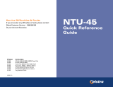
6540 Rear Panel
SHDSL G.703
X.21
V.35/V.36
CONTROL V.28
Nx64K
3
5-80VDC 250mA
NC
+
Express 6500 Series
6540 Front Panel
1. Minor SHDSL port alarms: CRC errors, Loop Attenuation Threshold Alarm, SNR
Margin Threshold Alarm, Segment Anomaly, and any ES, SES, UAS, CVC, and
LOSWS 15-Minute Threshold Alarm
2. Major SHDSL port alarms: LOS, LOSW, or Segment Defect
3. Minor G.703 port alarms: Rx RAI, Frame Slip, CRC-4 errors, LBER, and any ES,
SES, UAS, and CVC 15-Minute Threshold Alarm
4. Major G.703 port alarms: LOS, LOF, LOMF, Rx AIS, or HBER
5. Nx64K port alarms: Clock Slip, Loss of External Clock, FIFO Underflow/Over-
flow, and Inactivity Alarm
G.703 {
z
z
z
Off
Green
Yellow
Red
Port is not active
Active Port with no active alarm
Active Port with a minor alarm
(3)
Active Port with a major alarm
(4)
NX64K {
z
z
Off
Green
Red
Port is not active
Active Port with no active alarm
Active Port with an active alarm condition
(5)
RTS/C {
z
Off
Green
Nx64K port is not active or when active, V.35/
V.36 “Request To Send” or X.21 “Control” line
from the DTE is off
V.35/V.36 “Request To Send” or X.21 “Control”
line from the DTE is on
RLSD/I {
z
Off
Green
Nx64K port is inactive or when active, V.35/
V.36 “Receive Line Signal Detector” and X.21
“Indication” control line from the NTU is off.
V.35/V.36 “Receive Line Signal Detector” or
X.21 “Indication” control line from the NTU
(DCE) is on
LLOOP {
z
z
Off
Yellow
Red
Local Loop is not active
Active Local Loopback on the selected port
Active Local Loop on one or more ports or ser-
vices (when no port is selected)
RLOOP {
z
z
Off
Yellow
Red
Remote Loop is not active
Active Remote Loopback on the selected port
(when determined via established EOC)
Active Remote Loop on one or more ports or ser-
vices (when no port is selected)
BERT {
z
z
z
Off
Green
Yellow
Red
BERT is not active
Active BERT and the test pattern detector is syn-
chronized with no received bit errors
Active BERT and one or more test pattern bit
errors have been received
Active BERT but the test pattern detector is not
synchronized
Label Status Description
DESCRIPTION
The DC Powered 6540 SHDSL 2/Wire/4-Wire NTU (P/N
1230002E1) functions as an interface between the SHDSL network
and the Data Terminal Equipment (DTE).
The 6540 supports applications such as LAN-to-LAN bridging,
Frame Relay circuit, and PABX termination.
The 6540 is designed to be used as either a remote unit to the
ADTRAN Total Access
®
3000 multiservice platform, or as a pair of
units in a point-to-point limited distance campus configuration,
with one 6540 configured to “LT” mode.
FEATURES
The 6540 has the following features:
• Housed in a standalone plastic case
• Provides four front panel recessed pushbuttons and eight
front panel LED indicators
• Provides rear panel SHDSL, G.703 and/or Nx64K ports, and a
local management port
• Provides a rear panel connection for local DC power
• Provides bad splice protection using the ADTRAN proprietary
Runtime TScan™ 2.0 splice protection feature (for more
information on this feature and how to locally manage TScan,
refer to the SHDSL 2-Wire/4-Wire NTU Product Series
Installation and Maintenance Guide, P/N 61230001E1-5)
LED INDICATORS
Label Status Description
SHDSL {
z
z
z
Off
Green
Yellow
Red
Unit is powered off
Port is trained; no active alarms
Port is trained with a minor active alarm
(1)
Port is attempting to or is trained with a major
alarm
(2)
SHDSL
6540 NTU 2-Wire/4-Wire
DC Powered
Product P/N: 1230002E1
Issue Date: September 2011
Document P/N: 61230002E1-22D

2 61230002E1-22D
PUSH BUTTONS
MAINTENANCE
The 6540 does not require routine hardware maintenance for
normal operation. Do not attempt repairs in the field. Repair
services may be obtained by returning the defective unit to
ADTRAN. Refer to the warranty for further information. Field
support for software is provided through upgrade facilities.
Push Button Description
PORT SELECT Press the PORT SELECT button to select the active
port. Selection choices cycle through the following
order: No Port, Nx64k, G.703, SHDSL.
LOCAL LOOP/
ERR INJ
If a port is selected, and a Bit Error Rate Test (BERT) is
not in progress, press the LOCAL LOOP/ERR INJ
button to initiate or terminate a local loop on the
selected port. If a BERT is in progress, press the but-
ton to inject a single bit error.
REMOTE
LOOP
If the SHDSL port is selected, press the REMOTE
LOOP
button to place or remove a remote loop on the
port by sending a EOC request message to the LTU
(or NTU in campus mode). If the Nx64K port or G.703
port (with only one service defined) is selected, press
this button to place or remove a remote loop on the
selected port's single data service by sending respec-
tive inband loop up or loop down patterns to the far
end (in the associated data service timeslots).
BERT If a port is selected and there are no local loops, press
the BERT button to start or stop a BERT on the
selected port.
SPECIFICATIONS
Specifications for the 6540 are as follows:
• Electrical
o Operating Voltage: -48 VDC
o Typical Current and Power Consumption:
120 mA, 5.7 W @ -48 VDC
o Maximum Current Draw: 200 mA @ 35 – 80 VDC
o Maximum Power Consumption: 6.5 watts @ 35 VDC
• Environmental
o Operational Temperature Range: –5°C to +55°C
o Storage Temperature Range: –40°C to +85°C
o Relative Humidity: up to 95%, noncondensing
• Physical
o Height: 2.215 inches (5.63 cm)
o Width: 9.25 inches (23.5 cm)
o Depth: 6.625 inches (16.8 cm)
o Weight: Less than 1 pound (0.45 kg)
INDUSTRY STANDARDS COMPLIANCE
The SHDSL 2-Wire/4-Wire NTU interfaces adhere to these
industry standards, either partially or in full:
• SHDSL: ITU-T G.991.2 (12/03 and 2003 amendments) and
G.994.1 (05/03)
• G.703: ITU-T G.703 (10/98), G.704 (10/98), G.706 (4/91), G.732
(11/88), G.775 (10/98), G.784 (1/94), G.797 (3/96), G.821 (8/
96), G.823 (03/93), and G.826 (2/99)
• Nx64K: ITU-T X.21 (09/92), V.35 (10/84), and V.36 (11/88);
and ISO 2593 (1984), 4903 (1991), and 4902 (1980)
SAFETY AND REGULATORY COMPLIANCE
Refer to the Safety and Regulatory Compliance Notice for this
product (P/N 61230002E1-17) for detailed safety and regulatory
information.
Consultez l'avis sur la sécurité et la conformité à la réglementation
pour ce produit (61230002E1-17) pour obtenir des renseignements
détaillés sur la sécurité et la réglementation.
Ausführliche Sicherheits- und regulatorische Informationen sind
in der Konformitätserklärung zur Sicherheit und Einhaltung von
Normen zu diesem Produkt (61230002E1-17) aufgeführt.

61230002E1-22D 3
MENU TREE
1. Unit Information
Main Menu
2. Provisioning
3. Status
1. NT
2. LT
1. 2-Wire
2. 4-Wire
0. Disabled
1-15. Alarm Threshold
0. Disabled
1-127. Alarm Threshold
0. Disabled
1-900. Seconds
2. Permanent On
3. Sync Mode
1. Permanent Off
1. From DCE, TC (Circuit 114)
2. From DTE, ETC (Circuit 113)
1. Internal Clock
2. Nx64 ETC(113)/X
3. G.703 Rx Clock
0. Disabled
1-900. Seconds
1-65535. Seconds
00h to FFh
1. Unit Options
3. G.703 Options
1. Unit Mode
2. Cross-Connect Map
3. Clock Source
4. Circuit ID
5. Date and Time
6. Restore Factory Defaults
7. Upgrade Firmware
8. Local Management
9. Change Password
1. ES 15-Minute Alarm Threshold
2. SES 15-Minute Alarm Threshold
3. UAS 15-Minute Alarm Threshold
0. Disabled
1-65535. Seconds
4. CVC 15-Minute Alarm Threshold
5. LOSWS 15-Minute Alarm Threshold
6. OS 15-Minute Alarm Threshold
0 to 255 = Delay in ms
2. SHDSL Options
1. ISDN-PRA V3
2. G.704 CRC-4 Multiframing
3. Timeslot Idle Pattern
4. Spare Bits Insertion to Span
5. Spare Bits Pattern to Span
6. Spare Bits Insertion
7. Spare Bits Pattern
8. RAI Generation
9. E-bit Generation
10. ES 15-Minute Alarm Threshold
11. SES 15-Minute Alarm Threshold
12. UAS 15 Minute Alarm Threshold
13. CVC 15-Minute Alarm Threshold
4. Nx64K Options
4. SHDSL Rx Clock
1. Disabled
2. Enabled
* 2-wire mode: 192 kbps to 2.304 Mbps (N x 64 kbps, where N=3 to 36)
4-wire mode: 384 kbps to 4.608 Mbps (N x 64 kbps, where N=even numbers, 6 to 72)
4. Test
5. Performance History
5. G.703 BERT
4. G.703 Local Loopback
7. Nx64k Local Loopback
6. G.703 Services
8. Nx64k Remote Inband Loopback
9. Nx64k BERT
1. SHDSL Port
2. G.703 Port
3. Reset All
7. Terminal Mode
Local Management
Remote Virtual Terminal Management
3. SHDSL BERT
1. Dual Sided
2. Customer Transparent
3. Customer Non-Transparent
4. Network Transparent
5. Network Non-Transparent
1. ALT
2. 2047
3. 2E15-1
4. QRSS
5. Test Options
1. Permanent Off
2. DTE Driven
1. LTU
2. NTU
1. Interface Mode
2. Payload Rate (kbps) *
3. SNR Margin Alarm Threshold (dB)
4. Loop Attenuation Alarm Threshold (dB)
5. Outage Auto-Retrain
6. PM Thresholds
1. Disabled
2. Enabled
0. Disabled
1-900. Seconds
1. Disabled
2. Enabled
1. Disabled
2. Enabled
00h to FFh
1. Disabled
2. Enabled
00h to FFh
1. Disabled
2. Enabled
0. Disabled
1. Interface Type Auto Detection
2. Interface Type Manual Select
3. Inactivity Alarm Delay (Secs)
4. Tx Clock Source
5. Tx Clock Polarity
6. X.21 C Mode
7. X.21 I Mode
8. V.35/V.36 RTS (Circuit 105)
9. V.35/V.36 RTS (Circuit 106)
10. V.35/V.36 RTS to CTS Delay (ms)
11. V.35/V.36 DSR (Circuit 107)
12. V.35/V.36 DTR (Circuit 108/2)
13. CVC 15-Minute Alarm Threshold
1. Disabled
2. Enabled
0. Disabled
1-100. Alarm Threshold
1. Permanent On
2. DTE Driven
1. X.21
2. V.35
3. V.36
1. Normal
2. Inverted
3. Auto
1. Permanent On
2. Sync Mode
1. Permanent On
2. DTE Driven
1. Permanent Off
2. Permanent On
3. RTS Driven
1. Permanent Off
2. Permanent On
1. Permanent On
2. DTE Driven
1. Loopback Types
2. Inband Loopback Options
3. Loopback Timeout (Min)
4. BERT Pattern
5. BERT Pattern Polarity
6. Pushbuttons (All)
7. SHDSL Port Select Pushbuttons
8. V.35/V.36 RL (Circuit 140)
9. V.35/V.36 LL (Circuit 141)
10. V.35/V.36 TI (Circuit 142)
0. Disabled
1-199. Time Out in Minutes
1. In-band Loopback Protocol
2. G.703 Services In-band Pattern Detection
3. Nx64k In-band Pattern Detection
1. Dual Sided
2. Transparent
3. Nontransparent
1. PN127
2. V.54
1. Disabled
2. Enabled
1. Disabled
2. Enabled
1. Normal
2. Inverted
1. Disabled
2. Enabled
1. Permanent Off
2. Test Driven
1. SHDSL Port
2. G.703 Port
3. G.703 Services
4. Nx64K Port
5. Reset All Status
1. SHDSL Local Loopback
2. SHDSL Remote Loopback
2. Remote Inband Loopback
3. BERT
1. Local Loopback
6. TSCAN
1. Restart Bad Splice Detector
2. 24 Hour Counts

For more information, refer to the Installation and Maintenance Guide (P/N 61230001E1-5)
available online at www.adtran.com.
Warranty: ADTRAN will replace or repair this product within the warranty period if it does not
meet its published specifications or fails while in service. Warranty information can be
found online at www.adtran.com/warranty.
©2011 ADTRAN, Inc. All Rights Reserved.
*61230002E1-22D*
CAUTION!
SUBJECT TO ELECTROSTATIC DAMAGE
OR DECREASE IN RELIABILITY
HANDLING PRECAUTIONS REQUIRED
ADTRAN CUSTOMER CARE:
From within the U.S. 1.800.726.8663
From outside the U.S. +1 256.963.8716
PRICING AND AVAILABILITY 1.800.827.0807
/