
Installation RED25
Release
02
07/2015
Technical support
https://hirschmann-support.belden.eu.com
User Manual
Installation
Redundancy Switch
RED25

The naming of copyrighted trademarks in this manual, even when not specially indicated, should
not be taken to mean that these names may be considered as free in the sense of the trademark
and tradename protection law and hence that they may be freely used by anyone.
© 2015 Hirschmann Automation and Control GmbH
Manuals and software are protected by copyright. All rights reserved. The copying, reproduction,
translation, conversion into any electronic medium or machine scannable form is not permitted,
either in whole or in part. An exception is the preparation of a backup copy of the software for
your own use. For devices with embedded software, the end-user license agreement on the
enclosed CD/DVD applies.
The performance features described here are binding only if they have been expressly agreed
when the contract was made. This document was produced by Hirschmann Automation and
Control GmbH according to the best of the company's knowledge. Hirschmann reserves the right
to change the contents of this document without prior notice. Hirschmann can give no guarantee
in respect of the correctness or accuracy of the information in this document.
Hirschmann can accept no responsibility for damages, resulting from the use of the network
components or the associated operating software. In addition, we refer to the conditions of use
specified in the license contract.
You can get the latest version of this manual on the Internet at the Hirschmann product site
(www.hirschmann.com).
Hirschmann Automation and Control GmbH
Stuttgarter Str. 45-51
72654 Neckartenzlingen
Germany
Tel.: +49 1805 141538
Installation RED25 040 068-001-02-0715 -02.07.2015

Installation RED25
Release
02
07/2015
3
Contents
Safety instructions 5
About this manual 11
Key 11
1 Description 12
1.1 General description 12
1.2 Device name and product code 13
1.3 Device views 16
1.4 Power supply 17
1.5 Ethernet ports 17
1.5.1 10/100 Mbit/s twisted pair port 17
1.5.2 100 Mbit/s F/O port (optional) 18
1.6 Display elements 18
1.6.1 Device state 18
1.6.2 Port state 19
1.7 Management interfaces 19
1.7.1 V.24 interface (external management) 19
1.7.2 USB interface 20
1.8 Signal contact 21
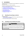
2 Installation 22
2.1 Checking the package contents 22
2.2 Installing and grounding the device 22
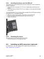
2.2.1 Installing the device onto the DIN rail 23
2.2.2 Grounding the device 23
2.3 Installing an SFP transceiver (optional) 23
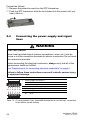
2.4 Connecting the power supply and signal lines 24
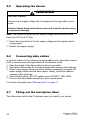
2.5 Operating the device 26
2.6 Connecting data cables 26
2.7 Filling out the inscription label 26
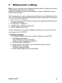
3 Making basic settings 27
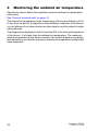
4 Monitoring the ambient air temperature 28


Installation RED25
Release
02
07/2015
5
Safety instructions
General safety instructions
You operate this device with electricity. Improper usage of the device
entails the risk of physical injury or significant property damage. The
proper and safe operation of this device depends on proper handling
during transportation, proper storage and installation, and careful opera-
tion and maintenance procedures.
Before connecting any cable, read this document, and the safety
instructions and warnings.
Operate the device with undamaged components exclusively.
The device is free of any service components. In case of a damaged
or malfunctioning the device, turn off the supply voltage and return the
device to Hirschmann for inspection.
Qualification requirements for personnel
Only allow qualified personnel to work on the device.
Qualified personnel have the following characteristics:
Qualified personnel are properly trained. Training as well as practical
knowledge and experience make up their qualifications. This is the
prerequisite for grounding and labeling circuits, devices, and systems
in accordance with current standards in safety technology.
Qualified personnel are aware of the dangers that exist in their work.
Qualified personnel are familiar with appropriate measures against
these hazards in order to reduce the risk for themselves and others.
Qualified personnel receive training on a regular basis.
Intended usage
Use the product only for the application cases described in the
Hirschmann product information, including this manual.
Operate the product only according to the technical specifications.
See “Technical data” on page 32.
Connect to the product only components suitable for the requirements
of the specific application case.
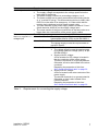
WARNING
UNCONTROLLED MACHINE ACTIONS
To avoid uncontrolled machine actions caused by data loss, configure all
the data transmission devices individually.
Before you start any machine which is controlled via data transmission, be
sure to complete the configuration of all data transmission devices.
Failure to follow these instructions can result in death, serious injury,
or equipment damage.

6
Installation RED25
Release
02
07/2015
National and international safety regulations
Verify that the electrical installation meets local or nationally applicable
safety regulations.
Grounding the device
Grounding the device is by means of a separate ground connection on the
device.
Ground the device before connecting any other cables.
Disconnect the grounding only after disconnecting all other cables.
The overall shield of a connected shielded twisted pair cable is connected
to the ground connector on the front panel as a conductor.
Requirements for connecting electrical conductors
RED25 is a Class III device according to IEC 61010-2-201.
Before connecting the electrical conductors, always verify that all of
the requirements listed are fulfilled:
All of the following requirements are fulfilled:
The electrical wires are voltage-free.
The cables used are permitted for the temperature range of the application case.
Relevant for North America:
The power supply cables are suitable for ambient air temperatures of at least
176 °F (80 °C). The power supply cable wires are made of copper.
Table 1: General requirements for connecting electrical conductors
All of the following requirements are fulfilled:
The voltage connected meets the requirements for a safety extra-low voltage (SELV) as per
IEC/EN 60950-1.
The connected voltage is limited by a current limitation device or a fuse.
Observe the electrical threshold values for the signal contact.
See “General technical data” on page 32.
Table 2: Requirements for connecting the signal contact

Installation RED25
Release
02
07/2015
7
Relevance Requirements
Absolutely relevant All of the following requirements are fulfilled:
The supply voltage corresponds to the voltage specified on the
type plate of the device.
The power supply conforms to overvoltage category I or II.
The power supply has an easily accessible disconnecting device
(e.g., a switch or a plug). This disconnecting device is clearly iden-
tified. So in the case of an emergency, it is clear which discon-
necting device belongs to which power supply cable.
The wire diameter of the power supply cable is at least 0.75 mm²
(North America: AWG18) on the supply voltage input.
The cross-section of the ground conductor is the same size as or
bigger than the cross-section of the power supply cables.
Relevant when the
device is supplied via 1
voltage input
The following requirements are alternatively fulfilled:
Alternative 1 The voltage supply meets the requirements for a
limited power source (LPS) as per EN 60950-1.
Alternative 2 Relevant for North America:
The voltage supply meets the requirements as
per NEC Class 2
Alternative 3 All of the following requirements are fulfilled:
The voltage supply meets the requirements
for a safety extra-low voltage (SELV) as per
IEC/EN 60950-1.
Supply with DC voltage:
A fuse suitable for DC voltage is located in
the plus conductor of the power supply.
The minus conductor is on ground potential.
Otherwise, a fuse is also located in the minus
conductor.
Regarding the properties of this fuse:
See “General technical data” on page 32.
Supply with AC voltage:
A fuse is located in the outer conductor of the
power supply.
The neutral conductor is on ground potential.
Otherwise, a fuse is also located in the
neutral conductor.
Regarding the properties of this fuse:
See “General technical data” on page 32.
Table 3: Requirements for connecting the supply voltage

8
Installation RED25
Release
02
07/2015
Supply voltage
The supply voltage is only connected with the chassis via protective
elements.
Installation site requirements
Verify that there is at least 4 in (10 cm) of space above and below the
device.
Verify that there is at least 0.8 in (2 cm) of space on the right and left
sides of the device.
Install the device in a fire protected enclosure according to
EN 60950-1.
Relevant when the
device is supplied via 2
voltage inputs
The following requirements are alternatively fulfilled:
Alternative 1 The total voltage supply meets the requirements
for a limited power source (LPS) as per EN
60950-1.
Alternative 2 Relevant for North America:
The total voltage supply meets the requirements
as per NEC Class 2.
Alternative 3 All of the following requirements are fulfilled:
The voltage supply meets the requirements
for a safety extra-low voltage (SELV) as per
IEC/EN 60950-1.
Supply with DC voltage:
A fuse suitable for DC voltage is located at
both voltage inputs in the plus conductor of
the power supply.
The minus conductor is on ground potential
at both voltage inputs. Otherwise, a fuse is
also located in the minus conductor.
Regarding the properties of this fuse:
See “General technical data” on page 32.
Supply with AC voltage:
A fuse is located at both voltage inputs in the
outer conductor of the power supply.
The neutral conductor is on ground potential
at both voltage inputs. Otherwise, a fuse is
also located in the neutral conductor.
Regarding the properties of this fuse:
See “General technical data” on page 32.
Relevance Requirements
Table 3: Requirements for connecting the supply voltage

Installation RED25
Release
02
07/2015
9
Housing
Only technicians authorized by the manufacturer are permitted to open
the housing.
Never insert pointed objects (narrow screwdrivers, wires, etc.) into the
device or into the connection terminals for electric conductors. Do not
touch the connection terminals.
Keep the ventilation slits free to ensure good air circulation.
Install the device in the vertical position.
CE marking
The labeled devices comply with the regulations contained in the following
European directive(s):
2011/65/EU (RoHS)
Directive of the European Parliament and of the Council on the restriction
of the use of certain hazardous substances in electrical and electronic
equipment.
2004/108/EC (EMC)
Directive of the European Parliament and the council for standardizing the
regulations of member states with regard to electromagnetic compati-
bility.
In accordance with the above-named EU directive(s), the EU conformity
declaration will be at the disposal of the relevant authorities at the
following address:
Hirschmann Automation and Control GmbH
Stuttgarter Str. 45-51
72654 Neckartenzlingen
Germany
Tel.: +49 1805 141538
The device can be used in the industrial sector.
Interference immunity: EN 61000-6-2
Emitted interference: EN 55022
You find more information on technical and industry standards here:
“Technical data” on page 32
Warning! This is a class A device. This device can cause interference in
living areas, and in this case the operator may be required to take appro-
priate measures.
Note: The assembly guidelines provided in these instructions must be
strictly adhered to in order to observe the EMC threshold values.

10
Installation RED25
Release
02
07/2015
LED or laser components
LED or LASER components according to IEC 60825-1 (2014):
CLASS 1 LASER PRODUCT
CLASS 1 LED PRODUCT
FCC note:
This device complies with part 15 of the FCC rules. Operation is subject
to the following two conditions: (1) this device may not cause harmful
interference; (2) this device must accept any interference received,
including interference that may cause undesired operation.
Appropriate testing has established that this device fulfills the require-
ments of a class A digital device in line with part 15 of the FCC regula-
tions.
These requirements are designed to provide sufficient protection against
interference when the device is being used in a business environment.
The device creates and uses high frequencies and can also radiate these
frequencies. If it is not installed and used in accordance with this oper-
ating manual, it can cause radio transmission interference. The use of this
device in a residential area can also cause interference, and in this case
the user is obliged to cover the costs of removing the interference.
Recycling note
After usage, this device must be disposed of properly as electronic waste,
in accordance with the current disposal regulations of your county, state,
and country.

Installation RED25
Release
02
07/2015
11
About this manual
The “Installation” user manual contains a device description, safety instruc-
tions, a description of the display, and the other information that you need to
install the device.
The following manuals are available as PDF files on the CD/DVD supplied:
Installation user manual
Basic Configuration user manual
Redundancy Configuration user manual
Reference manual for the graphical user interface
Command Line Interface reference manual
User Manual Industry Protocols
The Industrial HiVision network management software provides you with
additional options for smooth configuration and monitoring:
ActiveX control for SCADA integration
Auto-topology discovery
Browser interface
Client/server structure
Event handling
Event log
Simultaneous configuration of multiple devices
Graphical user interface with network layout
SNMP/OPC gateway
Key
The symbols used in this manual have the following meanings:
Listing
Work step
Subheading

12
Installation RED25
Release
02
07/2015
1 Description
1.1 General description
You can choose from between a wide range of variants. You have the option
to set up your device individually based on different criteria:
Types of connectors
Temperature range
Certifications
Redundancy functions
The RED25 devices are designed for the special requirements of industrial
automation. They meet the relevant industry standards, provide very high
operational reliability, even under extreme conditions, and also long-term
reliability and flexibility.
The devices work without a fan.
The device is mounted by latching in place on a DIN rail.
You have the option of choosing various media to connect to the terminal
devices and other network components:
Multimode optical fiber
Singlemode optical fiber
Twisted pair cable
The redundancy concept allows the network to be reconfigured quickly.
There are convenient options for managing the device. Administer your
devices via:
a Web browser
SSH
Telnet
HiDiscovery (Software for putting the device into operation)
network management software (e.g. Industrial HiVision)
a V.24 interface (locally on the device)
The devices provide you with a large range of functions, which the manuals
for the operating software inform you about. You will find these manuals as
PDF files on the enclosed CD/DVD, or you can download them from the
Internet on the Hirschmann product pages (www.hirschmann.com).
The Hirschmann network components help you ensure continuous commu-
nication across all levels of the company.

Installation RED25
Release
02
07/2015
13
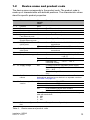
1.2 Device name and product code
The device name corresponds to the product code. The product code is
made up of characteristics with defined positions. The characteristic values
stand for specific product properties.
Item Characteristic Charac-
teristic
value
Description
1 ... 3 Product RED
4 Data rate 2 Fast Ethernet switch
5 Hardware type 5 Extended redundancy
6–
7 ... 8 Number
Fast Ethernet ports
04 4 × Fast Ethernet ports
9 ... 10 Number
Gigabit Ethernet ports
00 0 × Gigabit Ethernet ports
11 ... 13 Configuration of the
uplink ports
2T1 2 × RJ45 socket for 10/100 Mbit/s twisted pair
connections
2Z6 2 × SFP slot for 100 Mbit/s F/O connections
14 ... 15 Configuration of the
other ports
TT 2 × RJ45 socket for 10/100 Mbit/s twisted pair
connections
16 –
17 Temperature range S Standard 0 °C ... +60 °C (+32 °F ...
+140 °F)
T Extended −40 °C ... +60 °C
E Extended with
conformal coating
−40 °C ... +60 °C
18 ... 19 Supply voltage DD 2 voltage inputs for redundant power supply
Rated voltage range DC
12 V ... 48 V
Nominal voltage AC
24 V
20 ... 21 Certificates and decla-
rations
Note: You will find detailed information on the certificates and
declarations applying to your device in a separate overview.
See table 5 on page 14.
22 ... 23 Customer-specific
version
HM Hirschmann Fast MRP
HP Hirschmann PRP
HH Hirschmann HSR
HD From software version 05.0 onward:
Hirschmann DLR
Note: The following redundancy functions are interchange-
able with each other:
HM
HP
HH
24 Software configura-
tion
E Entry (without configuration)
Table 4: Device name and product code

14
Installation RED25
Release
02
07/2015
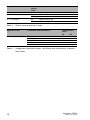
25 ... 26 Software level 2S HiOS Layer 2 Standard
27 ... 31 Software version 04.1. Software-Version 04.1
XX.X. Current software version
32 ... 33 Bug fix 00 Bugfix version 00
XX Current bugfix version
Application case Certificates and declarations Characteristic
value
Y9 Z9
Standard applications CE X X
EN 60950-1 X X
EN 61131-2 X X
FCC X X
UL 61010-1, UL 61010-2-210 X
Table 5: Assignment: application cases, certificates and declarations, character-
istic values
Item Characteristic Charac-
teristic
value
Description
Table 4: Device name and product code

Installation RED25
Release
02
07/2015
15
Item Characteristic Description
RED
1 ... 3 Product
2
4 Data rate Fast Ethernet switch
5
5 Hardware type Extended redundancy
–
6
04
7 ... 8 Number
Fast Ethernet ports
4 × Fast Ethernet ports
00
9 ... 10 Number
Gigabit Ethernet ports
0 × Gigabit Ethernet ports
2T1
11 ... 13 Configuration of the uplink
ports
2 × RJ45 socket for 10/100 Mbit/s twisted pair
connections
TT
14 ... 15 Configuration of the other
ports
2 × RJ45 socket for 10/100 Mbit/s twisted pair
connections
–
16
S
17 Temperature range Standard 0 °C ... +60 °C (+32 °F ...
+140 °F)
DD
18 ... 19 Supply voltage 2 voltage inputs for redundant power supply
Rated voltage range DC
12 V ... 48 V
Nominal voltage AC
24 V
Y9
20 ... 21 Certificates and declara-
tions
Standard applications
CE
EN 60950-1
EN 61131-2
FCC
UL 61010-1, UL 61010-2-210
HM
22 ... 23 Customer-specific version Hirschmann Fast MRP
E
24 Software configuration Entry (without configuration)
2S
25 ... 26 Software level HiOS Layer 2 Standard
04.1.
27 ... 31 Software version Software-Version 04.1
00
32 ... 33 Bug fix Bugfix version 00
Table 6: Sample product code (left column):

16
Installation RED25
Release
02
07/2015
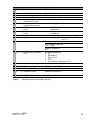
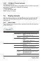
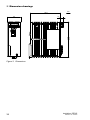
1.3 Device views
1a 6 pin, screwable terminal block for redundant supply voltage and signal contact
1b Terminal block connection
2 On top of the device:
Reset button
(no function in the existing device version)
3 LED display elements for device status
4 USB interface
5 V.24 interface
6 Other ports
2 × RJ45 socket for 10/100 Mbit/s twisted pair connections
7 Uplink ports
alternatively,
depending on
device variant
Characteristic
value
2Z6
2 × SFP slot for 100 Mbit/s F/O connections
Characteristic
value
2T1
2 × RJ45 socket for 10/100 Mbit/s twisted pair
connections
8 Grounding screw
Table 7: Front view:
on the left: Device variants RED25-04002T1TT-.DD....E2S.......
on the right: Device variants RED25-04002Z6TT-.DD....E2S.......
32
1b1a
11
10
6
7
8
9
5
4
7

Installation RED25
Release
02
07/2015
17
1.4 Power supply
A 6-pin, screwable terminal block is available for the redundant supply to the
device.
For further information see “Supply voltage” on page 25.
1.5 Ethernet ports
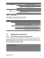
1.5.1 10/100 Mbit/s twisted pair port
The 10/100 Mbit/s twisted pair port offers you the ability to connect network
components according to the IEEE 802.3 10BASE-T/100BASE-TX standard.
This port supports:
Autocrossing (if autonegotiation is activated)
Autonegotiation
Autopolarity
10 Mbit/s half-duplex mode, 10 Mbit/s full duplex mode
100 Mbit/s half-duplex mode, 100 Mbit/s full duplex mode
Delivery state: autonegotiation active
The socket housing is electrically connected with the front panel.
The pin assignment corresponds to MDI-X.
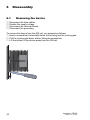
9 Locking gate for removing the device
10 MAC address of device (label)
11 Label area for IP address of device
Pin Function
1 RD+ Receive path
2RD− Receive path
3 TD+ Transmission path
6TD− Transmission path
4,5,7,8 —
Table 8: Pin assignment of the 10/100 Mbit/ twisted pair port, RJ-45 socket, MDI-X
mode
Table 7: Front view:
on the left: Device variants RED25-04002T1TT-.DD....E2S.......
on the right: Device variants RED25-04002Z6TT-.DD....E2S.......
1
2
3
4
5
6
7
8

18
Installation RED25
Release
02
07/2015
1.5.2 100 Mbit/s F/O port (optional)
This port is an SFP slot.
The 100 Mbit/s F/O port offers you the ability to connect network components
according to the IEEE 802.3 100BASE-FX standard.
This port supports:
Full or half duplex mode
Default setting: Full duplex
1.6 Display elements
After the working voltage is set up, the software starts and initializes itself.
Afterwards, the device performs a self-test. During this process, various
LEDs light up.
1.6.1 Device state
These LEDs provide information about conditions which affect the operation
of the whole device.
LED Display Color Activity Meaning
Power Supply voltage — None Supply voltage is too low
Yellow Lights up Device variants with redundant power
supply:
Supply voltage 1 or 2 is on
flashes 4 times
a period
Software update is running. Maintain the
power supply.
Green Lights up Device variants with redundant power
supply:
Supply voltages 1 and 2 are on
Device variants with single power supply:
Supply voltage is on
Status Device Status — None Device is starting and/or is not ready for
operation
Green Lights up Device is ready for operation.
Characteristics can be configured
Red Lights up Device is ready for operation.
Device has detected at least one error in
the monitoring results
Flashes 1 time
a period
The boot parameters used when the
device has been started differ from the
boot parameters saved.
Start the device again.
flashes 4 times
a period
Device has detected a multiple IP address
Status
RM
ACA
Power

Installation RED25
Release
02
07/2015
19
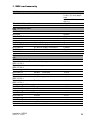
1.6.2 Port state
These LEDs provide port-related information.
The LEDs are directly located on the ports.
1.7 Management interfaces
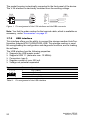
1.7.1 V.24 interface (external management)
The V.24 interface is a serial interface for the local connection of an external
management station (VT100 terminal or PC with terminal emulation). The
interface allows you to set up a data connection to the Command Line Inter-
face (CLI) and to the system monitor.
The V.24 interface is an RJ11 socket.
RM Ring Manager — None No redundancy configured
Green Lights up Redundancy exists
Flashes 1 time
a period
Device is reporting an incorrect configura-
tion of the RM function
Yellow Lights up No redundancy exists
ACA Storage medium
ACA21-
USB/ACA22-USB
— None ACA storage medium not connected
Green Lights up ACA storage medium connected
Flashes 3
times a period
Device writes to/reads from the storage
medium
Yellow Lights up ACA storage medium inoperative
Display Color Activity Meaning
Link status — None Device detects an invalid or missing link
Green Lights up Device detects a valid link
Flashes 1 time a period Port is switched to stand-by
Flashes 3 times a period Port is switched off
Yellow Lights up Device detects a non-supported SFP trans-
ceiver or a non-supported data rate
Flashing Device is transmitting and/or receiving data
Flashes 1 time a period Device detects at least one unauthorized
MAC address (Port Security Violation)
VT 100 terminal settings
Speed 9600 Baud
Data 8 bit
Stopbit 1 bit
Handshake off
Parity none
LED Display Color Activity Meaning

20
Installation RED25
Release
02
07/2015
The socket housing is electrically connected to the front panel of the device.
The V.24 interface is electrically insulated from the working voltage.
Figure 1: Pin assignment of the V.24 interface and the DB9 connector
Note: You find the order number for the terminal cable, which is available as
accessory, under “Accessories” on page 37.
1.7.2 USB interface
This interface offers you the ability to connect the storage medium AutoCon-
figuration AdapterACA21-USB/ACA22-USB. This storage medium is used
for saving/loading the configuration and diagnostic functions, and for loading
the software.
The USB interface has the following properties:
Supports the USB master mode
Supports USB 1.1 (data rate max. 12 MBit/s)
Connectors: type A
Supplies current of max. 500 mA
Voltage not potential-separated
Figure Pin Operation
1VCC (VBus)
2 − Data
3 + Data
4 Ground (GND)
Table 9: Pin assignment of the USB interface
1
1
8
5
6
2
3
5
1
2
3
4
5
6
CTS
n.c.
TX
GND
RX
RTS
RJ11
DB9
RJ11
DB9
1
2
4
3
Page is loading ...
Page is loading ...
Page is loading ...
Page is loading ...
Page is loading ...
Page is loading ...
Page is loading ...
Page is loading ...
Page is loading ...
Page is loading ...
Page is loading ...
Page is loading ...
Page is loading ...
Page is loading ...
Page is loading ...
Page is loading ...
Page is loading ...
Page is loading ...
Page is loading ...
Page is loading ...
-
 1
1
-
 2
2
-
 3
3
-
 4
4
-
 5
5
-
 6
6
-
 7
7
-
 8
8
-
 9
9
-
 10
10
-
 11
11
-
 12
12
-
 13
13
-
 14
14
-
 15
15
-
 16
16
-
 17
17
-
 18
18
-
 19
19
-
 20
20
-
 21
21
-
 22
22
-
 23
23
-
 24
24
-
 25
25
-
 26
26
-
 27
27
-
 28
28
-
 29
29
-
 30
30
-
 31
31
-
 32
32
-
 33
33
-
 34
34
-
 35
35
-
 36
36
-
 37
37
-
 38
38
-
 39
39
-
 40
40


Belden Hirschmann RED25-04002Z6TT Series User manual
- Type
- User manual
- This manual is also suitable for
Ask a question and I''ll find the answer in the document
Finding information in a document is now easier with AI
Related papers
-
Belden Hirschman RSPS20 User manual
-
-
Belden Hirschmann GREYHOUND GPS3-P User manual
-
-
-
-
-
-
-
Belden Hirschmann MACH4002 Series User manual
Other documents
-
Hirschmann RSPL 20/30 User manual
-
-
-
-
Sandberg 504-03 Datasheet
-
-
-
-
-