
Maintenance Manual
PORTEGE X40-K
Series
File Number (960-952)

Maintenance Manual (960-952) 4-2
Replacement Procedures
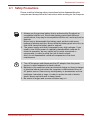
4.1 Safety Precautions
Please read the following safety instructions before disassembling the
computer and always follow the instructions while working on the computer.
1. Always use the genuine battery that is authorized by Dynabook or
compatible with the unit. Since other battery packs have different
specifications, they may be incompatible with the unit, and may burst or
explode.
Never heat or disassemble the battery pack, as that could cause
leakage of alkaline solution. Never throw the battery pack into a fire, as
that could cause the battery pack to explode.
2. The power supply and other components carry high voltages. If you
need to turn on the power of a partially disassembled computer to
check its operation, be very careful not to touch connectors or
components, in order to avoid the risk of electric shock.
Also, do not disassemble individual components in first-level
maintenance.
1. Turn off the power and disconnect the AC adaptor from the power
source, to avoid exposure to electric shock.
2. Batteries in the computer retain an electrical charge, so there is danger
of electrical shock even when the computer is disconnected from an
AC power source. Remove any metal jewelry or accessories such as
necklaces, bracelets or rings, in order to reduce the risk of electric
shock. Never work with wet or damp hands.
3. Be careful of edges and corners as these may cut.

Maintenance Manual (960-952) 4-3
Replacement Procedures
4.2 Before You Begin
Take note of the following points before starting work. Always remove the
AC adaptor and battery pack before commencing any of the procedures.
The procedure for removing the battery pack is described in 4.11 Battery
pack.
1. Do not disassemble the computer unless it is operating abnormally.
2. Use the recommended tools.
3. Ensure that the environment for working on and storing parts does not
contain any of the following.
■Dust or dirt
■Static electricity
■Extremely hot, cold, or humid conditions
4. Perform the diagnostic tests described in Chapter 2 to identify the FRU
that has probably caused the system failure.
5. Do not perform any unnecessary work. Always work in accordance with
the disassembly and re-assembly procedures in this manual.
6. Keep parts removed from the computer in a safe place away from the
computer where they will not be damaged or interfere with your work.
7. Disassembling requires the removal of a large number of screws. Keep
removed screws in a safe place such that you can determine which
screws belong to which part.
8. When re-assembling, ensure that you use the correct screws and fit
parts in the correct position. Screw sizes are noted in the text and
figures.
1. When you change a component, be sure the replacement component
meets the required specifications. Never use foreign parts, to avoid any
risk of damage to the computer.
2. To avoid any risk of short-circuit, fire or other internal damage, never
allow any metal objects such as screws or paper clips to fall into the
unit. Be sure to replace screws with the same size as those removed.
Make sure all screws are securely fastened. Loose screws can cause
short circuits, resulting in heat, smoke or fire.
3. Before lifting out an FRU or other component, make sure all cables to
the component have been disconnected, in order to reduce the risk of
accidental electric shock.
4. If you use AC power, be sure to use the cable that came with the
computer or one recommended by Dynabook.
5. Make sure that all replacement components meet the specifications for
the computer and that all cables and connectors are securely fastened,
in order to avoid the risk of electric shock.
6. Some parts inside the computer, such as the CPU and cooling module,
become very hot during operation. Conduct repair work after they have
cooled. Be careful around the CPU and cooling module to avoid burns.

Maintenance Manual (960-952) 4-4
Replacement Procedures
9. As all parts have sharp edges and corners, take care not to cut yourself.
10. After replacing an FRU, check that the computer and replaced part
operate correctly.
4.3 Disassembly Procedure
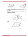
Four main types of cable connector are used.
■Pressure plate connector
■Spring connector
■Back flip connector
■Normal pin connector
For pressure plate connectors, slide the pressure plate holding tags on
both sides of the plastic pressure plate on the connector and pull the cable
out from the connector. When reconnecting the cable to the pressure plate
connector, slide the pressure plate holding tags on both sides of the plastic
pressure plate on the connector and insert the cable into the connector.
Push both tags of the pressure plate such that the cable is fixed in the
correct position. Pull the cable to ensure that it is securely connected.
For spring connectors, lift up the stopper frees the cable and allow it to be
pulled out. To reconnect, hold the stopper in the up position and insert the
cable, then lower the stopper to secure the cable. Pull the cable to ensure
that it is securely connected.
For back flip connectors, lift up the flip plate frees the cable and allow it to
be pulled out. To reconnect, hold the flip plate in the up position and insert
the cable, then lower the flip plate to secure the cable. Pull the cable to
ensure that it is securely connected.
Normal pin connectors are used for all other cables. Simply pull out or push
in these connectors to disconnect or reconnect.
Figure 4-1 Pressure plate connector/Spring connector/Back flip connector
4.4 Assembly Procedures
After the computer has been disassembled and the part that caused the
fault has been repaired or replaced, the computer must be reassembled.

Maintenance Manual (960-952) 4-5
Replacement Procedures
Take note of the following general points when assembling the computer.
■Take your time and follow the instructions carefully. Hurrying the
assembly work will only introduce new problems.
■Check that all cables and connectors are securely connected.
■Before fastening FRUs or other parts in place, ensure that no cables
are caught on screws or the FRU.
■Check that all latches are securely closed.
■Ensure that you have installed all FRUs correctly and do not have any
screws left over. Using an incorrect screw may damage the thread or
screw head and result in the FRU not being securely fastened in place.
After installing FRUs, check that the computer operates correctly.
4.5 Tools and Equipment
For your safety and the safety of the people around you, it is important that
you use Electrostatic Discharge (ESD) equipment. Correctly utilizing of the
equipment increases the percentage of successful repairs and saves on
the cost of damaged or destroyed parts. The following equipment is
required for disassembly and assembly.
■One Philips screwdriver with type 0 bit (for S-THIN HEAD screws)
■One Philips screwdriver with type 1 bit (for screws other than above)
■One flat-blade screwdriver (for removing the CPU)
■Tweezers (for lifting screws)
■ESD mats (lay on work table or floor)
■An ESD wrist strap and heel grounder
■Anti-static carpet or flooring
■Air-ionizers in highly static sensitive areas
■Antenna coaxial cable disconnector
■Special syringe (for applying grease)
4.6 Screw Tightening Torque
When you fasten screws, be sure to follow the torque list below.
■M2 (2mm) 0.167 N•m (1.7 kgf cm)
■M2.5 (2.5mm) 0.294 N•m (3.0 kgf cm)
Overtightening can damage components and screws; undertightening can
result in electrical shorts or other damage if screws or components come
loose.
Dynabook recommends that you use an electric screw driver for quick and
easy operations.

Maintenance Manual (960-952) 4-6
Replacement Procedures
4.7 Grip Color
Some screws have a colored grip area to help you determine the length of
the screw.
[Normal grip]
■Normal length screws: Blue
■Special length screws: Green
■Tight grip screw: Yellow
“Special length screw” means screws whose length is indicated in an
integral number to the first decimal places such as 2.5 mm, 2.6 mm and so
on.
4.8 Screw Notation
To make maintenance of the computer easier, markings of the kinds of the
screws including the types and lengths of the screws are indicated on the
computer body.
Screw type + Screw length (mm)
Screw shape
B: Bind screw
F: Flat head screw
S: Super thin head screw
T: Tapping screw
U: Other screws (Unique screws: pan head, stud, etc.)
To prevent damage to THIN HEAD screws, use type 0 bit philips
screwdriver. Press along the axis of the screwdriver while turning the
screw. This is because the contact area between the screw and driver is
less than for a pan head screw (standard pan-shaped screw head).
Grip area

Maintenance Manual (960-952) 4-7
Replacement Procedures
Example: B6 ... 6mm BIND screw
Screw color/material
B: Black/Nickel
C: Silver/Non-Hexavalent Chromate
U: Other screws (Unique screws: such as stud, etc.)
4.9 Memory media
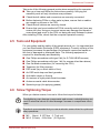
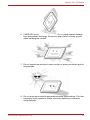
4.9.1 Installing the Memory media
To insert memory media, follow the steps as detailed below and refer to
Figure 4-2.
1. Turn the memory media so that the contacts (metal areas) face down.
2. Insert the memory media into the memory media slot on your computer.
3. Press the memory media gently until it clicks into place.
Figure 4-2 Inserting memory media
4.9.2 Removing the Memory media
To remove memory media, follow the steps as detailed below and refer to
Figure 4-2.
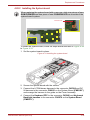
1. Open the Safely Remove Hardware and Eject Media icon on the
Windows Taskbar.
2. Select the memory media that you want to remove.
3. Push the memory media until you hear a click to partially release it.
Insert or remove a Memory media in accordance with any instructions in
each Memory Media manual or the manuals of the computer system you
are using.
1. Memory media slot 2. Memory media
1
2

Maintenance Manual (960-952) 4-8
Replacement Procedures
4. Grasp the media and remove it.
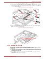
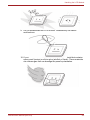
4.10 Cover Assembly and Base Assembly
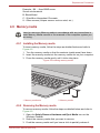
4.10.1 Removing the Cover Assembly and Base Assembly
To remove the Base Assembly, follow the steps below and refer to Figure 4-
3 to Figure 4-5.
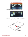
1. Close the display panel and turn the computer face down.
2. Remove the following screws securing the Cover Assembly and the
Base Assembly.
Figure 4-3 Removing the Base Assembly (1)
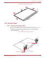
3. Separate the Base Assembly and Cover Assembly while releasing the
latches using the plectrum.
M2.5 x 5.5BT
4
8
2
6
7
9
3
5
9
5
11

Maintenance Manual (960-952) 4-9
Replacement Procedures
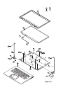
Figure 4-4 Removing the Base Assembly (2)
4. Remove the Base Assembly.
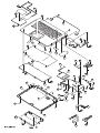
Figure 4-5 Removing the Base Assembly (3)
Cover Assembly
Base Assembly

Maintenance Manual (960-952) 4-10
Replacement Procedures
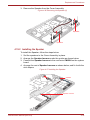
4.10.2 Installing the Base Assembly
To install the Base Assembly, follow the steps below and refer to Figure 4-3
to Figure 4-6.
1. Set the Cover Assembly on the Base Assembly while securing the
latches.
Figure 4-6 Installing the Base Assembly
2. Secure the Cover Assembly and Base Assembly with the screws.
3. Turn the computer, and open the display.
4.11 Battery pack
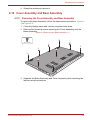
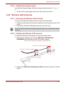
4.11.1 Removing the Battery pack
To remove the battery pack, follow the steps below and refer to Figure 4-7
and Figure 4-8.
1. Disconnect the BATTERY HARNESS from the connector CN8021 on
the SYSTEM board.
2. Remove the following screws and the battery pack.
When securing the Base Assembly, be sure to drive the screws in the
order of the number on Figure 4-3.
Take care not to short circuit the terminals when removing the battery
pack. Similarly, do not drop, knock, scratch, disassemble, twist, or bend
the battery pack.

Maintenance Manual (960-952) 4-11
Replacement Procedures
Figure 4-7 Releasing the battery pack (1)
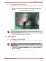
3. Disconnect the BATTERY HARNESS from the connector on the battery
pack.
Figure 4-8 Releasing the battery pack (2)
S2x4CT Battery Harness
CN8021
12
Battery Harness
Battery Pack
1
2
Dispose of the used/removed battery pack in accordance with the laws and
ordinances of your local authority.

Maintenance Manual (960-952) 4-12
Replacement Procedures
4.11.2 Installing the Battery pack
To install the battery pack, follow the steps below and refer to Figure 4-7
and Figure 4-8.
1. Peel off the separator on one side of the battery harness and connect
the BATTERY HARNESS to the connector on the battery pack.
2. Set the battery pack to the COVER ASSY and secure it with the screws.
3. Peel off the separator on the other side of the battery harness and
connect the BATTERY HARNESS to the connector CN8021 on the
SYSTEM board.
4.12 Memory module
4.12.1 Removing the Memory module
To remove the memory module, follow the steps as detailed below:
1. Open the left and right latches outside and remove the memory
module(s).
The lithium ion battery pack may explode if not fitted, operated, handled, or
disposed correctly. Dispose always the used battery pack in accordance
with the laws and ordinances of your local authority.
Use only the batteries approved by Dynabook.
Check the battery’s terminals visually. If they are dirty, wipe them clean
with a dry cloth.
Do not touch the connectors on the memory module or on the computer.
Dust or stains on the connectors may cause memory access problems.
Never press hard or bend the memory module.

Maintenance Manual (960-952) 4-13
Replacement Procedures
Figure 4-9 Removing the memory module(s)
4.12.2 Installing the Memory module
To install a memory module, follow the steps as detailed below:
1. Align the notch of the memory module with that of the memory slot and
gently insert the module into the slot at about a 30 degree angle before
holding it down until the latches on either side snap into place.
Figure 4-10 Seating the memory module
1. Latches 2. Memory module
2
1
1
2
1
After installing the memory module, make sure that the memory module is
secured with the left and right latches.

Maintenance Manual (960-952) 4-14
Replacement Procedures
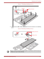
4.13 SSD
4.13.1 Removing the SSD
To remove the SSD, follow the steps below and refer to Figure 4-11.
1. Remove the the following screw and disconnect the SSD from the
connector CN1900 on the SYSTEM board.
Figure 4-11 Removing the SSD
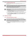
4.13.2 Installing the SSD
To install the SSD, follow the steps below and refer to Figure 4-12.
1. Insert the SSD to the connector CN1900 on the System Board
(FME2SY*) slantwise.
2. Push down the SSD and secure it with the screw.
Take care not to press on the top or bottom of a SSD. Pressure may cause
the data loss or damage to the device.
S2x3.5BT
CN1900
SSD
To avoid damage, always hold the SSD only by its sides.
To prevent the SSD from being distorted when installing the SSD pack into
the computer, do not press the center of the SSD pack. Always hold the
SSD pack by its sides.

Maintenance Manual (960-952) 4-15
Replacement Procedures
Figure 4-12 Installing the SSD
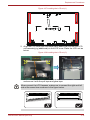
4.14 Smart Card slot
4.14.1 Removing the Smart Card slot
To remove the Smart Card slot unit, follow the steps below and refer to
Figure 4-13 to Figure 4-15.
1. Disconnect the FPC/FFC from the connector CN9600 on the SYSTEM
board and CN9640 on the USB board.
Figure 4-13 Removing the Smart Card slot (1)
2. Peel off the INSU SC from the Smart Card slot.
3. Disconnect the Smart Card FFC from the connector CN2170 on the
system board.
S2x3.5BT
CN1900
SSD
1
2
SUBSUB
1
2
CN9600
CN9640

Maintenance Manual (960-952) 4-16
Replacement Procedures
4. Remove the following screw and peel off the AL TAPE. Then slide and
lift the Smart Card slot unit shown in the following figure to remove the
Smart Card slot.
Figure 4-14 Removing the Smart Card slot (2)
5. Disconnect the Smart Card FFC from the connector on the Smart Card
slot.
Figure 4-15 Removing the Smart Card slot (3)
4.14.2 Installing the Smart Card slot
To install the Smart Card slot, follow the steps below and refer to Figure 4-
13 to Figure 4-17.
1. Connect the Smart Card FFC to the connector on the Smart Card slot.
2. Set the Smart Card slot in place and secure it the with the screw.
3. Connect the Smart Card FFC to the connector CN2170 on the system
board.
4. Stick the AL TAPE in place.
2
3
1
C
FF
F
Card slot FFC
C
tC d l t
C
C
CN2170
Smart Card Slot FFC
S2x2BT
Smart Card slotSmart Card slotSmart Card Slot
2
1

Maintenance Manual (960-952) 4-17
Replacement Procedures
Figure 4-16 Installing the Smart Card slot (1)
5. Stick the INSU SC in place.
Figure 4-17 Installing the Smart Card slot (2)
6. Connect the FPC/FFC to the connector CN9600 on the SYSTEM board
and CN9640 on the USB board.
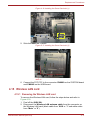
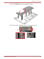
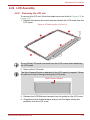
4.15 Wireless LAN card
4.15.1 Removing the Wireless LAN card
To remove the Wireless LAN card, follow the steps below and refer to
Figure 4-18.
1. Peel off the INSU WL.
2. Disconnect the Wireless LAN antenna cable from the connector on
the Wireless LAN card (black cable from “AUX or “1” and white cable
from “Main” or “2”).
INSU SC

Maintenance Manual (960-952) 4-18
Replacement Procedures
3. Release the Wireless LAN antenna cable from the guides on the
Cover Assembly.
4. Remove the screw securing the Wireless LAN card.
5. Disconnect the Wireless LAN card from the connector CN2630 on the
System Board (FME2SY*).
Figure 4-18 Removing the Wireless LAN card
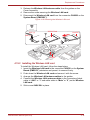
4.15.2 Installing the Wireless LAN card
To install the Wireless LAN card, follow the steps below.
1. Insert the Wireless LAN card to the connector CN2630 on the System
Board (FME2SY*) slantwise and press it to connect firmly.
2. Push down the Wireless LAN card and secure it with the screw.
3. Arrange the Wireless LAN antenna cables to the guides.
4. Connect the Wireless LAN antenna cables to the connectors (black
cable to “AUX” or “1” and white cable to “Main” or “2”) on the Wireless
LAN card.
5. Stick a new INSU WL in place.
S2 x 2.3CT
Insu WLInsu WLInsu WL
AUX (1)
Main (2)
WLAN Card CN2630

Maintenance Manual (960-952) 4-19
Replacement Procedures
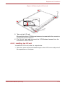
Figure 4-19 Installing the Wireless LAN card
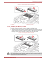
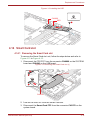
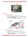
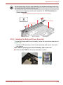
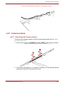
4.16 Fans
4.16.1 Removing the Fans
To remove the Fans, follow the steps below and refer to Figure 4-20.
1. Disconnect the Fan harness from the connector CN3380 and CN3390
on the System Board (FME2SY*).
2. Remove the following screws and the Fans from the Cover Assembly.
Figure 4-20 Removing the Fans
4.16.2 Installing the Fans
To install the Fans, follow the steps below and refer to Figure 4-20.
1. Set the Fans in place on the Cover Assembly and secure them with the
screws.
2. Connect the Fan harness to the connector CN3380 and CN3390 on
the System Board (FME2SY*).
INSU WL
Fan
S2 x 4CT
an
Fan harness
N3390
C
N
Fan Harness
CN3390
N
8
8
CN338
CN3380

Maintenance Manual (960-952) 4-20
Replacement Procedures
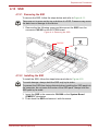
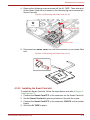
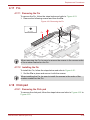
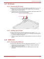
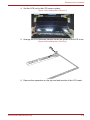
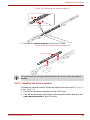
4.17 Fin
4.17.1 Removing the Fin
To remove the Fin, follow the steps below and refer to Figure 4-21.
1. Remove the following screws and then the Fin.
Figure 4-21 Removing the Fin
4.17.2 Installing the Fin
To install the Fin, follow the steps below and refer to Figure 4-21.
1. Set the Fin in place and secure it with the screws.
4.18 Click pad
4.18.1 Removing the Click pad
To remove the click pad, follow the steps below and refer to Figure 4-22 to
Figure 4-23.
Fin
1
2
3
S2 x 2.3CT
When removing the Fin, be sure to remove the screws in the reverse order
of the number marked on the Fin.
When installing the Fin, be sure to install the screws in the order of the
number marked on the Fin.
Page is loading ...
Page is loading ...
Page is loading ...
Page is loading ...
Page is loading ...
Page is loading ...
Page is loading ...
Page is loading ...
Page is loading ...
Page is loading ...
Page is loading ...
Page is loading ...
Page is loading ...
Page is loading ...
Page is loading ...
Page is loading ...
Page is loading ...
Page is loading ...
Page is loading ...
Page is loading ...
Page is loading ...
Page is loading ...
Page is loading ...
Page is loading ...
Page is loading ...
Page is loading ...
-
 1
1
-
 2
2
-
 3
3
-
 4
4
-
 5
5
-
 6
6
-
 7
7
-
 8
8
-
 9
9
-
 10
10
-
 11
11
-
 12
12
-
 13
13
-
 14
14
-
 15
15
-
 16
16
-
 17
17
-
 18
18
-
 19
19
-
 20
20
-
 21
21
-
 22
22
-
 23
23
-
 24
24
-
 25
25
-
 26
26
-
 27
27
-
 28
28
-
 29
29
-
 30
30
-
 31
31
-
 32
32
-
 33
33
-
 34
34
-
 35
35
-
 36
36
-
 37
37
-
 38
38
-
 39
39
-
 40
40
-
 41
41
-
 42
42
-
 43
43
-
 44
44
-
 45
45
-
 46
46


Toshiba X40-K (PMM3A) User guide
- Type
- User guide
- This manual is also suitable for
Ask a question and I''ll find the answer in the document
Finding information in a document is now easier with AI
Related papers
-
Toshiba A50-K (PML30) User guide
-
-
-
-
-
-
-
Toshiba PORT??G?? M750 Maintenance Manual
-
-
Other documents
-
Gateway NV42 Series User manual
-
Panasonic CF-W5LWEZZ1 User manual
-
Acer 581T User manual
-
Dell Precision 7760 Owner's manual
-
Dell Precision 7560 Owner's manual
-
Dell Latitude 7520 Owner's manual
-
Dell Latitude 7420 Owner's manual
-
Dell Latitude 7320 Owner's manual
-
-
 Matsushita CF-W4GWCZZ User manual
