Page is loading ...

www.dragino.com
LM502 22dBm LoRaWAN End Node User Manual 1 / 57
LM502 22dBm SX1262 LoRaWAN module User Manual
Document Version: 1.0
Version
Description
Date
1.0
Release
2019-Sep-10

www.dragino.com
LM502 22dBm LoRaWAN End Node User Manual 2 / 57
1. Introduction .............................................................................................................................. 4
1.1 What is LM502 LoRaWAN End node .......................................................................................... 4
1.2 What is LM502 Demo Board ...................................................................................................... 4
1.3 Specifications .............................................................................................................................. 5
1.4 Features ...................................................................................................................................... 6
1.5 Applications ................................................................................................................................ 6
1.6 Pin Definition .............................................................................................................................. 7
1.7 Software Change log .................................................................................................................. 8
1.8 Hardware Change log ................................................................................................................. 8
1.9 LM502 Demo Kit Introduction .................................................................................................... 9
2. Use the stock firmware ........................................................................................................... 10
2.1 How it works? ........................................................................................................................... 10
2.2 Install virtual CDC serial port for LM502 demo board .............................................................. 10
2.3 Send an AT Command to LM502 .............................................................................................. 10
3. Prepare LoRaWAN network .................................................................................................... 12
4. General Examples ................................................................................................................... 14
4.1 Use AT Command & OTAA to Join LoRaWAN network.............................................................. 14
4.2 Use AT Command & ABP to Join LoRaWAN network ................................................................ 17
4.3 Arduino & OTAA to Join LoRaWAN network ............................................................................. 19
5. Upgrade Firmware to LM502 .................................................................................................. 22
6. Compile Firmware ................................................................................................................... 25
7. Advance Examples .................................................................................................................. 29
7.1 Point to Point transmit LM502 ................................................................................................. 29
7.2 OTAA Join LoRaWAN network without external MCU control .................................................. 32
7.3 Read Digital input & ADC & Interrupt via LoRaWAN Network ................................................. 35
7.3.1 Add digital input pin ....................................................................................................... 35
7.3.2 Add ADC .......................................................................................................................... 37
7.3.3 Add Interrupt pin ............................................................................................................ 39
7.4 Digital Output via LoRaWAN Network ..................................................................................... 43

www.dragino.com
LM502 22dBm LoRaWAN End Node User Manual 3 / 57
7.5 Add DS18B20 Temperature Sensor ........................................................................................... 47
7.6 Add SHT20 I2C device ............................................................................................................... 51
8. FAQ ......................................................................................................................................... 54
8.1 What is the frequency range of LM502? .................................................................................. 54
8.2 How to change the LoRa Frequency Bands/Region? ................................................................ 54
9. Order Info ............................................................................................................................... 55
10. Packing Info ............................................................................................................................ 55
11. Support ................................................................................................................................... 56
12. Reference ................................................................................................................................ 57

www.dragino.com
LM502 22dBm LoRaWAN End Node User Manual 4 / 57
1. Introduction
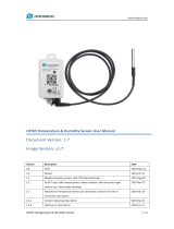
1.1 What is LM502 LoRaWAN End node
The LM502 is a general LoRa Wireless Communication module, with integrated LoRa Radio
Transceiver, SX1262 LoRa Modem and a 32-Bit RISC MCU CY8C4147AXI-S445 from Cypress. The
MCU uses ARM Cortex M0+, with 48MHz operation frequency. The LoRa Radio Transceiver has
continuous frequency coverage from 150MHz to 960MHz. The LoRa Modem supports LoRa
modulation for LPWAN use cases and (G)FSK modulation for legacy use cases.
LM502 use the newest LoRa Modem SX1262 which provide high transmit power for ultra long
range, ultra low power communication for LPWAN application.
LM502 can achieve a high sensitivity of over -140dBm and the maximum transmit power is
higher than +21dBm. This makes it suitable to be used in long range LPWAN and have high
efficiency.
LM502 is provided with ready to use LoRaWAN Modem software. Developers only need to use AT
Commands to control the module so to join the LoRaWAN network.
The LM502 also includes programmable and reconfigurable analog and digital blocks with flexible
automatic routing. Developer can use the rich I/Os to connect to their sensors and provide a low
cost / low power consumption / small size LoRaWAN End Node solution.
1.2 What is LM502 Demo Board
The LM502 demo board is a breakout board for LM502. It helps developers to rapidly evaluate
the features and performances of LM502 and help to develop the software of LM502.
The LM502 demo board is 3.3v I/O base module. It can be powered by micro USB port or DC port.

www.dragino.com
LM502 22dBm LoRaWAN End Node User Manual 5 / 57
The LM502 has a built-in STM32 chip with pre-load DAP-LINK firmware. Use can use the micro
USB port to flash new firmware to LM502 or connect to the UART interface of LM502 by
DAP-LINK.
1.3 Specifications
Micro Controller:
Cypress CY8C4147AXI-S445 MCU
ARM Cortex M0+
Flash:128KB
RAM:16KB
Clock Speed: 48Mhz
Absolute Maximum Ratings (For LM502):
VCC: -0.3 ~ 3.9v
I/O pins: -0.3v ~ 3.9v
RF Input Power: +10dBm
Common DC Characteristics (For LM502):
Supply Voltage: 1.8v ~ 3.7v
Operating Temperature: -40 ~ 85°C
Deep sleep power: 3.4 uA
TX: 112mA @22dBm
I/O pins: Input High: > 0.7x VCC, Input Low: <0.3 x VCC
LoRa Spec:
Frequency Range,
Band 1 (HF): 862 ~ 1020 Mhz
or
Band 2 (LF): 410 ~ 528 Mhz
LoRa Chip: sx1262
170 dB maximum link budget
Max +22 dBm - 100 mW constant RF output
Low RX current of 4.6 mA
Programmable bit rate up to 62.5 kbps LoRa.
High sensitivity: down to -148 dBm
Built-in bit synchronizer for clock recovery
Low RX current of 10.3 mA, 200 nA register retention.
Automatic Channel Activity Detection (CAD) with ultra-fast AFC
High Stability TCXO oscillator
LoRaWAN 1.0.2 Specification

www.dragino.com
LM502 22dBm LoRaWAN End Node User Manual 6 / 57
1.4 Features
Small footprint: 20 mm x 27.5 mm x 2.5 mm.
48-MHz ARM Cortex-M0+ CPU
LoRa Radio and LoRa Modem via SX1262
8-Channel DMA engine.
Low power consumption
Embedded 12-bit 1Msps SAR ADC
SPI, 1xI2C, 2xUART, 1xSWD
3xADC, 1xCOMP.
Baud rate configurable
LoRa™ Modem
Preamble detection
FSK, GFSK, MSK and GMSK modulation
Open source hardware / software
Available Band:433/868/915/920 Mhz
External Antenna via I-Pex connector
ANT on SMD pad
1.5 Applications
Wireless Alarm and Security Systems
Home and Building Automation
Automated Meter Reading
Industrial Monitoring and Control
Long range Irrigation Systems,etc.
Smart Factory

www.dragino.com
LM502 22dBm LoRaWAN End Node User Manual 7 / 57
1.6 Pin Definition
Pin Mapping:
Pin No.
Signal
Direction
Function
Remark
1
VCC(2.9V)
OUTPUT
VCC
Directly connect to main power
for board
2
PA0
In/Out
Directly from STM32 chip
Used as ADC in LSN50 image
3
PA1
In/Out
Directly from STM32 chip
4
PA2
In/Out
Directly from STM32 chip, 10k pull
up to VCC
Used as UART_TXD in LSN50
image
5
PA3
In/Out
Directly from STM32 chip, 10k pull
up to VCC
Used as UART_RXD in LSN50
image
6
PB6
In/Out
Directly from STM32 chip, 10k pull
up to VCC
7
PB7
In/Out
Directly from STM32 chip, 10k pull
up to VCC
8
PB3
In/Out
Directly from STM32 chip, 10k pull
up to VCC

www.dragino.com
LM502 22dBm LoRaWAN End Node User Manual 8 / 57
9
PB4
In/Out
Directly from STM32 chip
10
PA9
In/Out
Directly from STM32 chip, 10k pull
up to VCC
11
PA10
In/Out
Directly from STM32 chip, 10k pull
up to VCC
12
GND
Ground
13
VCC(2.9V)
OUTPUT
VCC
Directly connect to main power
for board
14
Jumper
Power on/off jumper
15
PA4
In/Out
Directly from STM32 chip
16
NRST
In
Reset MCU
17
PA12
In/Out
Directly from STM32 chip
18
PA11
In/Out
Directly from STM32 chip
19
PA14
In/Out
Directly from STM32 chip
20
PB13
In/Out
Directly from STM32 chip
21
PB12
In/Out
Directly from STM32 chip
22
PB15
In/Out
Directly from STM32 chip
23
PB14
In/Out
Directly from STM32 chip
24
PA13
In/Out
Directly from STM32 chip
25
PA8
In/Out
Directly from STM32 chip
Default use to turn on/off LED1
in LSN50 image
26
GND
Ground
27
+5V
Out
5v output power
Controlled by PB5(Low to
Enable, High to Disable)
28
LED1
Controlled by PA8
Blink on transmit
29
BOOT
MODE
Configure device in working mode
or ISP program mode
30
NRST
In
Reset MCU
1.7 Software Change log
This section is for the pre-load software in LM502
1.8 Hardware Change log
LM502 v1.0:

www.dragino.com
LM502 22dBm LoRaWAN End Node User Manual 9 / 57
Release
1.9 LM502 Demo Kit Introduction
The LM502 demo board is a breakout board with LM502 pre-load. The demo board provides a
rapid way to user to evaluate the feature of LM502. The demo board can be powered by 12v DC
or USB port. The USB port of LM502 demo kit will be shown as one program port and one CDC
port in computer, the program port is for flash firmware and CDC port is for serial access to
LM502.

www.dragino.com
LM502 22dBm LoRaWAN End Node User Manual 10 / 57
2. Use the stock firmware
2.1 How it works?
LM502 is shipped with pre-load LoRa Modem software. User can use AT-Command to configure
the module to join the LoRaWAN network.
The AT Command User Manual is here: LM502 AT Command User Manual.
Below are some examples for how to use the AT commands. We test it with the LM502 demo
board.
2.2 Install virtual CDC serial port for LM502 demo board
The LM502 demo board has a built-in DAP-Link interface. User can connect the LM502 UART
interface via USB cable and this DAP-Link interface. User need to install the CDC driver from this
link: http://www.dragino.com/downloads/index.php?dir=LM502/drivers/&file=CMSIS_DAP.inf
2.3 Send an AT Command to LM502
If the DAP CDC install correctly, user should see below screen shot:

www.dragino.com
LM502 22dBm LoRaWAN End Node User Manual 11 / 57
Configure Putty for serial access.
Baud Rate: 115200.
And after access, user can see the output from LM502:

www.dragino.com
LM502 22dBm LoRaWAN End Node User Manual 12 / 57
3. Prepare LoRaWAN network
Most examples used below are based on LoRaWAN protocol. Before doing the testing, we need
to set up a device in LoRaWAN server for LM502.
This section is an example for how to set up a LoRaWAN device in the TTN LoRaWAN Network.
Below is the network structure, we use LG308 as LoRaWAN gateway here.
The LG308 is already set to connect to TTN network . Below is the set up photo for LG308. It
generates a LoRaWAN network in our office and our industrial area.
So what we need now is only add the device to the TTN, with the OTAA Keys from LM502
Step 1: Create a device in TTN with the OTAA keys from LM502.
Each LM502 is shipped with a sticker with the worldwide unique device EUI as below:

www.dragino.com
LM502 22dBm LoRaWAN End Node User Manual 13 / 57
User can enter this key in their LoRaWAN Server portal. Below is TTN screen shot:
Add APP EUI in the application
Add APP KEY and DEV EUI
After above settings, we have an OTAA device for LM502 in TTN.

www.dragino.com
LM502 22dBm LoRaWAN End Node User Manual 14 / 57
4. General Examples
4.1 Use AT Command & OTAA to Join LoRaWAN network
This shipped LM502 has a pre-installed the firmware which support LoRaWAN 1.0.3 protocol.
Developer can use their familiar micro controller as the main MCU and use the LM502 as
LoRaWAN module. The external mcu control LM502 via AT Commands for LoRaWAN transmission.
System structure is as below figure.
In this example, we use Computer to simulate the micro control to send AT Commands for
LoRaWAN communication.
Test set up:
LoRaWAN Network. (How to Prepare LoRaWAN Network?)
LM502-Demo-Board with AT Command works in PC (How to use AT Command?). Photo is as
below

www.dragino.com
LM502 22dBm LoRaWAN End Node User Manual 15 / 57
AT Commands:
AT+CRESTORE //Initiate LM502 module.
AT+CJOIN=1,1,10,8 // Enable OTAA Join to LoRaWAN network, join periodically 10s. max retry
8.If module is reboot, this command need to run again to join network,
AT+DTRX=0,0,10,0123456789 // Send a string 0123456789
Serial Output in LM502 console:


www.dragino.com
LM502 22dBm LoRaWAN End Node User Manual 17 / 57
4.2 Use AT Command & ABP to Join LoRaWAN network
The set up for this example is the same as the OTAA example as above. The difference is that
there is no OTAA join. The LM502 will set uplink directly.
Test set up:
LoRaWAN Network. (How to Prepare LoRaWAN Network?)
LM502-Demo-Board with AT Command works in PC (How to use AT Command?). Photo is as
below
AT Commands:
------------------------------------------------------
AT+CRESTORE // Initiate LM502 module.
AT+CJOINMODE=1 //Set to ABP join, (If LM502 is reboot, user need to run these command
again)
AT+DEVADDR=xxxxxxxx // xxxxxxxx is the Dev Addr from the TTN page.
AT+DTRX=0,0,10,0123456789 // Test command, send “0123456789” to LoRaWAN server.
------------------------------------------------------


www.dragino.com
LM502 22dBm LoRaWAN End Node User Manual 19 / 57
4.3 Arduino & OTAA to Join LoRaWAN network
This example is basically similar with the example of AT Command OTAA example. But we use
Arduino here (as external MCU) instead of Laptop.
Test set up:
LoRaWAN Network. (How to Prepare LoRaWAN Network?)
LM502-Demo-Board with Arduino UNO connected. Photo is as below. The Arduino Sketch
code is here:
Notice: The UNO 5V IO is now connecting to LM502 3.3v I/O. this example is ok for short time
test but don’t use it for long term. For long term connection, please use a level shift between two
boards.
LM502 RX1 <----> UNO D3
LM502 TX1 <----> UNO D1
LM502 GND <----> UNO GND

www.dragino.com
LM502 22dBm LoRaWAN End Node User Manual 20 / 57
Upload code to Arduino:
Check Arduino output for Join dataflow(Baud Rate: 115200):
/