T18-1

SKYDANCE T18-1 User manual

  • Hello! I've reviewed the user manual for the T18-1 Touch Glass Panel Dimmer. This document describes a 4-channel 0-10V dimmer with a touch-sensitive glass panel and wireless remote control compatibility. It also details the device's features, installation, and operation. I'm ready to answer any questions you have about the T18-1 based on the information presented.
  • What type of output signal does this dimmer provide?
    Can the output be changed to 1-10V?
    What is the maximum output current per channel?
    Does this dimmer support remote control?
Output current 20mA/CH
Input voltage AC100-240V
User Manual Ver 1.1.2
Operation temperature
Case temperature (Max.)
Environment
IP20
IP rating
Dimming data
Dimming range
Touch key + RF 2.4GHz
10m(Barrier-free space)
256 levels
0 -100%
Technical Parameters
Input and Output
Warranty
5 years
Warranty
Input signal
RF Control distance
Dimming level
Ta: -30
O
C ~ +55
O
C
T c: +65
O
C
Model No.: T18-1
4 zone/Touch glass panel/Brightness slide/Wireless remote control
Features
Page 1
Mechanical Structures and Installations
4 Channel 0-10V Touch Glass Panel Dimmer
LVD
Touch panel 0-10V dimmer, output 4 channel 0-10V signal.
Output connect with 0/1-10V dimmable driver.
Ultra sensitive high strength glass touch panel with touch slide in the middle.
RF 2.4G dimming remote control Compatibility with .
Touch keys with LED indicator.
White & Black glass panel available.
T18-1 4 Channel 0-10V Touch Glass Panel Dimmer
Output signal 0-10V (20mA)
11.5mm
86mm
86mm
59mm
62mm
35mm
45.5mm
AC L input
AC N input
Zon e Zon e Zon e Zon e
Scen e
Scen e
Scen e
Powe r
Short press turn on zone light and select zone simultaneously, long press 2s turn off zone light.
4 zone control seperately or synchronously, each zone could control multiple receivers.
Short press recall scene. Long press 2s to save the current state into 1/2/3.
Brightness slide.
Zone
Zone
Zone
Zone
Sce ne Sc ene Sce ne
Pow er Turn on/off all zone light.
GND
CH1 0-10V signal output
CH2 0-10V signal output
CH3 0-10V signal output
CH4 0-10V signal output
Note: The default output is 0-10V, if you want to 1-10V output, please touch power key to turn off light,
then long press power key for 15s , the output will become 1-10V.immediately
Touch power key to turn off light, then long press power key for 10s , the output will return 0-10V.immediately
Key function
LN
INP U T 100- 24 0VAC
GN D
0.5-2.0mm²
4-5mm
T1 8-1
Ro H S
4
3
Temp Ra nge: -3 0℃~+55
Uin =1 00 -24 0VA C
Uou t=4x( 0-10V ) Signa l
Iou t=4x2 0mA max.
OU T P UT 0- 10V SIG N A L
21
Typical base as below:
European style 86 size
Installation diagram:
Baseplate Base
Uninstall Touch panel
Safety and EMC
EMC standard (EMC) ETSI EN 301 489-1 V2.2.3
ETSI EN 301 489-17 V3.2.4
Radio Equipment(RED) ETSI EN 300 328 V2.2.2
Certification CE,EMC,LVD,RED
EN 62368-1:2020+A11:2020
Safety standard(LVD)
User Manual Ver 1.1.2 Page 2
Note: We recommend the number of LED drivers connected to 0/1-10V dimmer (each channel) does not exceed 50 pieces,
The maximum length of the wires from dimmer to LED driver should be no more than 50 meters.
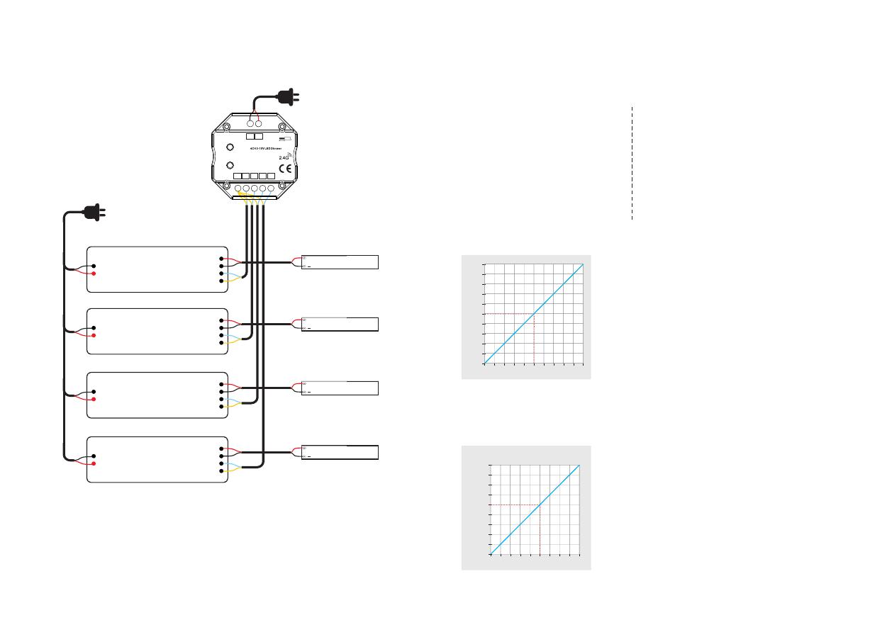
Wiring diagram
AC100-240V
Power input
V+
V-
DIM+
DIM-
ACN
ACL 0-10V Dimmable Driver
AC110-220V
V+
V-
DIM+
DIM-
ACN
ACL
V+
V-
DIM+
DIM-
ACN
ACL
V+
V-
DIM+
DIM-
ACN
ACL
0-10V Dimmable Driver
+
Single color LED strip
+
Single color LED strip
+
Single color LED strip
+
Single color LED strip
Match Remote Control (two match ways)
Use On/Off key
Match:
Turn on light, turn off, immediately press the On/Off
key of the panel for 5s,
then press any zone key of the RF remote within 5s.
The LED indicator fast flash 3 times
means match is successful.
Use Power Restart
Match:
Switch off the power, then switch on power, repeat again,
Immediately short press any zone key 3 times on the remote.
The light blinks 3 times means match is successful.
.
Delete:
Switch off the power, then switch on power, repeat again,
Immediately short press any zone key 5 times on the remote.
The light blinks 5 times means all matched remotes were
deleted.
Delete:
Turn on light, turn off, immediately press the On/Off
key of the panel for 10sto delete all match,
The LED indicator fast flash 6 times
means all matched remotes were deleted.
End user can choose the suitable match/delete ways. Two options are offered for selection:
T18-1 4 Channel 0-10V Touch Glass Panel Dimmer
The 0-10V touch panel dimmer can also match with the RF 4 zone dimming remote (optional).
Dimming curve
100
90
80
70
60
50
40
30
20
10
PWM duty(%)
50 60 70 80 90 100
Brightness(%)
10 20 30 40
10.0
9.0
8.0
7.0
6.0
5.0
4.0
3.0
2.0
1.0
0-10V level(V)
5V 6V 7V 8V 9V 10V2V 3V 4V
100%
90%
80%
70%
60%
50%
40%
30%
20%
10%
1V
out p u t curr e n t
Dimming input
Note:
When the output channel is off, the output dimming signal is 0V.
Please read the dimming section of the 0/1-10V dimming driver manual.
If the dimming characteristic curve is the same as below,
it will not be able to turn off the lights, you need select other models of 1-10V dimmer which have AC OUT function.
LN
INP UT 100- 24 0VAC
GND
0.5-2.0mm²
4-5mm
T1 8- 1
RoHS
4
3
Temp Ra nge: -3 0~+55
Uin =10 0- 240 VAC
Uou t=4x( 0-10V ) Signa l
Iou t=4x2 0mA max.
OUT PU T 0-1 0V SIGN AL
21
/