Page is loading ...

220-00085
Vertical Lifeline Instruction
Manual
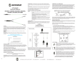
5/8” 100% Polyester Rope / Steel Hardware
Elongation: 8% at 1,800 lbs.
Elongation: 5% at 1,800 lbs.
5/8” Copolymer Rope / Steel Hardware
V5.0 2023 Copyright Safewaze

ANSI Z359.15
Capacity 130-310 lbs.
Lifeline Ø 7/16”(11-12mm)
Static Rope
225 Wilshire Ave SW
Concord, NC 28025
(800) 230-0319
www.safewaze.com
DO NOT REMOVE LABEL
MODEL #: 018-7005
DESCRIPTION: V-Line 50' Vertical Lifeline Assembly: Snap Hook,
Rope Grab, 3FT Lanyard
SERIAL #: XXXXXXXX MFG DATE: XX/XXXX
LIFELINE LENGTH: 50 ft. (15 m)
LIFELINE DIAMETER: 5/8 in. (16 mm)
COMPONENT(S): Rope Lifeline, Snap hook, Energy absorbing lanyard
MATERIALS: Copolymer rope; steel hardware, polyester webbing
CAPACITY: ANSI 130-310 lbs. (59-141 kg), OSHA up to 420 lbs. (191 kg)
MAXIMUM DEPLOYMENT DISTANCE: ANSI 48 in. (1219 mm),
OSHA 42 in. (1067 mm)
MAXIMUM ELONGATION: 7% at 1800 lbs. (8 kN)
AVERAGE ARREST FORCE: 900 lbs. (4 kN)
MAXIMUM ARREST FORCE: 1800 lbs. (8 kN)
MINIMUM BREAKING STRENGTH: 5000 lbs. / 22.25 kN
Standards: ANSI Z359.15-2014 & Z359.13-2013
OSHA 1926.502 & 1910.66
7/16” Kernmantle Rope / Steel Hardware
7/16” Kernmantle Rope / Steel Hardware / 420 lbs. Capacity
5/8” Kernmantle Rope / Steel Hardware
Associated VLL Components
Elongation: 12.5% at 1,800 lbs.
Elongation: 7% at 1,800 lbs.
Elongation: 6% at 1,800 lbs.
This manual is intended to meet the manufacturer’s instructions as required by ANSI Z359.15-2014 and should be used as part
of an employee training program as required by OSHA.
V5.0 2023 Copyright Safewaze

Do not throw away these instructions!
Read and understand these instructions before using equipment!
V5.0 2023 Copyright Safewaze
User must read, understand, and follow all safety and usage information contained within this manual prior to use of this equipment. Failure to follow
all safety and usage information can result in serious injury or death.
WARNINGS AND IMPORTANT PRECAUTIONS
Intended Use:
The equipment covered in this manual is intended for use as part of a complete Personal Fall Arrest System (PFAS). Use of this equipment for any other purpose,
such as material handling, sports activities, or other action not described in these User Instructions is not approved by Safewaze. Use of this equipment in a
manner outside the scope of those covered within this manual can result in serious injury or death. The equipment covered in this manual is only to be used by
trained personnel in workplace applications.
WARNING
IMPORTANT
This equipment is part of a complete PFAS. Every user must be trained in the inspection, installation, operation, and proper usage of their complete PFAS.
Unapproved or inappropriate use of Safewaze equipment could result in serious injury or death. Refer to these instructions for the proper selection, installation,
maintenance, and service of this equipment. For questions regarding use of this equipment beyond the scope of this manual, contact Safewaze.
The warnings below are designed to reduce the risks associated with the use of a Safewaze Vertical Rope Lifeline System:
• DO NOT alter this equipment.
• DO NOT attempt to modify this equipment.
• DO NOT use this equipment in any way not described in this manual.
• Exposure of this equipment to chemicals, high heat, severe cold, or other harsh environments may produce a harmful effect. If in doubt of suitable conditions
contact Safewaze.
• Avoid use of this equipment around moving machinery and electrical hazards.
• Avoid use of this equipment near sharp and abrasive surfaces.
• Improper use of this equipment, not following instructions or markings, may cause serious injury or death.
• Frequency of periodic inspection by a Competent Person other than the user should be established by the user’s organization based upon careful
consideration of relevant factors. Such factors include the nature and severity of workplace conditions affecting the equipment and the modes of use and
exposure time of the equipment.
• Inspect all equipment prior to each use.
• The equipment must be inspected annually by Competent Person other than the user. These results must be documented.
• If the users fall arrest subsystem is comprised of components from different manufacturers, the competent person must determine that all components are
compatible. Ensure that components meet all applicable standards and/or regulations for the work being performed.
• This equipment is designed for Fall Protection/Fall Arrest applications only.
• Unless explicitly stated otherwise, the maximum allowable free fall distance for lanyards must not exceed 6’.
• NEVER use fall protection equipment of any kind to hang, lift, support, or hoist tools or equipment, unless explicitly certied for such use.
• Physical harm may still occur even if fall safety equipment functions correctly. Sustained post-fall suspension may result in serious injury or death. Use trauma
relief straps to reduce the eects of suspension trauma.
• Fall protection equipment that fails inspection must be removed from service and tagged “Unusable.” The equipment should then be returned to Safewaze
for repair / service (if applicable) or destroyed. For questions regarding service/repair of components, contact Safewaze.
• Never exceed the maximum allowable weight capacity of your fall protection equipment.
• Never exceed the maximum free fall distance of your fall protection equipment.
• Only Safewaze, or entities authorized in writing by Safewaze, may make repairs to Safewaze fall protection equipment.
• User(s) of Safewaze fall protection equipment must ensure that their health and physical condition allows them to withstand all forces and potential risks
associated with working at heights. ANSI limits the weight capacity of fall protection equipment to a maximum of 310 lbs. Some equipment covered in this
manual may indicate a weight capacity in excess of 310 lbs. Heavier users are at an increased risk of serious injury or death due to increased forces on the
body during a fall and the risk for accelerated onset of suspension trauma. Pregnant women and minors must not use this equipment.
• Use of a body belt is NOT authorized for fall arrest applications. Use only a Full Body Harness (FBH).
• Always wear proper Personal Protective Equipment (PPE) when installing, using, or inspecting this equipment.
• If conducting training operations with this equipment, ensure that a secondary fall protection system is installed and utilized in a manner that does not expose
the trainee to unintended fall hazards.
• Immediately seek medical attention in the event a worker suffers a fall arrest incident.
• Avoid objects, equipment, or surfaces that could harm the user or equipment.
• User must ensure that there is adequate fall clearance when working at height.
• Extra precautions must be taken if working in the vicinity of moving machinery, electrical hazards, chemical hazards, sharp edges, explosive or toxic gases,
extreme temperatures, or below overhead equipment or materials that could impact the user and their fall protection equipment.
• If work is conducted in a high heat environment, ensure that Arc Flash or other suitable fall protection equipment is utilized.
• Safewaze equipment is designed for, and tested with, Safewaze components. If substitutions or replacements are made to the system, ensure all
components meet the applicable ANSI requirements.
Users should enact the precautionary measures listed below to reduce the inherent risks of working at height:
These instructions shall be provided to the user. User must read, understand, and follow all safety and usage information contained within this manual
prior to use of this equipment. Failure to follow these instructions or improper use can result in serious injury or death.
Equipment subjected to forces of fall arrest must immediately be removed from use.
Workplace conditions, including, but not limited to, ame, corrosive chemicals, electrical shock, sharp objects, machinery, abrasive substances, weather conditions,
and uneven surfaces, must be assessed by a Competent Person before fall protection equipment is selected. The inspection of the workplace must anticipate
where workers will be performing their duties, the routes they will take to reach their work, and the potential and existing fall hazards they may be exposed to. Fall
protection equipment must be chosen by a Competent Person. Selections must account for all potential hazardous workplace conditions. All fall protection
equipment should be purchased in new and unused condition.
Always verify the latest revision of the Safewaze Manual is being utilized. Visit the Safewaze website, or contact Customer Service, for updated manuals.

TABLE OF CONTENTS
1.0 INTRODUCTION .................................................................................... 5
2.0 APPLICATION ........................................................................................ 5
3.0 APPLICABLE SAFETY STANDARDS .................................................... 5
4.0 WORKER CLASSIFICATIONS ............................................................... 5
5.0 PURPOSE .............................................................................................. 5
6.0 SPECIFICATIONS .................................................................................. 5
7.0 PRODUCT SPECIFIC APPLICATIONS .................................................. 6
8.0 LIMITATIONS .......................................................................................... 6
9.0 COMPATIBILITY OF CONNECTORS..................................................... 6
10.0 MAKING CONNECTIONS ...................................................................... 7
11.0 COMPONENTS ...................................................................................... 7
12.0 ROPE GRABS ........................................................................................ 8
13.0 ROPE TERMINATION PLATE INSTALLATION ..................................... 14
14.0 ROPE PROTECTOR INSTALLATION ................................................... 15
15.0 5 LB. ROPE COUNTERWEIGHT INSTALLATION ................................ 15
16.0 INSPECTION ........................................................................................ 15
17.0 MAINTENANCE, CLEANING, & STORAGE ......................................... 16
18.0 LABELING ............................................................................................. 17
Do not throw away these instructions!
Read and understand these instructions before using equipment!
User Information
Date of First Use:
Serial#:
Trainer:
User:
V5.0 2023 Copyright Safewaze

Thank you for purchasing a Safewaze Vertical Rope Lifeline (VLL). This manual must be read and understood in its entirety and used as part of an employee
training program as required by OSHA or any applicable state agency. This manual and any other instructional material must be available to the user of the
equipment. The user must understand how to use the VLL safely and eectively, as well as any related Personal Fall Arrest System (PFAS) components.
When used according to instructions, this product meets OSHA 1926.502, 1910.140 and ANSI Z359.15-14, Z359.13-2013.
Safewaze VLLs are ANSI Z359.15-2014 compliant when used with an appropriate energy absorber and lanyard. Applicable standards and regulations
depend on the type of work being done, and also might include state-specic regulations. Refer to local, state, and federal (OSHA) requirements for additional
information concerning the governing of occupational safety regarding Personal Fall Arrest Systems (PFAS).
1.0 INTRODUCTION
2.0 APPLICATION
3.0 APPLICABLE SAFETY STANDARDS
6.0 SPECIFICATIONS
Safewaze VLLs are designed for use as part of a complete personal fall protection and/or restraint system. This product is designed for a single user whose
weight (including clothing, tools, and equipment) is:
ANSI 130-310 lbs. (59-141 kg)
OSHA Up to 420 lbs. (191 kg) / for 021-7019, 021-7020, 021-7021, 021-7022
4.0 WORKER CLASSIFICATIONS
Understand the denitions of those who work in proximity of or may be exposed to fall hazards or rescues.
5.0 PURPOSE
Vertical Rope Lifelines are used as part of a PFAS. VLLs are NOT authorized for use as a lifeline constituent of any Horizontal Lifeline System (HLL). They can
be used in conjunction with an HLL system where the VLL is connected to the Horizontal Lifeline and used in a vertical orientation as authorized. Roof structures
must have a minimum 2/12 pitch for use of a Safewaze Vertical Rope Lifeline. Do not use on a at roof unless use is for Fall Restraint purposes only.
The structure to which the system is attached must be capable of withstanding force in all directions permitted by the system.
To attach more that 1 system to a single anchorage, the 5,000 lbs. requirement must be multiplied by the number of systems attached to the anchorage.
Anchorage:
Rope Lifeline:
ANSI 5,000 lbs. (22.2 kN)
Min. Breaking Strength 5,000 lbs. (22.2 kN)
Stretch/Elongation 8.5% at 1,800 lbs.
Rope Melting Point 500°F (260°C)
Rope Tensile Strength 7,500 lbs.
Min. Breaking Strength 5,000 lbs. (22.2 kN)
Stretch/Elongation 7% at 1,800 lbs.
Rope Melting Point 275°F (135°C)
Rope Tensile Strength 7,500 lbs.
Min. Breaking Strength 5,000 lbs. (22.2 kN)
Stretch/Elongation 12.5% at 1,800 lbs.
Rope Melting Point 450°F (232°C)
Rope Tensile Strength 11,000 lbs.
Min. Breaking Strength 5,000 lbs. (22.2 kN)
Stretch/Elongation 6% at 1,800 lbs.
Rope Melting Point 450°F (232°C)
Rope Tensile Strength 8,200 lbs.
Min. Breaking Strength 5,000 lbs. (22.2 kN)
Stretch/Elongation 7% at 1,000 lbs.
Rope Melting Point 450°F (232°C)
Rope Tensile Strength 11,000 lbs.
Anchorage Connector:
Minimum Breaking Strength 5,000 lbs. (22.2kN)
5/8” 100% Polyester Rope 5/8” Copolymer Rope 5/8” Kernmantle Rope
7/16” Kernmantle Rope 7/16” Kernmantle Rope / Pro Series
Working Temperature Range:
Working Temperature Range -35°F (-37°C) to 130°F (54°C)
Qualied Engineer: “Qualied Engineer” means a person with a bachelor of science degree in engineering from an accredited college or university. They are able
to assume personal responsibility for the development and application of engineering science and knowledge in the design, construction, use, and maintenance of
their projects.
Qualied Person: “Qualied Person” means one who, by possession of a recognized degree, certicate, or professional standing, or who by extensive
knowledge, training, and experience, has successfully demonstrated their ability to solve or resolve problems relating to the subject matter, the work, or the project.
Competent Person: “Competent Person” means one who is capable of identifying existing and predictable hazards in the surroundings or working conditions
which are unsanitary, hazardous, or dangerous to employees, and who has authorization to take prompt corrective measures to eliminate them.
Authorized Person: “Authorized Person” means a person approved or assigned by the employer to perform a specic type of duty or duties, or to be at a specic
location or locations, at the jobsite.
It is the responsibility of a Qualied or Competent person to supervise the jobsite and ensure safety
regulations are complied with.
V5.0 2023 Copyright Safewaze Page 5

Personal Fall Arrest: Safewaze Vertical Lifelines can be used as part of a complete Personal Fall Arrest System (PFAS) for a maximum of one user. Only one
user may be connected to a VLL. Only one fall arrester is to be attached to the VLL at any given time. Avoid sharp and/or abrasive edges. If contact with an
abrasive surface is unavoidable, proper rope protection must be used. The structure utilized for attachment must be capable of withstanding a load of 5,000 lbs.
in all directions permitted by the system. The maximum allowable free fall is 6 ft., with the maximum combined length of the fall arrester, lanyard extension, and
D-ring being 36 inches.
Fall Clearance: There must be sucient clearance below the anchorage connector to arrest a fall before the user strikes the ground or an obstruction. When
calculating fall clearance, account for a MINIMUM 2’ safety factor, deceleration distance, user height, length of lanyard/SRL, and all other applicable factors
(Figure 1). Lanyards used with Safewaze rope grabs must be shock absorbing and no more than 36” in length.
Calculate Minimum Required Fall Clearance
Swing Falls: Prior to installation or use, make considerations for eliminating or minimizing all swing fall hazards. Swing falls occur when the anchor is not directly
above the location where a fall occurs. Always work as close to the anchor point as possible. Swing falls signicantly increase the likelihood of serious injury or
death in the event of a fall (Figure 2).
For all applications: Worker weight capacity range is 130-310 lbs (including all clothing, tools, and equipment)
FIGURE 1- FALL CLEARANCE
7.0 PRODUCT SPECIFIC APPLICATIONS
8.0 LIMITATIONS
A
FALL-ARREST
S
W
I
N
G
F
A
L
L
WARNING: AVOID SWING FALL HAZARDS ENCOUNTERED WHEN ANCHORAGE IS NOT DIRECTLY OVERHEAD.
FIGURE 2 - SWING FALL
Connectors are compatible with connecting elements when they have been designed to work together in such a way that their sizes and shapes do not cause
their gate mechanisms to inadvertently open regardless of how they become oriented. Connectors (hooks, carabiners, and D-rings) must be capable of supporting
at least 5,000 lbs. (22.2 kN). Connectors must be compatible with the anchorage or other system components (Figure 3). Do not use equipment that is not
compatible. Non- compatible connectors may unintentionally disengage (Figure 3). Connectors must be compatible in size, shape, and strength. Self-locking snap
hooks and carabiners are required by ANSI Z359 and OSHA guidelines. Contact Safewaze if you have any questions about compatibility.
9.0 COMPATIBILITY OF CONNECTORS
SAFETY FACTOR
Includes fall arrester slippage
2'
HARNESS STRETCH
18" Max. per ANSI Z359.11-2021
DECELERATION DISTANCE
48" Max. per ANSI Z359.13-2013
LANYARD LENGTH
Adjust when using different lengths
ROPE ELONGATION
10% of the length measured from the
anchorage to the fall arrester
HEIGHT OF WORKER
Measured from working surface to Dorsal D-
ring
TOTAL REQUIRED FALL CLEARANCE
FROM THE FALL ARRESTOR
5'
1.5'
4'
3'
X
V5.0 2023 Copyright Safewaze Page 6

Connect free end
of lanyard to the
rope grab via
snap hook
FIGURE 3 - UNINTENTIONAL DISENGAGEMENT
Using a connector that is undersized or irregular in shape (1) to connect a snap hook or carabiner could allow the connector to force open the gate of the snap
hook or carabiner. When force is applied, the gate of the hook or carabiner presses against the non-compliant part (2) and forces open the gate (3). This allows the
snap hook or carabiner to disengage (4) from the connection point.
10.0 MAKING CONNECTIONS
3 - Gate opens
2 - Gate presses
against
non-complaint part
4 - Parts disengage
1 - Non-compliant part
Snap hooks and carabiners used with this equipment must be double locking and/or twist lock. Ensure all connections are compatible in size, shape and strength.
Do not use equipment that is not compatible. Ensure all connectors are fully closed and locked. Safewaze connectors (snap hooks and carabiners) are designed
to be used only as specied in each product’s user’s instructions. See Figure 4 for examples of inappropriate connections as well as the correct connection of a
user to the VLL. NOTE: ALWAYS connect shock pack of lanyard to the user's dorsal D-ring! DO NOT connect shock pack to the rope grab!
Do not connect snap hooks and carabiners:
• To a D-ring to which another connector is attached.
• In a manner that would result in a load on the gate (with the exception of tie back hooks).
• NOTE: Large snap hooks must not be connected to objects which will result in a load on the gate if the hook twists or rotates. Hooks supplied with Safewaze
VLLs comply with ANSI Z359.12 and are equipped with a 3,600 lbs. (16 kN) gate. Check the marking on your snap hook to verify its compatibility.
• Without visual conrmation that the connection is secure and not a false engagement.
• To each other.
• By wrapping the web lifeline around an anchor and securing to lifeline except as allowed for tie back models.
• To any object which is shaped or sized in a way that the snap hook or carabiner will not close and lock, or that roll-out could occur.
• In a manner that does not allow the connector to align properly while under load.
INAPPROPRIATE CONNECTIONS CORRECT USER CONNECTION TO VLL
FIGURE 4 - MAKING CONNECTIONS
Connect shock
pack of lanyard
to user's
dorsal D-ring
5/8 in (16 mm)
Rope Lifeline
5/8 in (16 mm)
Rope Lifeline
Integral 3’Extension
Lanyard
Integral Manual
Rope Grab
Removable Fall Arrester
(Rope Grab)
Carabiner
Shock
Pack
Shock
Pack
Labels
Labels
Plastic
Thimble Eye
Plastic
Thimble Eye
Snap Hooks
Swivel
Snap Hook
V5.0 2023 Copyright Safewaze Page 7
11.0 COMPONENTS
FIGURE 5 - COMPONENTS

12.1 MANUAL ROPE GRAB OPERATION
UP
UP
5. The FS1117 rope grab is a non-removable manual rope grab for VLL operations. The FS1117 is typically pre-installed onto the VLL system prior to shipping.
2. User must be aware of, and seek to minimize, any swing fall hazards that may exist.
Stationary Position Movement Position
4. When used with an ANSI compliant Energy Absorbing Lanyard (EAL), the energy absorber attaches directly to the users appropriate D-ring, with the opposite
end of the lanyard attaching to the grab.
6. If the user desires to move along the lifeline they must ensure that they move the fall arrester along the rope lifeline in conjunction with their movements
(Figure 7). User should not move the lifeline while leaving the fall arrester stationary on the rope as this could result in unsafe slack forming along the lifeline
component. This slack can result in creating an unnecessary trip hazard, as well as possibly creating conditions where free fall levels permitted by the systems
are exceeded.
7. NEVER grab the Fall Arrester during a fall! Doing so may allow the unit to disengage and the Fall Arrester to slip along the Vertical Lifeline!
Squeeze Inward
and
Up Simultaneously
FIGURE 7- MANUAL ROPE GRAB MOVEMENT
“UP” Arrow
USER MUST ENSURE THE ROPE GRAB IS INSTALLED IN THE CORRECT ORIENTATION TO THE VERTICAL LIFELINE. INCORRECT INSTALLATION CAN
RESULT IN SERIOUS INJURY OR DEATH!
ONLY ONE USER CAN BE ATTACHED TO THE SINGLE ANCHOR LIFELINE!
FIGURE 6 - ROPE GRAB ALLOWED ANGLE OF USE
max 30°
Maximum working angle between
user and device must not exceed
30°.
NEVER work above the device!
V5.0 2023 Copyright Safewaze
12.0 ROPE GRABS
TABLE 1- ROPE GRABS
Page 8
Safewaze rope grabs are designed to work with specic rope sizes and types. All grabs are equipped with an “UP” Arrow, which indicates the proper orientation of
the grab to the Vertical Rope Lifeline (Figure 7). Some models are also equipped with an anti-inversion feature which prevents the grab from being installed upside
down. Table 1 indicates the available rope grabs, suitable rope, and appropriate shock absorbing lanyard.
Rope Grab Rope Sizing and Type Shock Absorber / Lanyard
FS1117 (Manual Rope Grab) 5/8” Polyester or Copolymer Rope ANSI compliant 3' shock absorbing lanyard
FS1118 (Trailing SS Rope Grab) 5/8” Polyester, Copolymer or Low Stretch Kernmantle Rope ANSI compliant 3' shock absorbing lanyard
FS1118-DC (Self-Tracking Rope Grab) 5/8” Copolymer or Low Stretch Kernmantle ANSI compliant 3' shock absorbing lanyard
FS1120 (Trailing Rope Grab) 5/8” Polyester, Copolymer or Kernmantle Rope ANSI compliant 3' shock absorbing lanyard
SW-EX8000 (Trailing Rope Grab) 7/16” Low Stretch Kernmantle Rope ANSI compliant 3' shock absorbing lanyard
021-7022 (Trailing Rope Grab) 7/16” Low Stretch Kernmantle Rope ANSI compliant 3' shock absorbing lanyard
022-7025 (Drift Rope Grab) 7/16” Low Stretch Kernmantle Rope ANSI compliant 3' shock absorbing lanyard
FS1117
1. User must inspect the FS1117 for any obvious signs of damage or defects prior to each use.
3. Ensure adequate fall clearance exists for the equipment being used and associated work operations
DO NOT USE THIS EQUIPMENT WHEN THE USER IS ON AN UNSTABLE SURFACE, FINE GRAIN MATERIAL, OR PARTICULATE SOLIDS SUCH AS SAND
OR COAL!
AVOID USE OF THIS EQUIPMENT IN PROXIMITY TO MOVING EQUIPMENT AND ELECTRICAL HAZARDS!
DO NOT USE COMBINATIONS OF FALL ARRESTERS, LANYARDS, AND LIFELINES WHICH MAY AFFECT OR INTERFERE WITH THE SAFE FUNCTION OF
EACH OTHER!
WARNING

4. When used with an ANSI compliant Energy Absorbing Lanyard (EAL), the energy absorber attaches directly to the users appropriate D-ring, with the opposite
end of the lanyard attaching to the grab.
5. The FS1118 and FS1120 are equipped with an anti-inversion cam in the hinge. This prevents the grab from opening or closing if in the wrong orientation
relative to the rope. When installing, ensure that the etched arrow is pointing up (Figure 8). NEVER grab the Fall Arrester during a fall! However, the FS1118
and FS1120 are equipped with an Anti-Panic feature. This allows the grab to function normally if inadvertently grabbed during a fall.
6. Figure 9 details how to properly connect and operate the FS1118 and FS1120 grabs on the Vertical Rope Lifeline.
7. NEVER grab the Fall Arrester during a fall! Doing so may allow the unit to disengage and the Fall Arrester to slip along the Vertical Lifeline!
Step 1: Rotate safety
lever all the way up.
Step 2: Loosen the
knurled locking knob.
Step 5: Close the
gate, and re-tighten the
knurled locking knob.
Step 6: Rotate the
safety lever all the way
down.
Step 3: Open the
hinged gate of the grab.
Step 4: Lift the ring
up to retract the cam
assembly, and place the
rope into the channel.
“UP” Arrow
V5.0 2023 Copyright Safewaze Page 9
12.2 TRAILING ROPE GRAB INSTALLATION AND OPERATION FS1118 & FS1120
1. User must inspect the FS1118 and FS1120 for any obvious signs of damage or defects prior to each use.
2. User must be aware of, and seek to minimize, any swing fall hazards that may exist.
3. Ensure adequate fall clearance exists for the equipment being used and associated work operations.
FS1118 & FS1120
FIGURE 9- TRAILING ROPE GRAB INSTALLATION AND OPERATION
OPERATION
FIGURE 8 - ROPE GRAB ORIENTATION FOR INSTALL

12.3 SELF-TRACKING ROPE GRAB INSTALLATION
5. The FS1118-DC is a removable self-tracking rope grab for VLL operations. The FS1118-DC installs in virtually the same manner as the FS1118 and FS1120.
The only dierence being the rst step in the process. Rather than rotating the safety lever all the way up as done with the FS1118 and FS11120, simply push
in on the safety lever to begin loosening the knurled locking knob (Figure 10).
6. The FS1118-DC is also equipped with an anti-inversion cam in the hinge. This prevents the grab from opening or closing if in the wrong orientation relative to
the rope. When installing, ensure that the arrow is pointing up (Figure 10).
7. NEVER grab the Fall Arrester during a fall! Doing so may allow the unit to disengage and the Fall Arrester to slip along the Vertical Lifeline!
FIGURE 10 - NON-TRAILING ROPE GRAB INSTALL
4. When used with an ANSI compliant Energy Absorbing Lanyard (EAL), the energy absorber attaches directly to the users appropriate D-ring, with the opposite
end of the lanyard attaching to the grab.
1. User must inspect the FS1118-DC and FS1120 for any obvious signs of damage or defects prior to each use.
2. User must be aware of, and seek to minimize, any swing fall hazards that may exist.
3. Ensure adequate fall clearance exists for the equipment being used and associated work operations
Safety Lever Push Inward
“UP” Arrow
5. Ensure the SW-EX8000 is in correct orientation to the VLL with the indicator arrow pointing up (Figure 11). Rotate the sliding plate open and verify the locking
wheel is in the GO position (Step 1).
6. Insert the rope ensuring the device remains the correct vertical orientation (Step 2).
7. Rotate the sliding plate closed (Step 3).
8. Install an ANSI Z359.12 compliant connector through the connection slot (Step 4).
9. Pull upward on the connector to verify that the rope grab moves freely along the lifeline (Step 5).
10. Proper function of the SW-EX8000 can be tested by again pulling up on the connector, and then rapidly pulling downward to ensure the grab locks onto the
rope and stops (Step 6). Figure 11 illustrates proper installation of the SW-EX8000.
FIGURE 11 - INSTALLATION
REST
100kg
GO
EASY
MOVE
Rope Lock
Connection Slot
“UP” Arrow
VLL Anchor Point
Free End of VLL
Ø 7/16" (11-12mm)
Kernmantle Rope
12.4 TRAILING ROPE GRAB INSTALLATION AND OPERATION SW-EX8000
4. When used with an ANSI compliant Energy Absorbing Lanyard (EAL), the energy absorber attaches directly to the users appropriate D-ring, with the opposite
end of the lanyard attaching to the grab.
1. User must inspect the SW-EX8000 for any obvious signs of damage or defects prior to each use.
2. User must be aware of, and seek to minimize, any swing fall hazards that may exist.
3. Ensure adequate fall clearance exists for the equipment being used and associated work operations
V5.0 2023 Copyright Safewaze Page 10
FS1118-DC

The SW-EX8000 allows for safe and hands free climbing on vertical structures. In the event of an accident, any fall will be immediately arrested. It is necessary to
use this device in combination with a shock absorber to be ANSI Z359.15-2014 compliant. The user must always ensure they are at a lower level than the
SW-EX8000. Maximum working angle between user and device must not exceed 30°.
User must ensure the VLL does not come into contact with any sharp or abrasive surfaces. The SW-EX8000 will automatically trail the user as they move up and
down the VLL. To stop the trailing function of the SW-EX8000 rotate the locking wheel to REST position. As the user needs to move up or down the VLL, they must
rotate the locking wheel back to the GO position.
To remove the SW-EX8000 from the VLL, disconnect the carabiner from the connection slot of the grab and rotate the sliding plate open. DO NOT ATTEMPT TO
DISCONNECT WHILE IN USE!!
STOP!
GO
REST
Step 1: Step 2: Step 3: Step 4: Step 5: Step 6:
6. Insert the rope ensuring the device remains the correct vertical orientation (Step 2).
5. Rotate the sliding plate open and verify that the position of the rope lock is in the GO position (Step 1).
7. Rotate the sliding plate closed (Step 3).
8. Install an ANSI Z359.12 compliant connector through the connection slot (Step 4).
9. Pull upward on the connector to verify that the rope grab moves freely along the lifeline (Step 5).
10. Proper function of the 021-7022 can be tested by again pulling up on the connector, and then rapidly pulling downward to ensure the grab locks onto the rope
and stops (Step 6). Figure 12 illustrates proper installation of the 021-7022.
ANSI Z359.15
Capacity 130-310 lbs.
Lifeline Ø 7/16”(11-12mm)
Static Rope
Rope Lock
Connection Slot
FIGURE 12 - INSTALLATION
“UP” Arrow
VLL Anchor Point
Free End of VLL
Ø 7/16" (11-12mm)
Kernmantle Rope
ANSI Z359.15
Capacity 130-310 lbs.
Lifeline Ø 7/16”(11-12mm)
Static Rope
"Go"
Position
ANSI Z359.15
Capacity 130-310 lbs.
Lifeline Ø 7/16”(11-12mm)
Static Rope
"Rest/Park"
Position
12.5 TRAILING ROPE GRAB INSTALLATION AND OPERATION 021-7022
4. When used with an ANSI compliant Energy Absorbing Lanyard (EAL), the energy absorber attaches directly to the users appropriate D-ring, with the opposite
end of the lanyard attaching to the grab.
1. User must inspect the 021-7022 for any obvious signs of damage or defects prior to each use.
2. User must be aware of, and seek to minimize, any swing fall hazards that may exist.
3. Ensure adequate fall clearance exists for the equipment being used and associated work operations
V5.0 2023 Copyright Safewaze Page 11
WARNING: AVOID LIFELINE EXPOSURE TO PHYSICAL AND CHEMICAL HAZARDS WHICH THE LIFELINE IS NOT
DESIGNED TO WITHSTAND.

ANSI Z359.15
Capacity 130-310 lbs.
Lifeline Ø 7/16”(11-12mm)
Static Rope
ANSI Z359.15
Capacity 130-310 lbs.
Lifeline Ø 7/16”(11-12mm)
Static Rope
Step 1:
ANSI Z359.15
Capacity 130-310 lbs.
Lifeline Ø 7/16”(11-12mm)
Static Rope
Step 2:
ANSI Z359.15
Capacity 130-310 lbs.
Lifeline Ø 7/16”(11-12mm)
Static Rope
Step 3: Step 4:
ANSI Z359.15
Capacity 130-310 lbs.
Lifeline Ø 7/16”(11-12mm)
Static Rope
Step 6:
ANSI Z359.15
Capacity 130-310 lbs.
Lifeline Ø 7/16”(11-12mm)
Static Rope
Step 5:
The 021-7022 allows for safe and hands free climbing on vertical structures. In the event of an accident, any fall will be immediately arrested. It is necessary to use
this device in combination with a shock absorber to be ANSI Z359.15-2014 compliant. The user must always ensure they are at a lower level than the 021-7022.
Maximum working angle between user and device must not exceed 30°. The 021-7022 when used as part of a complete VLL system has a maximum capacity for
one user of up to 420 lbs.
User must ensure the VLL does not come into contact with any sharp or abrasive surfaces. The 021-7022 will automatically trail the user as they move up and
down the VLL. To stop the trailing function of the 021-7022 rotate the locking lever to PARK/REST position. As the user needs to move up or down the VLL, they
must rotate the locking lever back to the GO position.
To remove the 021-7022 from the VLL, disconnect the carabiner from the connection slot of the grab and rotate the front plate open. DO NOT ATTEMPT TO
DISCONNECT WHILE IN USE!!
STOP!
5. Verify the position of the mode control switch is in the Trail position (Dwg. 3). With the sliding plate open, install the drift grab onto the VLL, ensuring the device
remains in the correct vertical orientation designated by an UP arrow (Dwg. 4).
6. Rotate the sliding plate closed over the VLL. Make sure the red dot warning indicator is not visible on the plate gate (Dwg. 5).
7. When used with an ANSI compliant Energy Absorbing Lanyard (EAL), the energy absorber’s snap hook attaches directly to the User’s Dorsal D-ring, with the
D-ring end of the lanyard attaching to the rope grab’s carabiner. Connect the EAL to the installed rope grab’s carabiner. (Dwg. 6).
8. Pull upward on the connector to verify that the rope grab moves freely along the lifeline (Dwg. 7).
9. Proper function of the 022-7025 can be tested by again pulling up on the connector, and then rapidly pulling downward to ensure the grab locks onto the rope
and stops (Dwg. 8).
12.6 DRIFT ROPE GRAB INSTALLATION AND OPERATION 022-7025
4. Rotate the sliding plate open by pushing the green plate gate to the left, while simultaneously pressing the red button. (Dwgs. 1 & 2). The 022-7025 was
designed for maximum eciency and allows the sliding plate to open and close without removing the carabiner from the grab.
1. User must inspect the 022-7025 for any obvious signs of damage or defects prior to each use. Figure 13 illustrates the components of the 022-7025.
2. User must be aware of, and seek to minimize, any swing fall hazards that may exist.
3. Ensure adequate fall clearance exists for the equipment being used and associated work operations
FIGURE 13 - COMPONENTS
“UP” Arrow
VLL Anchor Point
Free End of VLL
Ø 7/16" (11-12mm)
Kernmantle Rope
Mode
Control
Switch
Connection Slot
Sliding Plate
Plate Lock
(Red Button)
Green Sliding
Gate
V5.0 2023 Copyright Safewaze Page 12
FALL PROTECTION SYSTEMS MUST BE SELECTED AND INSTALLED UNDER THE SUPERVISION OF A COMPETENT PERSON AND USED IN A
COMPLIANT MANNER. FALL PROTECTION SYSTEMS MUST BE DESIGNED IN A MANNER COMPLIANT WITH ALL FEDERAL, STATE, AND SAFETY
REGULATIONS. FORCES APPLIED TO ANCHORS MUST BE CALCULATED BY A COMPETENT PERSON.
IF EQUIPMENT IS EXPOSED TO CHEMICAL HAZARDS THAT MAY CAUSE ANY DAMAGE OR DEGRADATION, EQUIPMENT MUST BE REMOVED FROM
SERVICE. IF IN DOUBT, CONTACT SAFEWAZE.
EQUIPMENT SUBJECTED TO FORCES OF A FALL ARREST MUST IMMEDIATELY BE REMOVED FROM USE.
WARNING

WARNING INDICATOR
The 022-7025 allows for safe and hands free climbing on vertical structures. In the event of an accident, any fall will be immediately arrested. It is necessary to use
this device in combination with a shock absorber to be ANSI Z359.15-2014 compliant. The user must always ensure they are at a lower level than the 022-7025.
Maximum working angle between user and device must not exceed 30°. NEVER work above the device!
User must ensure the VLL does not come into contact with any sharp or abrasive surfaces. The Drift Rope Grab will automatically trail the user as they move up
and down the VLL. To stop the trailing function of the 022-7025, rotate the mode control switch to the HOLD position. As the user needs to move up or down the
VLL, they must rotate the mode control switch back to the TRAIL position (Dwg. 3).
To remove the Drift Rope Grab from the VLL, rotate the sliding plate open (Figure 14). DO NOT ATTEMPT TO DISCONNECT WHILE IN USE!!
Dwg. 6: Dwg. 7: Dwg. 8:
STOP!
Dwg. 5:
FIGURE 14 - DISCONNECTION FROM VLL
Dwg. 2:
Dwg. 1:
TRAIL
and
HOLD
Mode Control
Switch
Dwg. 3:
Dwg. 4:
The Drift Rope Grab is suitable for use in rescue operations. However, if used to facilitate descent to an injured worker, the Backup Anchor Descent Cord should be
utilized. The Backup Anchor Descent Cord is simple to install and is included with the grab at time of shipment.
To install the Backup Anchor Descent Cord, tie a knot at one end of the cord. Thread the untied end of the cord through the pre-drilled hole on the grab from the
inside out. Pull the cord through the hole until the knotted end of the rope cinches against the plate of the grab.
Figure 15 illustrates the proper installation and use of the Backup Anchor Descent Cord.
12.6 DRIFT ROPE GRAB (USE IN ASSISTED RESCUE) 022-7025
V5.0 2023 Copyright Safewaze
Page 12 Page 13

FIGURE 16 - FS875 ROPE TERMINATION PLATE INSTALLATION
12
1
8
”
34
13.0 ROPE TERMINATION PLATE INSTALLATION
If the VLL is unequipped with connecting hardware, the FS875 can be used to provide a safe connection to the anchorage. The FS875 can be used with 5/8” or
3/4” rope. Figure 16 illustrates the installation steps for the FS875.
FS875
Backup Anchor
Descent Cord
Installation Hole
Backup Anchor
Descent Cord
Installation Hole
FIGURE 15 - BACKUP ANCHOR DESCENT CORD INSTALLATION AND USE
Knotted end
of Backup
Anchor
Descent Cord
Knotted end
of Backup
Anchor
Descent Cord
Free end
of Backup
Anchor
Descent Cord
Backup Anchor
Descent Cord
The Drift Rope Grab, when used in rescue operation, will rotate to the HOLD orientation on the rope lifeline simply due to the rescuer's weight. Pull down on
Backup Anchor Descent Cord to descend. Placing tension on the Backup Anchor Descent Cord orients the Drift Rope Grab in a more perpendicular position on the
rope lifeline. This allows the rope to travel through the grab allowing the user to descend.
V5.0 2023 Copyright Safewaze Page 14

14.0 ROPE PROTECTOR INSTALLATION 018-9000 / 018-9001
Great care should be taken to ensure the lifeline does not come into contact with any type of edge or rough abrasive surfaces. Contact with any edge or rough
abrasive surfaces requires abrasion protection (Figure 17).
1. The 018-9000 / 018-9001 rope protectors are suitable for use with any type of rope lifeline.
2. The 018-9000 rope protector is 18” (45.72 cm) long. The 018-9001 rope protector is 36” (91.44 cm) long. Both sizes have sewn in hook and loop fastener
material along the entire length of the protector.
3. Place rope into the protector by pulling apart the hook and loop fastener along the length of the protector.
4. After opening up the protector, position the protector on the rope where it will be required, and enclose the rope in the protector by resealing the hook and
loop fastener. Each protector has a sewn in web loop at either end for attachment to the rope lifeline. Attachment can be performed with a small bungee style
cord, plastic zip tie, or with an alpine buttery knot and carabiner.
5. Figure 17 indicates the 018-9000 / 018-9001 in typical installation congurations.
FIGURE 17 - EDGE PROTECTOR TYPICAL USE EXAMPLE
15.0 5 LB. ROPE COUNTERWEIGHT INSTALLATION 021-7014
VLLs must remain taut during work operations. Connect the free (non-anchorage) end of the rope lifeline to a minimum 5 lbs. counterweight, such as the
021-7014 (Figure 18). Allow the counterweight to swing freely at the end of the VLL. User must ensure the free end of the VLL is equipped with a stitched
termination, appropriate knot, or other method, to prevent the grab from traveling o the end of the VLL.
FIGURE 18 - 021-7014 ROPE COUNTERWEIGHT INSTALLATION
123 4
V5.0 2023 Copyright Safewaze Page 15
WARNING: AVOID USE OF THIS EQUIPMENT NEAR EDGES OR ABRASIVE SURFACES. IF UNAVOIDABLE,
ENSURE PROPER EQUIPMENT IS USED TO PROTECT THE VLL.
16.0 INSPECTION
USER MUST KEEP INSTRUCTIONS AVAILABLE FOR REFERENCE. Record Date of First Use.
User’s inspection must be equal to or greater than those indicated in these instructions.
Rope: Prior to each use, inspect the rope for possible deciencies/damage including, but not limited to, fraying, cuts, corrosion, chemical exposure, melting or
damage due to heat, welding, or ame exposure, unsplicing, unlaying, kinking, knotting, broken or pulled stitches, excessive elongation, excessive soiling,
abrasion, alteration, excessive lubrication, excessive aging, excessive wear, and missing or illegible labels.
Hardware: Prior to each use, inspect hardware for possible deciencies/damage including but not limited to, cracks, sharp edges, deformation, corrosion,
chemical exposure, excessive heating, alteration, and excessive wear.
Fall Arrester (Rope Grab): Prior to each use, inspect hardware for possible deciencies/damage including but not limited to, cracks, sharp edges, deformation,
corrosion, chemical exposure, excessive heating, alteration, proper function (no movement in stationary mode, free movement in movement mode), excessive
wear, and missing or illegible labels.

Rope
Rope
Lanyard/Webbing
Fall Arrester
(Rope Grab)
Fall Arrester
(Rope Grab)
Hardware
Shock
Pack
Shock
Pack
Labels
Labels
Plastic
Thimble Eye
Plastic
Thimble Eye
Hardware
Hardware
FIGURE 19 - INSPECTION DIAGRAMS
V5.0 2023 Copyright Safewaze Page 16
Inspect work area to ensure that location is free of any damage including, but not limited to, debris, cracking, rot, decay, structural deterioration, rust, and free from
any hazardous materials. Inspect to ensure no elements are missing that may aect the equipment form, t, or function. User must conrm that work area to be
utilized will support the application specic loads as referenced within this instruction manual and as per ANSI and OSHA.
At least annually, a Competent Person other than the user must inspect the Vertical Lifeline and/or Fall Arrester (Rope Grab).
Competent Person inspections must be recorded on the inspection log included in this manual (Page 19) as well as the inspection table labels on each product
individually. The Competent Person must place their initials in the block which corresponds with the month and year that the inspection is performed. All individual
labels on equipment will be initialed in the same manner.
While conducting inspections, the Competent Person must consider all applications and hazards the equipment may have been exposed to while in use.
User MUST IMMEDIATELY REMOVE from service ANY equipment that is found defective, damaged, or exposed to fall arrest forces. Damaged equipment must
be destroyed to prevent future use. Cut the VLL into sections and dispose of. Any equipment that is in need of maintenance or repair must be tagged and removed
from service. For questions regarding maintenance or repair contact Safewaze.
Use a dry cloth to brush and clean the rope grab. The rope lifeline, lanyard, rope protector can be cleaned with warm water and a mild soap solution. Dry the rope
grab with a clean rag. Allow other equipment to air dry. DO NOT USE HEAT TO DRY EQUIPMENT!
17.2 CLEANING
Remove equipment from use if subjected to fall arrest forces or inspection reveals an unsafe or defective condition. Should an unsafe or defective condition be
found, the equipment MUST immediately be removed from service. Dispose of damaged equipment per jobsite requirements. For questions regarding damaged
equipment, contact Safewaze.
17.0 MAINTENANCE, CLEANING, & STORAGE
17.1 MAINTENANCE
17.3 STORAGE
Store the Safewaze VLL System in a cool, dry, clean environment out of direct sunlight. Avoid areas where chemical vapors may exist. Thoroughly inspect the
system after any period of extended storage.

1) Manufacturer
2) Logo notifying users to carefully read and understand instructions
3) Part number
4) Serial Number
5) Up Arrow
6) Applicable Standards, Capacity, Suitable Rope Data
7) Proper Use Diagram
8) Warning
1
2
3
5
6
8
4
7
021-7022
ANSI Z359.15-2014
CAPACITY 130-310 lbs.
LIFELINE Φ7/16"(
11-12 mm)
STATIC ROPE
XXX
AA
Warning:
Must follow manufacturer's instructions.
Only manufacturer approved lanyards
may be used with this product.
1
2
3
45
AAAA-DDD-YY
0000
SW-EX8000
8
7
69
10
GO
REST
1) Number, year and applicable standards
2) Logo notifying users to carefully read and understand instructions
3) Part number
4) Batch number
5) Country of origin
6) Serial number
7) Correct use and maximum capacity
8) Product model
9) Manufacturer
10) Indication for position of the blocking wheel
REST: For use while stationary
GO: For use while moving along VLL / Fall Arrest mode
FIGURE 20 - LABELING
V5.0 2023 Copyright Safewaze Page 17
1
2
3
6
4
5
8
9
7
13
14
15
11
10
12
16
17
1) Manufacturer
2) Product model
3) Green Lock Safety Indicator
4) “UP” Arrow
5) Blocking Wheel
6) Red Button
7) Green Lock
8) Unlock Direction
9) Instructions for Unlocking
10) Number, year and applicable standards
11) Warnings
12) Maximum Weight Capacity
13) Batch Number
14) Part Number/Date of Manufacture
15) Logo notifying users to carefully read
and understand instructions
16) Overhead anchorage symbol
17) “UP” Arrow
18.0 LABELING
WARNING: This equipment must be inspected prior to
each use. Any unit that has been exposed to fall arrest
forces must be removed from service. Avoid contact with
sharp edges and abrasive surfaces. Only use compatible
connections. Do not subject this equipment to physical
hazards that include thermal, electrical, and chemical
sources. User must read, understand and follow all
manufacturer’s instructions included with this unit at the
time of shipment. Failure to follow these and any of the
manufacturer’s instructions may result in serious injury or
death.
Warning: Maximum User Weight 130-310 lbs.
6ft. 900lbs.
Maximum Free Fall Average Arresting Force
Forces may increase when cold and/or wet
Read Instructions Before Use
225 Wilshire Ave SW
Concord, NC 28025
(800) 230-0319
www.safewaze.com
DO NOT REMOVE LABEL
MODEL #: 018-7005
DESCRIPTION: V-Line 50' Vertical Lifeline Assembly: Snap Hook,
Rope Grab, 3FT Lanyard
SERIAL #: XXXXXXXX MFG DATE: XX/XXXX
LIFELINE LENGTH: 50 ft. (15 m)
LIFELINE DIAMETER: 5/8 in. (16 mm)
COMPONENT(S): Rope Lifeline, Snap hook, Energy absorbing lanyard
MATERIALS: Copolymer rope; steel hardware, polyester webbing
CAPACITY: ANSI 130-310 lbs. (59-141 kg), OSHA up to 420 lbs. (191 kg)
MAXIMUM DEPLOYMENT DISTANCE: ANSI 48 in. (1219 mm),
OSHA 42 in. (1067 mm)
MAXIMUM ELONGATION: 7% at 1800 lbs. (8 kN)
AVERAGE ARREST FORCE: 900 lbs. (4 kN)
MAXIMUM ARREST FORCE: 1800 lbs. (8 kN)
MINIMUM BREAKING STRENGTH: 5000 lbs. / 22.25 kN
Standards: ANSI Z359.15-2014 & Z359.13-2013
OSHA 1926.502 & 1910.66
INSPECTION LOG
-Only make compatible connections
-Inspect before each use
-Avoid contact with sharp edges and
abrasive surfaces
-Avoid physical hazards such as
thermal, electrical and chemical sources.
WARNING: Do not exceed the capacity of this or other
system components. Capacity is the combined weight for
which the component is designed to be used. Combined
weight includes the user's body weight, clothing, tools, and
any objects carried. Contact Safewaze for more information.
225 Wilshire Ave SW
Concord, NC 28025
(800) 230-0319
www.safewaze.com
DO NOT REMOVE LABEL
MODEL #: FS00SP/FS1117-3
DESCRIPTION: Manual Rope Grab Assembly
SERIAL #: XXXXXXXX MFG DATE: XX/XXXX
LANYARD LENGTH: 3 ft. (.9 m)
COMPONENT(S): Snap hook, energy absorbing lanyard, fall arrester
MATERIALS: Steel hardware, polyester webbing
CAPACITY: ANSI 130-310 lbs. (59-141 kg), OSHA up to 420 lbs. (191 kg)
MAXIMUM DEPLOYMENT DISTANCE: ANSI 48 in. (1219 mm),
OSHA 42 in. (1067 mm)
AVERAGE ARREST FORCE: 900 lbs. (4 kN)
MAXIMUM ARREST FORCE: 1800 lbs. (8 kN)
MINIMUM BREAKING STRENGTH: 5000 lbs. / 22.25 kN
Standards: ANSI Z359.15-2014* & Z359.13-2013
OSHA 1926.502 & 1910.66
*See manual for specifications

V5.0 2023 Copyright Safewaze Page 18
Label (Intact and Legible)
Appropriate ANSI / OSHA Markings
Inspections are Current / Up-to-Date
Date of First Use
PASS FAIL NOTE
LABELS & MARKINGS
PASS FAIL NOTE
Connector (Self-Closing and Locking)
Hook Gate / Rivets
Corrosion
Pitting / Nicks
HARDWARE
PASS FAIL NOTE
Cover / Shrink Tube (Don’t Cut or Remove)
Damage / Fraying / Broken Stitching
Impact Indicator (Signs of Deployment)
SHOCK PACK (IF PRESENT)
PASS FAIL NOTE
Locks on Lifeline Automatically
Moves Freely When Disengaged
No Visible Damage, Rust or Corrosion
ROPE GRAB (IF PRESENT)
PASS FAIL NOTE
Broken / Missing / Loose Stitching
Termination (Stitch, Splice or Swage)
Excessive Wear (Fraying or Broken Strands)
Cuts / Burns / Holes
Kinks
Separation / Bird-Caging
MATERIAL (ROPE OR CABLE)
INSPECTION FORM
VERTICAL LIFELINES
Model Number: Name of Inspector:
Serial Number:
Description: Signature:
Lot Number:
Date of Inspection:
Date of Manufacture: Lifeline
Material:
In-Service Date:
Company: Manufacturer:
Length: Diameter:
Cable Kernmantle Rope Twisted Rope
225 Wilshire Avenue SW, Concord NC 28025 • 800-230-0319 • www.safewaze.com
VERTICAL LIFELINE ASSEMBLY
VERTICAL LIFELINE
NOTES
Connector
Termination
Termination
Label
Extension
Lanyard
Positioning Device /
Rope Grab
Lifeline
Lifeline
Positioning Device /
Rope Grab
Label
Connector
Shock
Absorber
If equipment fails inspection
IMMEDIATELY REMOVE FROM SERVICE

V5.0 2023 Copyright Safewaze
Page 18 Page 19
WARNING: FAILURE TO UNDERSTAND AND COMPLY WITH SAFETY REGULATIONS MAY RESULT IN SERIOUS INJURY OR
DEATH. REGULATIONS INCLUDED HEREIN ARE NOT ALL-INCLUSIVE, ARE FOR REFERENCE ONLY, AND ARE
NOT INTENDED TO REPLACE A COMPETENT PERSON’S JUDGEMENT OR KNOWLEDGE OF FEDERAL OR
STATE STANDARDS.
Inspection
Date:
Inspector: Pass/Fail: Comments/
Corrective Action:
INSPECTION LOG
ANNUAL FORM

Safewaze
225 Wilshire Ave SW
Concord, NC 28025
PHONE: 1-800-230-0319
FAX: 1-704-262-9051
EMAIL: [email protected]
Web: safewaze.com
V5.0 2023 Copyright Safewaze
/