Page is loading ...

The Ultimate in Fall Protection
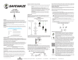
Figure 1 - Vertical Lifeline Assemblies
1202749 (3/4” polyester/polypropylene rope, 30 feet)
1202753 (5/8” polyester/polypropylene rope, 30 feet)
1202750 (3/4” polyester/polypropylene rope, 30 feet)
1202754 (5/8” polyester/polypropylene rope, 30 feet)
5901003 (3/8” wire rope, 30 feet)
Rope Cut to Length
5/8” polyester/polypropylene rope
5/8” polyester rope
3/4” polyester/polypropylene rope
3/4” polyester rope
3/8” 7x19 wire rope
User Instruction Manual
Vertical Lifelines and
Vertical Lifeline Subsystems
This manual is intended to meet the Manufacturer’s Instructions as required by ANSI Z359.1 &
CSA Z259.2.1 and should be used as part of an employee training program as required by OSHA.
WARNING: This product is part of a personal fall arrest or restraint system. The user must follow the
manufacturer’s instructions for each component of the system. These instructions must be provided to the
user of this equipment. The user must read and understand these instructions before using this equipment.
Manufacturer’s instructions must be followed for proper use and maintenance of this equipment. Alterations or
misuse of this equipment, or failure to follow instructions, may result in serious injury or death.
WARNING: IMPORTANT: If you have questions on the use, care, or suitability of this equipment for your
application, contact DBI/SALA.
WARNING: Record the product identifi cation information from the ID label in the inspection and maintenance
log in Section 10 of this manual.
Instructions for the following series products:
Vertical Lifelines
Vertical Lifeline Subsystems
(See back pages for specifi c model numbers.)
Form: 5902127 Rev: K © Copyright 2012, Capital Safety

2
DESCRIPTIONS
DBI/SALA Vertical Lifelines and Lifeline Subsystems are available in various styles and confi gurations.
Following are descriptions of typical lifelines and lifeline subsystems. Your model may not be described
exactly as confi gured:
• VERTICAL LIFELINE ASSEMBLIES:
1202749: 3/4-inch polyester/polypropylene rope, snap hook at each end, 30 feet long
1202750: 3/4-inch polyester/polypropylene rope, snap hook at one end, 30 feet long
1202753: 5/8-inch polyester/polypropylene rope, snap hook at each end, 30 feet long
1202754: 5/8-inch polyester/polypropylene rope, snap hook at one end, 30 feet long
5901003 3/8-inch 7x19 galvanized wire rope, snap hook at one end, counterweight, 30 feet long
• ROPE MATERIALS:
5/8-inch diameter, polyester/polypropylene rope
5/8-inch diameter, polyester rope
3/4-inch diameter, polyester/polypropylene rope
3/4-inch diameter polyester rope
5/16-inch diameter, 7x19 galvanized wire rope
3/8-inch diameter, 7x19 galvanized wire rope
12-mm diameter, nylon rope
12-mm diameter, polyester rope
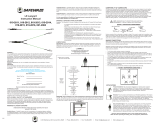
1.0 APPLICATIONS
1.1 PURPOSE: Vertical lifelines and vertical lifeline subsystems are intended to be used as part of a
personal fall arrest or restraint system. These lifelines and lifeline subsystems (with the exception
of 3/8-inch wire rope) are not designed for use in horizontal lifeline systems. Applications include:
Inspection work, construction, demolition, maintenance, oil production, confi ned space rescue,
window washing. See Figure 2.
A. FALL ARREST: The lifeline
or lifeline subsystem is
used as part of a complete
fall arrest system, which
typically includes a lifeline,
rope grab, lanyard, and full
body harness. Maximum
permissible free fall is 6 ft.
(1.8 m).
B. RESTRAINT: The lifeline or
lifeline subsystem is used as
part of a restraint system.
Restraint systems typically
include a full body harness
and a lanyard to prevent
the user from reaching a fall
hazard (leading edge roof
work). No vertical free fall
permitted.
1.2 LIMITATIONS: Consider the following application limitations before using this equipment:
A. CAPACITY: This equipment is designed for use by persons with a combined weight (person,
clothing, tools, etc.) of no more than 310 lbs (141 kg). No more than one person may be
connected to a single lifeline.
Figure 2 - Applications
Lifeline
Fall Arrest
Rope Grab
Restraint
Energy Absorbing
Lanyard
Rope Grab
Energy Absorbing
Lanyard
Lifeline

3
B. FREE FALL: Personal fall arrest systems used with these lifelines must be rigged to limit the
free fall to 6 ft. (1.8 M) (according to ANSI Z359.1). Restraint systems must be rigged such
that there is no possible vertical free fall. See subsystem manufacturer’s instructions for more
information.
C. FALL CLEARANCE: Ensure that adequate clearance exists in your fall path to prevent
striking an object. The amount of clearance required is dependent on the type of connecting
subsystem (rope grab, lanyard), the anchorage location, and the amount of stretch in the
lifeline. See subsystem manufacturer’s instructions for more information.
D. ENVIRONMENTAL HAZARDS: Use of this equipment in areas where environmental hazards
exist may require additional precautions to reduce the possibility of injury to the user or
damage to the equipment. Hazards may include, but are not limited to; high heat, caustic
chemicals, corrosive environments, high voltage power lines, explosive or toxic gases, moving
machinery, or sharp edges.
E. COMPONENT COMPATIBILITY: The lifelines must be used with DBI/SALA rope grabs only.
F. TRAINING: This equipment is intended to be used by persons trained in its correct
application and use.
1.3 APPLICABLE STANDARDS: Refer to national Standards including ANSI Z359 (.0, .1, .2, .3, and
.4) family of standards on fall protection, ANSI A10.32, CSA Z259.2.1, and applicable local, state
and federal (OSHA) requirements governing occupational safety for more information about work
positioning systems.
2.0 SYSTEM REQUIREMENTS
2.1 COMPATIBILITY OF COMPONENTS: DBI/SALA equipment is designed for use with DBI/SALA
approved components and subsystems only. Substitutions or replacements made with non-
approved components or subsystems may jeopardize compatibility of equipment and may effect
the safety and reliability of the complete system. See Table 1 for a list of lifeline materials and
the model number of compatible equipment available from DBI/SALA.
IMPORTANT: The type of lifeline used is dependent upon the application and compatibility requirements of
other system components. DBI/SALA rope grabs must be used with DBI/SALA lifelines.
Table 1 - Component Compatibility
Lifeline Material
Rope Grab Model Number
5001441 5000335 5001442 5001011 5006006 5000338 1224005
5/8” Polyester/Polypropylene X X X
3/4” Polyester/Polypropylene X
5/8” Polyester X X X
3/4” Polyester X
12 mm Nylon X
12 mm Polyester X
3/8” Wire Rope X
5/16” Wire Rope X
2.2 COMPATIBILITY OF CONNECTORS: Connectors are considered to be compatible with
connecting elements when they have been designed to work together in such a way that their
sizes and shapes do not cause their gate mechanisms to inadvertently open regardless of how
they become oriented. Contact DBI/SALA if you have any questions about compatibility.

4
Connectors (hooks, carabiners, and D-rings) must be capable of supporting at least 5,000 lbs.
(22kN). Connectors must be compatible with the anchorage or other system components. Do not
use equipment that is not compatible. Non-compatible connectors may unintentionally disengage.
See Figure 3. Connectors must be compatible in size, shape, and strength. Self locking snap
hooks and carabiners are required by ANSI Z359.1 and OSHA.
2.3 MAKING CONNECTIONS: Only use self-locking snap hooks and carabiners with this equipment.
Only use connectors that are suitable to each application. Ensure all connections are compatible
in size, shape and strength. Do not use equipment that is not compatible. Ensure all connectors
are fully closed and locked.
DBI/SALA connectors (snap hooks and carabiners) are designed to be used only as specifi ed in
each product’s user’s instructions. See Figure 4 for inappropriate connections. DBI/SALA snap
hooks and carabiners should not be connected:
A. To a D-ring to which another connector is attached.
B. In a manner that would result in a load on the gate.
NOTE: Large throat opening snap hooks should not be connected to standard size D-rings or similar objects
which will result in a load on the gate if the hook or D-ring twists or rotates. Large throat snap hooks are
designed for use on fi xed structural elements such as rebar or cross members that are not shaped in a way that
can capture the gate of the hook.
C. In a false engagement, where features that protrude from the snap hook or carabiner catch
on the anchor and without visual confi rmation seems to be fully engaged to the anchor point.
D. To each other.
E. Directly to webbing or rope lanyard or tie-back (unless the manufacturer’s instructions for
both the lanyard and connector specifi cally allow such a connection).
F. To any object which is shaped or dimensioned such that the snap hook or carabiner will not
close and lock, or that roll-out could occur.
G. In a manner that does not allow the connector to align properly while under load.
Figure 3 - Unintentional Disengagement Figure 4 - Inappropriate Connections
If the connecting element to which a snap hook (shown) or carabiner attaches
is undersized or irregular in shape, a situation could occur where the connecting
element applies a force to the gate of the snap hook or carabiner. This force may
cause the gate (of either a self-locking or a non-locking snap hook) to open,
allowing the snap hook or carabiner to disengage from the connecting point.
Small ring or other
non-compatibly
shaped element
Force is applied to the
Snap Hook.
The Gate presses against
the Connecting Ring.
The Gate opens allowing
the Snap Hook to slip off.
A. B. C. D.
E. F. G.
2.4 ANCHORAGE STRENGTH: The anchorage strength required is dependent upon the application:
A. FALL ARREST: In accordance with ANSI Z359.1, anchorages selected for fall arrest systems
shall have a strength capable of sustaining static loads applied in the directions permitted by
the system of at least:
• 5,000 pounds (22.2 kN) for non-certifi ed anchorages; or,
• Two times the maximum arresting force for certifi ed anchorages.
When more than one fall arrest systems is attached to an anchorage, the applicable strength
requirement should be modifi ed by the number of systems attached to the anchorage.

5
Per OSHA 1926.500 and 1910.66: Anchorages used for attachment of personal fall arrest
systems shall be independent of any anchorage used to support or suspend platforms and
capable of supporting at least 5,000 pounds (22.2 kN) per attached user; or, be designed,
installed, and used as part of a complete PFAS which maintains a safety factor of at least two
and is under the supervison of a qualifi ed person.
B. RESTRAINT: Anchorages selected for restraint and travel restraint systems shall have a
strength capable of sustaining static loads applied in the directions permitted by the system of
at least:
• 1,000 pounds (4.5 kN) for non-certifi ed anchorages; or,
• Two times the forseeable force for certifi ed anchorages.
When more than one fall arrest systems is attached to an anchorage, the applicable strength
requirement should be modifi ed by the number of systems attached to the anchorage.
3.0 OPERATION AND USE
WARNING: Do not alter or intentionally misuse this equipment. Consult DBI/SALA when using this equipment
in combination with components or subsystems other than those described in this manual. Some subsystem
and component combinations may interfere with the operation of this equipment. Use caution when using this
equipment around moving machinery, electrical hazards, chemical hazards, and sharp edges.
WARNING: Consult your doctor if there is reason to doubt your fi tness to safely absorb the shock from a fall
arrest. Age and fi tness seriously affect a worker’s ability to withstand falls. Pregnant women or minors must not
use DBI/SALA Vertical Lifelines or subsystems.
3.1 BEFORE EACH USE of this equipment, carefully inspect it according to steps listed in section 5.0
of this manual.
3.2 PLAN your fall arrest or restraint system before using this equipment. Consider all factors that
will affect your safety during use of this equipment. Consider the following points when planning
your system:
A. ANCHORAGE: Select a rigid anchorage point that is capable of sustaining the loads specifi ed
in section 2.3. For fall arrest applications, select anchorage locations that will minimize free
fall and swing fall hazards. For restraint applications, locate the anchorages such that no
vertical free fall is possible.
B. FREE FALL: To avoid increased free fall distance, do not work above the anchorage level. Rig
personal fall arrest systems so that the free fall is limited to 6 ft. (1.8 m) (ANSI Z359.1). Rig
restraint systems such that no vertical free fall is possible.
C. FALL ARREST FORCES: The personal fall arrest system
must limit fall arrest forces to 1,800 lbs (8 kN). and
deceleration distance must not exceed 42 in. (1 m). Do not
use a body belt for fall arrest applications.
D. SWING FALLS: See Figure 5. Swing falls occur when the
anchorage point is not directly above the point where a
fall occurs. The force of striking an object in a swing fall
may cause serious injury. Minimize swing falls by working
as directly below the anchorage point as possible. Do not
permit a swing fall if injury could occur.
Figure 5 - Swing Fall Hazard

6
E. FALL CLEARANCE: Ensure suffi cient clearance exists in your fall path to prevent striking
an object during a fall. The clearance required is dependent upon the subsystem (rope grab
and lanyard, rope grab and carabiner) and lifeline properties. Table 2 shows the approximate
elongation for new DBI/SALA lifelines in dry conditions. The elongation specifi ed is for an
applied static load of 1,800 lbs (8 kN). Wet ropes generally have more elongation than dry
ropes. Allow for additional elongation in wet or humid conditions. Lifeline elongation must be
considered when estimating fall clearance.
Table 2 - Lifeline Elongation
Lifeline Material
Lifeline Length ft. (m)
25
(7.6)
50
(15.2)
75
(22.9)
100
(30.5)
150
(45.7)
200
(61.0)
250
(76.2)
300
(91.4)
5/8” Polyester/Polypropylene 2.5 (0.8) 5 (1.5) 7.5 (2.3) 10 (3.0) 15 (4.6) 20 (6.1) 25 (7.6) 30 (9.1)
3/4” Polyester/Polypropylene 3 (0.9) 6 (1.8) 9 (2.7) 12 (3.7) 18 (5.5) 24 (7.3) 30 (9.1) 36 (11)
5/8” Polyester 2.75 (0.8) 5.5 (1.7) 8.25 (2.5) 11 (3.4) 16.5 (5.0) 22 (6.7) 27.5 (8.4) 33 (10.1)
3/4” Polyester 3.5 (1.1) 7 (2.1) 10.5 (3.2) 14 (4.3) 21 (6.4) 28 (8.5) 35 (10.7) 42 (12.8)
12 mm Nylon 6.75 (2.1) 13.5 (4.1) 20.25 (6.2) 27 (8.2) 40.5 (12.3) 54 (16.5) 67.5 (20.6) 81 (24.7)
12 mm Polyester 6.25 (1.9) 12.5 (3.8) 18.75 (5.7) 25 (7.6) 37.5 (11.4) 50 (15.2) 62.5 (19.1) 75 (22.9)
3/8” Wire Rope — — — 0.43 (0.13) 0.65 (0.2) 0.86 (0.26) 1.07 (0.33) 1.29 (0.39)
5/16” Wire Rope — — — 0.5 (0.2) 0.75 (0.23) 1 (0.3) 1.25 (0.38) 1.5 (0.45
F. SHARP EDGES: Avoid working where your lifeline, lifeline subsystem, or other system
components will be in contact with, or abrade against, unprotected sharp edges. Do not loop
a lifeline around small diameter structural members. If working with this equipment around
sharp edges is unavoidable, provide protection by using a heavy pad over the exposed sharp
edge.
G. RESCUE: The employer must have a rescue plan and the ability to implement it.
H. AFTER A FALL: Components which have been subjected to fall arrest forces must be
removed from service and destroyed.
I. GENERAL USE CONSIDERATIONS: Avoid working where your lifeline may cross or tangle
with that of another worker. Do not allow your lifeline to pass under your arms or between
your feet.
3.3 MAKING CONNECTIONS: See Figure
6. When using a hook to connect
components or to an anchorage, ensure
roll-out cannot occur. Self locking snap
hooks and carabiners should be used to
reduce the possibility of roll-out. Do not
tie a knot in the lifeline. Do not attach a
snap hook directly to a horizontal lifeline.
Follow manufacturer’s instructions for
each component of the system.
A. CONNECTING TO AN ANCHORAGE
OR ANCHORAGE CONNECTOR:
Lifelines or lifeline subsystems
supplied with connecting hooks
should be connected to the anchorage
in accordance with section 3.3.
Lifelines supplied without hooks
must have a hook or anchorage
connector spliced directly to the
lifeline. See Figure 7. Connectors
attached to synthetic rope lifelines
must be attached using a spliced
eye termination and thimble. The
Figure 6 - Making Connections
Anchorage
Carabiner
Tie-Off Adaptor
Snap Hook
Anchorage
Lifeline
Lifeline
Lifeline
Anchorage
Snap Hook

7
splice must be made with fi ve tucks.
Connectors attached to wire rope
lifelines must be attached using
a formed eye termination with a
thimble. Acceptable methods of
forming spliced eyes are: Spliced
eye with one swaged ferrule;
Return eye with a minimum of two
swaged ferrules; Return eye with a
minimum of three wire rope clips.
The connection must support 5,000
lbs (22.2 kN). Follow manufacturer’s
instructions when forming eye with
swaged ferrules or wire rope clips.
IMPORTANT: Knots must not be used for load
bearing end terminations. See ANSI Z359.1.
Some knots reduce lifeline strength fi fty percent
or more.
IMPORTANT: If the user splices or forms end terminations, proper procedures must be followed to ensure compatibility in
size, shape, and strength. DBI/SALA is not responsible for subsystems not manufactured by DBI/SALA.
B. CONNECTING ROPE GRAB TO LIFELINE: Follow the rope grab manufacturer’s instructions
for connecting the rope grab to the lifeline. DBI/SALA rope grabs must be used with these
lifelines.
3.4 AFTER USE of this equipment, clean and store according to section 6.0 of this manual.
4.0 TRAINING
4.1 It is the responsibility of the user to assure they are familiar with these instructions, and are
trained in the correct care and use of this equipment. User must also be aware of the operating
characteristics, application limits, and the consequences of improper use of this equipment.
WARNING: Training must be conducted without exposing the trainee to a fall hazard. Training should be
repeated on a periodic basis.
5.0 INSPECTION
5.1 FREQUENCY:
• Before Each Use inspect according to steps listed in section 5.2.
• This Equipment must be inspected according to steps listed in section 5.2 by a competent
person, other than the user, at least annually. Record the results of each inspection in
the inspection and maintenance log in Section 10. NOTE: Cal/OSHA requires personal fall
arrest systems be inspected prior to each use for wear, damage, and defects and inspected
by a competent person
1
at least twice a year, in accordance with the manufacturer’s
recommendations, with inspection dates documented.
WARNING: If this equipment has been subjected to fall arrest forces remove from service and destroy.
IMPORTANT: Extreme working conditions (harsh environments, prolonged use, etc.) may require increasing
the frequency of inspections.
1 Competent person: An individual knowledgeable of a manufacturer’s recommendations, instructions and manufactured components who is capable of identifying existing
and predictable hazards in the proper selection, use and maintenance of fall protection.
Figure 7 - Spliced Eye Rope Terminations
Synthetic Rope Termination
- five full tucks
Wire Rope Termination
- one swaged tucks
Wire Rope Termination
- two swaged ferules
Wire Rope Termination
- three cable clips

8
5.2 INSPECTION STEPS:
Step 1. Inspect lifeline hardware (snap hooks, ferrules, thimbles, etc.). These items must not be
damaged, broken or distorted. These items must be free of sharp edges, burrs, cracks,
worn parts, or corrosion. Hook gates must move freely and lock upon closing.
Step 2. Inspect the lifeline per the following:
SYNTHETIC ROPE: Inspect rope for concentrated wear. Material must be free of frayed
strands, broken yarns, cuts, abrasions, burns, and discoloration. The rope must be free
of knots, excessive soiling, paint build-up, and rust staining. Rope splices must be tight,
with fi ve full tucks, and thimbles must be held fi rmly by the splice. Check for chemical
or heat damage; indicated by brown, discolored, or brittle areas. Check for ultraviolet
damage; indicated by discoloration and splinters and slivers along the rope surface. All
of the above factors are known to reduce rope strength. Damaged or questionable rope
should be replaced.
WIRE ROPE: Inspect entire length of wire rope. Always wear protective gloves when
inspecting wire rope. Inspect for broken wires by passing cable through gloved hands,
fl exing the rope every few inches to expose breaks. Broken wires can be removed by
bending the wire back and forth parallel to the rope length. Do not pull broken wires
out of the rope. Replace the wire rope if there are six or more randomly distributed
broken wires in one lay; or three or more broken wires in one strand in one lay. A “lay”
of wire rope is the length of wire rope it takes for a strand (the larger group of wires) to
complete one revolution along the rope. Replace the wire rope if there are broken wires
within one inch of the swages at either end of the assembly. Wire rope should be free of
corrosion.
Step 3. Inspect labels. All labels must be present and fully legible. See Section 9.
Step 4. Inspect each system component or subsystem according to manufacturer’s instructions.
Step 5. Record the inspection date and results in the inspection log in Section 10.
5.3 If inspection reveals an unsafe or defective condition, remove equipment from service and
destroy, or contact an authorized service center for repair.
6.0 MAINTENANCE, SERVICING, STORAGE
6.1 Clean the lifeline with water and a mild detergent. Wipe hardware dry with a clean, dry cloth and
hang to air dry. Do not force dry with heat. An excessive build-up of dirt, paint, etc. may prevent
the lifeline from working properly, and in severe cases, weaken the rope.
6.2 Additional maintenance and servicing procedures must be completed by and authorized service
center. Authorization must be in writing. Do not disassemble this equipment.
6.3 Store the lifeline in a cool, dry, clean environment, out of direct sunlight. Avoid areas where
chemical vapors may be present. Thoroughly inspect the lifeline after extended storage.

9
7.0 SPECIFICATIONS
7.1 LIFELINE SPECIFICATIONS:
* The 12-mm diameter lifelines do not meet ANSI Z359.1 requirements.
Table 3 - Lifeline Specivications
Lifeline Material Tensile Strength
5/8” Diameter, Polyester/Polypropylene blend, 3-Strand Rope 7,000 lbs. (31.14 kN)
3/4” Diameter, Polyester/Polypropylene blend, 3-Strand Rope 8,820 lbs. (39.23 kN)
5/8” Diameter, Polyester, 3-Strand Rope 8,500 lbs. (37.81 kN)
3/4” Diameter, Polyester, 3-Strand Rope 12,000 lbs. (53.38 kN)
12 mm Diameter, Nylon Rope
* 6,614 lbs. (29.42 kN)
12 mm Diameter, Polyester Rope * 5,004 lbs. (22.26 kN)
3/8” Diameter, Galvanized Wire Rope 14,400 lbs. (65.05 kN)
5/16” Diameter, Galvanized Wire Rope 9,800 lbs. (43.59 kN)
5/8” Diameter, Nylon Static Kernmantle Rope 12,000 lbs. (53.38 kN)
* - 12 mm Lifelines do not meet ANSI Z359.1 requirements.
7.2 HARDWARE SPECIFICATIONS:
Snap Hook: Drop forged, alloy steel self locking snap hook, 5,000 lbs (22.2 kN). tensile
strength.
8.0 TERMINOLOGY
Authorized Person: A person assigned by the employer to perform duties at a location where
the person will be exposed to a fall hazard (otherwise referred to as “user” for the purpose of
these instructions).
Rescuer: Person or persons other than the rescue subject acting to perform an assisted rescue
by operation of a rescue system.
Certifi ed Anchorage: An anchorage for fall arrest, positioning, restraint, or rescue systems
that a qualifi ed person certifi es to be capable of supporting the potential fall forces that could
be encountered during a fall or that meet the criteria for a certifi ed anchorage prescribed in this
standard.
Qualifi ed Person: A person with a recognized degree or professional certifi cate and with
extensive knowledge, training, and experience in the fall protection and rescue fi eld who is
capable of designing, analyzing, evaluating and specifying fall protection and rescue systems to
the extent required by this standard.
Competent Person: One who is capable of identifying existing and predictable hazards in the
surroundings or working conditions which are unsanitary, hazardous, or dangerous to employees,
and who has authorization to take prompt corrective measures to eliminate them.

10
9.0 LABELING
The following labels must be present and fully legible:
9.1 ANSI Products:

11
9.2 CSA Products:

12
10.0 INSPECTION AND MAINTENANCE LOG
SERIAL NUMBER:
MODEL NUMBER:
DATE PURCHASED: DATE OF FIRST USE:
INSPECTION DATE INSPECTION ITEMS
NOTED
CORRECTIVE ACTION MAINTENANCE
PERFORMED
Approved By:
Approved By:
Approved By:
Approved By:
Approved By:
Approved By:
Approved By:
Approved By:
Approved By:
Approved By:
Approved By:
Approved By:
Approved By:
Approved By:
Approved By:
Approved By:
Approved By:
Approved By:

13
10.0 INSPECTION AND MAINTENANCE LOG
SERIAL NUMBER:
MODEL NUMBER:
DATE PURCHASED: DATE OF FIRST USE:
INSPECTION DATE INSPECTION ITEMS
NOTED
CORRECTIVE ACTION MAINTENANCE
PERFORMED
Approved By:
Approved By:
Approved By:
Approved By:
Approved By:
Approved By:
Approved By:
Approved By:
Approved By:
Approved By:
Approved By:
Approved By:
Approved By:
Approved By:
Approved By:
Approved By:
Approved By:
Approved By:

14
This instruction applies to the following models:
Additional model numbers may appear on the next printing of these instructions
1202702
1202703
1202705
1202706
1202707
1202708
1202709
1202710
1202711
1202712
1202713
1202714
1202715
1202716
1202717
1202718
1202719
1202719C
1202720
1202721
1202722
1202723
1202724
1202725
1202726
1202727
1202729
1202730
1202731
1202732
1202732C
1202733
1202733C
1202734
1202735
1202736
1202737
1202738
1202739
1202740
1202740C
1202741
1202742
1202742C
1202743
1202744
1202745
1202746
1202749
1202750
1202751
1202752
1202753
1202753C
1202754
1202754C
1202755
1202756
1202757
1202759
1202760
1202761
1202762
1202763
1202764
1202765
1202766
1202767
1202767C
1202768
1202769
1202770
1202771
1202772
1202773
1202774
1202775
1202775C
1202776
1202777
1202778
1202779
1202780
1202781
1202782
1202784
1202785
1202786
1202787
1202788
1202789
1202790
1202790C
1202791
1202792
1202793
1202794
1202794C
1202795
1202795C
1202796
1202797
1202798
1202799
1202800
1202801
1202802
1202804
1202806
1202807
1202807C
1202808
1202808C
1202809
1202810
1202811
1202812
1202813
1202814
1202815
1202816
1202817
1202818
1202819
1202820
1202821
1202821C
1202822
1202823
1202823C
1202824
1202825
1202826
1202827
1202828
1202829
1202830
1202831
1202832
1202833
1202834
1202837
1202838
1202839
1202840
1202841
1202842
1202842C
1202843
1202843C
1202844
1202844C
1202845
1202846
1202847
1202848
1202849
1202850
1202851
1202852
1202853
1202854
1202855
1202856
1202857
1202858
1202859
1202860
1202861
1202862
1202863
1202863C
1202864
1202864C
1202865
1202866
1202867
1202868
1202869
1202870
1202870C
1202871
1202872
1202873
1202874
1202876
1202877
1202878
1202878C
1202879
1202879C
1202880
1202881
1202882
1202883
1202884
1202885
1202886
1202887
1202888
1202889
1202890
1202890C
1202891
1202891C
1202892
1202892C
1202893
1202894
1202895
1202896
1202897
1202898
1202899
1202899C
1202900
1202900C
1202901
1202902
1202903
1202904
1202905
1202906
1202907
1202908
1202909
1202910
1202911
1202912
1202912C
1202913
1202914
1202915
1202915C
1202917
1202918
1202919
1202920
1202920C
1202921
1202922
1202923
1202924
1202925
1202926
1202927
1202928
1202929
1202930
1202931
1202933
1202934
1202935
1202936
1202937
1202938
1202938C
1202939
1202940
1202941
1202942
1202943
1202944
1202945
1202946
1202947
1202948
1202950
1202951
1202952
1202953
1202954
1202955
1202956
1202957
1202958
1202959
1202960
1202961
1202962
1202963
1202964
1202965
1202965C
1202966
1202967
1202968
1202969
1202970
1202971
1202972
1202973
1202974
1202976
1202977
1202978
1202979
1202980
1202981
1202982
1202983
1202984
1202984C
1202985
1202986
1202987
1202988
1202989
1202990
1202991
1202992
1202993
1202993C
1202994
1202995
1202996
1202997
1202998
1202999
1203011
1203012
1203013
1203020
1203021
1203022
1203023
1203024
1203025
1203040
1203041
1203045
1203080
1203085
1203100
1203101
1203102
1203103
1203104
1203105
1203106
1203107
1203108
1203109
1203110
1203111
1203112
1203113
1203114
1203115
1203116
1203117
1203119
1203120
1203121
1203122
1203123
1203124
1203125
1203126
1203127
1203128
1203129
1203130
1203131
1203132
1203133
1203134
1203135
1203136
1203137
1203138
1203139
1203140
1203142
1203142C
1203143
1203144
1203145
1203146
1203147
1203148
1203148C
1203149
1203150
1203151
1203152
1203153
1203154
1203155
1203156
1203157
1203158
1203159
1203160
1203161
1203162
1203163
1203164
1203165
1203166
1203167
1203169
1203170
1203171
1203172
1203173
1203174
1203175
1203176
1203177
1203178
1203179
1203180
1203181
1203182
1203183C
1203184
1203185
1203186
1203188
1203189
1203190
1203191
1203192
1203193
1203194
1203195
1203196
1203197
1203198
1203199
1203200
1203201
1204100
1210001
1210002
1210010
1210012
1210015
1210020
1210025
1210030
1210035
1210050
1210055
1210060
1210075
1210085
1210090
1210100
1210120
1210125
1210140
1210150
1210160
1210165
1210180
1210184
1210200
1210250
1210300
1210310
1210320
1210350
1210400
1210450
1210500
1210625
1210700
1210800
1210850
1211000
1211024
1211030
1211040
1211050
1211060
1211075
1211090
1211100
1211120
1211125
1211127
1211150
1211170
1211200
1211250
1211300
1211350
1211400
1211500
1211800
1211835
1212006
1212015
1212025
1212027
1212030
1212040
1212050
1212070
1212075
1212080
1212100
1212120
1212125
1212150
1212180
1212200
1212210
1212300
1212400
1212500
1212610
1212611
1212612
1212613
1212614
1212615
1213300
1237800
3401000
3511000
3511001
3511002
3511003
3511004
3511005
3511006
3511007
3511008
3511009
3511010
3511011
3511012
3511013
3511014
3511015
3511016
3511017
3511018
3511019
3511022
3511023
3511024
3900071
3900085
4195155
5900110
5900111
5900112
5900113
5900114
5900115
5900116
5900117
5900118
5900119
5900120
5900121
5900122
5900124
5900125
5900126
5900127
5900128
5900129
5900130
5900131
5900132
5900133
5900134
5900135
5900137
5900138
5900139
5900152
5900153
5900154
5900155
5900156
5900160
5900161
5900162
5900163
5900164
5900165
5900166
5900167
5900168
5901000
5901001
5901002
5901003
5901004
5901005
5901006
5901007
5901008
5901009
5901010
5901011
5901012
5901013
5901014
5901015
5901016
5901018
5901019
5901020
5901021
5901022
5901023
5901024
5901025
5901026
5901027
5901028
5901029
5901030
5901031
5901032
5901033
5901034
5901035
5901037
5901038
5901039
6126012
6126023
6126025
6126050
6126060
6126090
6126100
6126113
6126165
6126175
6126196
6126200
6126248
6130004
6130005
6130010
6130011
6130012
6130013
6130014
6130015
6130016
6130018
6130019
6130020
6130022
6130024
6130025
6130026
6130029
6130030
6130031
6130032
6130033
6130034
6130036
6130037
6130038
6130040
6130041
6130044
6130045
6130050
6130054
6130055
6130060
6130064
6130066
6130070
6130074
6130075
6130080
6130082
6130085
6130090
6130093
6130095
6130100
6130105
6130109
6130110
6130114
6130115
6130120
6130125
6130130
6130131
6130140
6130142
6130144
6130145
6130147
6130150
6130154
6130160
6130164
6130165
6130170
6130175
6130180
6130184
6130185
6130196
6130200
6130220
6130225
6130230
6130240
6130245
6130250
6130275
6130280
6130300
6130330
6130340
6130350
6130375
6130400
6130427
6130450
6130454
6130500

15
This instruction applies to the following models:
Additional model numbers may appear on the next printing of these instructions
6130550
6130600
6130700
6130730
6130760
6130850
6130900
6131000
6131200
6132000
6133200
6140007
6140008
6140009
6140010
6140011
6140012
6140013
6140014
6140015
6140016
6140017
6140018
6140019
6140020
6140021
6140022
6140023
6140024
6140025
6140026
6140027
6140028
6140029
6140030
6140031
6140032
6140033
6140034
6140035
6140036
6140037
6140038
6140039
6140040
6140041
6140042
6140044
6140046
6140049
6140050
6140051
6140052
6140055
6140059
6140060
6140065
6140070
6140074
6140075
6140077
6140079
6140080
6140085
6140086
6140088
6140090
6140094
6140095
6140097
6140099
6140100
6140102
6140104
6140105
6140108
6140109
6140111
6140113
6140114
6140115
6140117
6140120
6140121
6140122
6140123
6140125
6140128
6140129
6140130
6140131
6140134
6140136
6140138
6140139
6140140
6140143
6140144
6140146
6140150
6140151
6140152
6140160
6140166
6140174
6140175
6140180
6140184
6140190
6140200
6140204
6140220
6140226
6140228
6140230
6140250
6140300
6140310
6140328
6140333
6140350
6140364
6140375
6140396
6140400
6140411
6140440
6140450
6140500
6140506
6140510
6140535
6140550
6140560
6140600
6140603
6140650
6140674
6140700
6140720
6140750
6140788
6140800
6140820
6140850
6140875
6140900
6140930
6141000
6141200
6141209
6141221
6141300
6141420
6141450
6141480
6141600
6141650
6141700
6141730
6141742
6141800
6141965
6142000
6142030
6142300
6142400
6142720
6142800

LIMITED LIFETIME WARRANTY
Warranty to End User: D B Industries, Inc., dba CAPITAL SAFETY USA (“CAPITAL SAFETY”) warrants to the
original end user (“End User”) that its products are free from defects in materials and workmanship under
normal use and service. This warranty extends for the lifetime of the product from the date the product is
purchased by the End User, in new and unused condition, from a CAPITAL SAFETY authorized distributor.
CAPITAL SAFETY’S entire liability to End User and End User’s exclusive remedy under this warranty is limited
to the repair or replacement in kind of any defective product within its lifetime (as CAPITAL SAFETY in its sole
discretion determines and deems appropriate). No oral or written information or advice given by CAPITAL
SAFETY, its distributors, directors, offi cers, agents or employees shall create any different or additional
warranties or in any way increase the scope of this warranty. CAPITAL SAFETY will not accept liability for defects
that are the result of product abuse, misuse, alteration or modifi cation, or for defects that are due to a failure to
install, maintain, or use the product in accordance with the manufacturer’s instructions.
CAPITAL SAFETY’S WARRANTY APPLIES ONLY TO THE END USER. THIS WARRANTY IS THE ONLY WARRANTY
APPLICABLE TO OUR PRODUCTS AND IS IN LIEU OF ALL OTHER WARRANTIES AND LIABILITIES, EXPRESSED
OR IMPLIED. CAPITAL SAFETY EXPRESSLY EXCLUDES AND DISCLAIMS ANY IMPLIED WARRANTIES OF
MERCHANTABILITY OR FITNESS FOR A PARTICULAR PURPOSE, AND SHALL NOT BE LIABLE FOR INCIDENTAL,
PUNITIVE OR CONSEQUENTIAL DAMAGES OF ANY NATURE, INCLUDING WITHOUT LIMITATION, LOST PROFITS,
REVENUES, OR PRODUCTIVITY, OR FOR BODILY INJURY OR DEATH OR LOSS OR DAMAGE TO PROPERTY, UNDER
ANY THEORY OF LIABILITY, INCLUDING WITHOUT LIMITATION, CONTRACT, WARRANTY, STRICT LIABILITY, TORT
(INCLUDING NEGLIGENCE) OR OTHER LEGAL OR EQUITABLE THEORY.
Certificate No. FM 39709
ISO
9001
The Ultimate in Fall Protection
CSG USA & Latin America
3833 SALA Way
Red Wing, MN 55066-5005
Toll Free: 800.328.6146
Phone: 651.388.8282
Fax: 651.388.5065
solutions@capitalsafety.com
CSG Canada
260 Export Boulevard
Mississauga, ON L5S 1Y9
Phone: 905.795.9333
Toll-Free: 800.387.7484
Fax: 888.387.7484
info.ca@capitalsafety.com
CSG Northern Europe
5a Merse Road
North Moons, Moat
Reditch, Worcestershire, UK
B98 9HL
Phone: + 44 (0)1527 548 000
Fax: + 44 (0)1527 591 000
csgne@capitalsafety.com
CSG EMEA
(Europe, Middle East, Africa)
Le Broc Center
Z.I. 1ère Avenue
5600 M B.P. 15 06511
Carros
Le Broc Cedex
France
Phone: + 33 4 97 10 00 10
Fax: + 33 4 93 08 79 70
information@capitalsafety.com
CSG Australia & New Zealand
95 Derby Street
Silverwater
Sydney NSW 2128
AUSTRALIA
Phone: +(61) 2 8753 7600
Toll-Free : 1 800 245 002 (AUS)
Toll-Free : 0800 212 505 (NZ)
Fax: +(61) 2 87853 7603
sales@capitalsafety.com.au
CSG Asia
Singapore:
16S, Enterprise Road
Singapore 627666
Phone: +65 - 65587758
Fax: +65 - 65587058
inquiry@capitalsafety.com
Shanghai:
Rm 1406, China Venturetech Plaza
819 Nan Jing Xi Rd,
Shanghai 200041, P R China
Phone: +86 21 62539050
Fax: +86 21 62539060
www.capitalsafety.com

GARANTÍA LIMITADA DE POR VIDA
Garantía para el usuario fi nal: D B Industries, Inc., que opera bajo el nombre de CAPITAL SAFETY USA (“CAPITAL
SAFETY”) garantiza al usuario fi nal original (“Usuario fi nal”) que sus productos están libres de defectos de materiales
y de mano de obra en condiciones normales de uso y mantenimiento. Esta garantía se extiende durante la vida útil del
producto a partir de la fecha en que el Usuario fi nal adquiere el producto, nuevo y sin uso, a un distribuidor autorizado
de CAPITAL SAFETY. La entera responsabilidad de CAPITAL SAFETY hacia el Usuario fi nal y el remedio exclusivo para
el Usuario fi nal bajo esta garantía están limitados a la reparación o el reemplazo por materiales de todo producto
defectuoso dentro de su vida útil (según CAPITAL SAFETY lo determine y considere apropiado a su solo criterio).
Ninguna información o asesoramiento, oral o escrito, proporcionado por CAPITAL SAFETY, sus distribuidores, directores,
funcionarios, agentes o empleados creará una garantía diferente o adicional ni aumentará de ninguna manera el
alcance de esta garantía. CAPITAL SAFETY no aceptará responsabilidad por defectos resultantes del abuso, el uso
incorrecto, la alteración o la modifi cación del producto, ni por defectos resultantes de no respetar las instrucciones del
fabricante durante la instalación, el mantenimiento o el uso del producto.
LA GARANTÍA DE CAPITAL SAFETY SE APLICA ÚNICAMENTE AL USUARIO FINAL. ESTA GARANTÍA ES LA ÚNICA
GARANTÍA QUE SE APLICA A NUESTROS PRODUCTOS Y REEMPLAZA A TODAS LAS OTRAS GARANTÍAS Y
RESPONSABILIDADES, EXPRESAS O IMPLÍCITAS. CAPITAL SAFETY EXPRESAMENTE EXCLUYE Y RENUNCIA A TODAS
LAS GARANTÍAS IMPLÍCITAS DE COMERCIABILIDAD O APTITUD PARA UN PROPÓSITO PARTICULAR, Y NO SERÁ
RESPONSABLE POR DAÑOS INCIDENTALES, PUNITIVOS O EMERGENTES DE NINGUNA NATURALEZA, INCLUYENDO SIN
LIMITACIÓN PÉRDIDAS DE INGRESOS, GANANCIAS O PRODUCTIVIDAD; NI POR LESIONES CORPORALES O MUERTE,
O PÉRDIDA DE O DAÑO A LA PROPIEDAD, BAJO CUALQUIER TEORÍA DE RESPONSABILIDAD, INCLUYENDO SIN
LIMITACIÓN CONTRATO, GARANTÍA, RESPONSABILIDAD ESTRICTA, AGRAVIO (INCLUIDA NEGLIGENCIA) O CUALQUIER
OTRA TEORÍA LEGAL O EQUITATIVA.
Certificate No. FM 39709
ISO
9001
CSG EE. UU. y Latinoamérica
3833 SALA Way
Red Wing, MN 55066-5005
Llamada gratis: 800.328.6146
Tel.: 651.388.8282
Fax: 651.388.5065
solutions@capitalsafety.com
CSG Canadá
260 Export Boulevard
Mississauga, ON L5S 1Y9
Tel.: 905.795.9333
Llamada gratis: 800.387.7484
Fax: 888.387.7484
info.ca@capitalsafety.com
CSG Europa Septentrional
5a Merse Road
North Moons, Moat
Reditch, Worcestershire, UK
B98 9HL
Phone: + 44 (0)1527 548 000
Fax: + 44 (0)1527 591 000
csgne@capitalsafety.com
CSG EMEA
(Europa, Oriente Medio, África)
Le Broc Center
Z.I. 1ère Avenue
5600 M B.P. 15 06511
Carros
Le Broc Cedex
Francia
Tel.: + 33 4 97 10 00 10
Fax: + 33 4 93 08 79 70
information@capitalsafety.com
CSG Australia y Nueva Zelanda
95 Derby Street
Silverwater
Sidney, NSW 2128
AUSTRALIA
Tel.: +(61) 2 8753 7600
Llamada gratis: 1 800 245 002 (AUS)
Llamada gratis: 0800 212 505 (NZ)
Fax: +(61) 2 8753 7600
sales@capitalsafety.com.au
CSG Asia
Singapur:
16S, Enterprise Road
Singapur 627666
Tel.: +65 - 65587758
Fax: +65 - 65587058
inquiry@capitalsafety.com
Shanghai:
Rm 1406, China Venturetech Plaza
819 Nan Jing Xi Rd,
Shanghai 200041, Repúblic
Popular China
Tel.: +86 21 62539050
Fax: +86 21 62539060
www.capitalsafety.com
The Ultimate in Fall Protection

15
6130550
6130600
6130700
6130730
6130760
6130850
6130900
6131000
6131200
6132000
6133200
6140007
6140008
6140009
6140010
6140011
6140012
6140013
6140014
6140015
6140016
6140017
6140018
6140019
6140020
6140021
6140022
6140023
6140024
6140025
6140026
6140027
6140028
6140029
6140030
6140031
6140032
6140033
6140034
6140035
6140036
6140037
6140038
6140039
6140040
6140041
6140042
6140044
6140046
6140049
6140050
6140051
6140052
6140055
6140059
6140060
6140065
6140070
6140074
6140075
6140077
6140079
6140080
6140085
6140086
6140088
6140090
6140094
6140095
6140097
6140099
6140100
6140102
6140104
6140105
6140108
6140109
6140111
6140113
6140114
6140115
6140117
6140120
6140121
6140122
6140123
6140125
6140128
6140129
6140130
6140131
6140134
6140136
6140138
6140139
6140140
6140143
6140144
6140146
6140150
6140151
6140152
6140160
6140166
6140174
6140175
6140180
6140184
6140190
6140200
6140204
6140220
6140226
6140228
6140230
6140250
6140300
6140310
6140328
6140333
6140350
6140364
6140375
6140396
6140400
6140411
6140440
6140450
6140500
6140506
6140510
6140535
6140550
6140560
6140600
6140603
6140650
6140674
6140700
6140720
6140750
6140788
6140800
6140820
6140850
6140875
6140900
6140930
6141000
6141200
6141209
6141221
6141300
6141420
6141450
6141480
6141600
6141650
6141700
6141730
6141742
6141800
6141965
6142000
6142030
6142300
6142400
6142720
6142800
Estas instrucciones se aplican a los siguientes modelos:
Es posible que aparezcan números de modelo adicionales en la próxima edición de estas instrucciones.

14
1202702
1202703
1202705
1202706
1202707
1202708
1202709
1202710
1202711
1202712
1202713
1202714
1202715
1202716
1202717
1202718
1202719
1202719C
1202720
1202721
1202722
1202723
1202724
1202725
1202726
1202727
1202729
1202730
1202731
1202732
1202732C
1202733
1202733C
1202734
1202735
1202736
1202737
1202738
1202739
1202740
1202740C
1202741
1202742
1202742C
1202743
1202744
1202745
1202746
1202749
1202750
1202751
1202752
1202753
1202753C
1202754
1202754C
1202755
1202756
1202757
1202759
1202760
1202761
1202762
1202763
1202764
1202765
1202766
1202767
1202767C
1202768
1202769
1202770
1202771
1202772
1202773
1202774
1202775
1202775C
1202776
1202777
1202778
1202779
1202780
1202781
1202782
1202784
1202785
1202786
1202787
1202788
1202789
1202790
1202790C
1202791
1202792
1202793
1202794
1202794C
1202795
1202795C
1202796
1202797
1202798
1202799
1202800
1202801
1202802
1202804
1202806
1202807
1202807C
1202808
1202808C
1202809
1202810
1202811
1202812
1202813
1202814
1202815
1202816
1202817
1202818
1202819
1202820
1202821
1202821C
1202822
1202823
1202823C
1202824
1202825
1202826
1202827
1202828
1202829
1202830
1202831
1202832
1202833
1202834
1202837
1202838
1202839
1202840
1202841
1202842
1202842C
1202843
1202843C
1202844
1202844C
1202845
1202846
1202847
1202848
1202849
1202850
1202851
1202852
1202853
1202854
1202855
1202856
1202857
1202858
1202859
1202860
1202861
1202862
1202863
1202863C
1202864
1202864C
1202865
1202866
1202867
1202868
1202869
1202870
1202870C
1202871
1202872
1202873
1202874
1202876
1202877
1202878
1202878C
1202879
1202879C
1202880
1202881
1202882
1202883
1202884
1202885
1202886
1202887
1202888
1202889
1202890
1202890C
1202891
1202891C
1202892
1202892C
1202893
1202894
1202895
1202896
1202897
1202898
1202899
1202899C
1202900
1202900C
1202901
1202902
1202903
1202904
1202905
1202906
1202907
1202908
1202909
1202910
1202911
1202912
1202912C
1202913
1202914
1202915
1202915C
1202917
1202918
1202919
1202920
1202920C
1202921
1202922
1202923
1202924
1202925
1202926
1202927
1202928
1202929
1202930
1202931
1202933
1202934
1202935
1202936
1202937
1202938
1202938C
1202939
1202940
1202941
1202942
1202943
1202944
1202945
1202946
1202947
1202948
1202950
1202951
1202952
1202953
1202954
1202955
1202956
1202957
1202958
1202959
1202960
1202961
1202962
1202963
1202964
1202965
1202965C
1202966
1202967
1202968
1202969
1202970
1202971
1202972
1202973
1202974
1202976
1202977
1202978
1202979
1202980
1202981
1202982
1202983
1202984
1202984C
1202985
1202986
1202987
1202988
1202989
1202990
1202991
1202992
1202993
1202993C
1202994
1202995
1202996
1202997
1202998
1202999
1203011
1203012
1203013
1203020
1203021
1203022
1203023
1203024
1203025
1203040
1203041
1203045
1203080
1203085
1203100
1203101
1203102
1203103
1203104
1203105
1203106
1203107
1203108
1203109
1203110
1203111
1203112
1203113
1203114
1203115
1203116
1203117
1203119
1203120
1203121
1203122
1203123
1203124
1203125
1203126
1203127
1203128
1203129
1203130
1203131
1203132
1203133
1203134
1203135
1203136
1203137
1203138
1203139
1203140
1203142
1203142C
1203143
1203144
1203145
1203146
1203147
1203148
1203148C
1203149
1203150
1203151
1203152
1203153
1203154
1203155
1203156
1203157
1203158
1203159
1203160
1203161
1203162
1203163
1203164
1203165
1203166
1203167
1203169
1203170
1203171
1203172
1203173
1203174
1203175
1203176
1203177
1203178
1203179
1203180
1203181
1203182
1203183C
1203184
1203185
1203186
1203188
1203189
1203190
1203191
1203192
1203193
1203194
1203195
1203196
1203197
1203198
1203199
1203200
1203201
1204100
1210001
1210002
1210010
1210012
1210015
1210020
1210025
1210030
1210035
1210050
1210055
1210060
1210075
1210085
1210090
1210100
1210120
1210125
1210140
1210150
1210160
1210165
1210180
1210184
1210200
1210250
1210300
1210310
1210320
1210350
1210400
1210450
1210500
1210625
1210700
1210800
1210850
1211000
1211024
1211030
1211040
1211050
1211060
1211075
1211090
1211100
1211120
1211125
1211127
1211150
1211170
1211200
1211250
1211300
1211350
1211400
1211500
1211800
1211835
1212006
1212015
1212025
1212027
1212030
1212040
1212050
1212070
1212075
1212080
1212100
1212120
1212125
1212150
1212180
1212200
1212210
1212300
1212400
1212500
1212610
1212611
1212612
1212613
1212614
1212615
1213300
1237800
3401000
3511000
3511001
3511002
3511003
3511004
3511005
3511006
3511007
3511008
3511009
3511010
3511011
3511012
3511013
3511014
3511015
3511016
3511017
3511018
3511019
3511022
3511023
3511024
3900071
3900085
4195155
5900110
5900111
5900112
5900113
5900114
5900115
5900116
5900117
5900118
5900119
5900120
5900121
5900122
5900124
5900125
5900126
5900127
5900128
5900129
5900130
5900131
5900132
5900133
5900134
5900135
5900137
5900138
5900139
5900152
5900153
5900154
5900155
5900156
5900160
5900161
5900162
5900163
5900164
5900165
5900166
5900167
5900168
5901000
5901001
5901002
5901003
5901004
5901005
5901006
5901007
5901008
5901009
5901010
5901011
5901012
5901013
5901014
5901015
5901016
5901018
5901019
5901020
5901021
5901022
5901023
5901024
5901025
5901026
5901027
5901028
5901029
5901030
5901031
5901032
5901033
5901034
5901035
5901037
5901038
5901039
6126012
6126023
6126025
6126050
6126060
6126090
6126100
6126113
6126165
6126175
6126196
6126200
6126248
6130004
6130005
6130010
6130011
6130012
6130013
6130014
6130015
6130016
6130018
6130019
6130020
6130022
6130024
6130025
6130026
6130029
6130030
6130031
6130032
6130033
6130034
6130036
6130037
6130038
6130040
6130041
6130044
6130045
6130050
6130054
6130055
6130060
6130064
6130066
6130070
6130074
6130075
6130080
6130082
6130085
6130090
6130093
6130095
6130100
6130105
6130109
6130110
6130114
6130115
6130120
6130125
6130130
6130131
6130140
6130142
6130144
6130145
6130147
6130150
6130154
6130160
6130164
6130165
6130170
6130175
6130180
6130184
6130185
6130196
6130200
6130220
6130225
6130230
6130240
6130245
6130250
6130275
6130280
6130300
6130330
6130340
6130350
6130375
6130400
6130427
6130450
6130454
6130500
Estas instrucciones se aplican a los siguientes modelos:
Es posible que aparezcan números de modelo adicionales en la próxima edición de estas instrucciones.

13
10.0 REGISTRO DE INSPECCIÓN Y MANTENIMIENTO
NÚMERO DE SERIE:
NÚMERO DE MODELO:
FECHA DE COMPRA: FECHA DE PRIMER USO:
FECHA DE INSPECCIÓN OBSERVACIONES DE LA
INSPECCIÓN
MEDIDAS
CORRECTIVAS
MANTENIMIENTO
REALIZADO
Aprobado por:
Aprobado por:
Aprobado por:
Aprobado por:
Aprobado por:
Aprobado por:
Aprobado por:
Aprobado por:
Aprobado por:
Aprobado por:
Aprobado por:
Aprobado por:
Aprobado por:
Aprobado por:
Aprobado por:
Aprobado por:
Aprobado por:
Aprobado por:
/