Simply VO-115RM-SP User manual

Type
User manual

Simply VO-115RM-SP is an emergency light with a long-lasting Ni-cad battery that provides 3+ hours of illumination during power outages. It features a bright LED light source with a color temperature of 6500K, providing a cool white light. The light can be rotated from 0 to 180 degrees, making it suitable for various applications. Installation options include ceiling mount, wall mount, and wall side mount, allowing for easy placement in different locations.

Simply VO-115RM-SP is an emergency light with a long-lasting Ni-cad battery that provides 3+ hours of illumination during power outages. It features a bright LED light source with a color temperature of 6500K, providing a cool white light. The light can be rotated from 0 to 180 degrees, making it suitable for various applications. Installation options include ceiling mount, wall mount, and wall side mount, allowing for easy placement in different locations.

IMPORTANT SAFEGUARDS
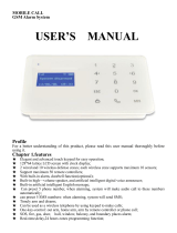
WIRING DIAGRAM
READ AND FOLLOW ALL SAFETY INSTRUCTIONS
Blac k Wire (L)
White Wire (N)
Transformer
For batter y
Battery
Input AC cabl e
MAIN PCBA
Test
red le d
LED Stri p
AC WIRING
CIRCUITRY
• Emergency duration: ≥ 3 hours
• Recharge time: 24 hours
• Output Wattage: 1.5W
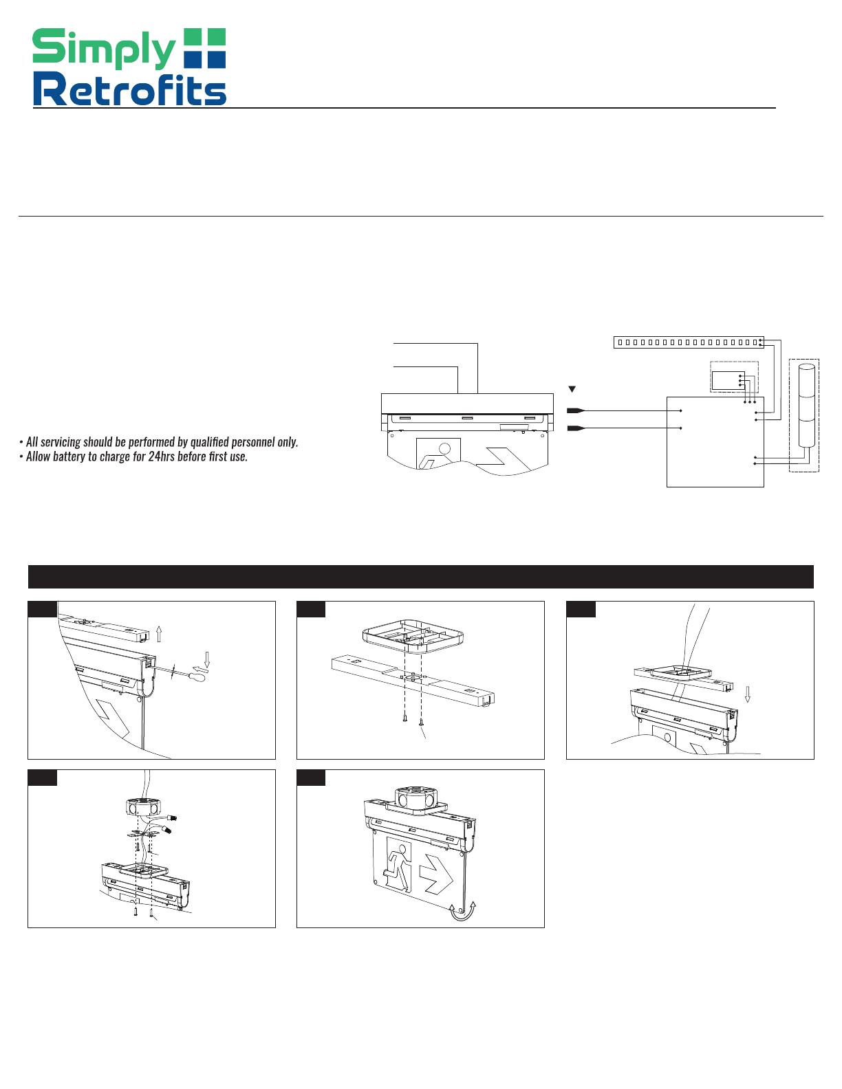
Fig 1 Fig 2 Fig 3
Fig 4 Fig 5
• Light Source: Ultra bright LED
• Color temperature: 6500K
• Ni-cad Battery: 3.6V 900mAh
Insert the flat screw driver
into the buckle groove and
remove the top cover
The flat screw driver should be
no more than 3mm in size
3mm
M4x25mm screw
M4x20mm screw
ST 2.9x9.5mm screws
CEILING MOUNT
AC WIRING
Working Voltage:
AC120V - 347V 50 60Hz
Black Wire (L)
White Wire (N)
--------------------
Green Wire (E)
AC WIRING
Black Wire (L)
AC120V -347V
Whit e Wire (N)
TEST
AC ON TEST
AC ON TEST
AC ON TEST
AC ON TEST
Snap together
VO-115RM-SP
Slim Running Man Emergency Light
• Review the diagrams thoroughly before beginning.
• All electrical connections must be in accordance with local codes,
ordinances and the National Electric Code.
• Disconnect power at fuse or circuit breaker before installing
or servicing.
• Do not use outdoors.
• Do not mount in hazardous locations or near gas or electric heaters.
• Do not let power cords touch hot surfaces.
• Equipment should be mounted in locations and at heights where
it will not be subject to tampering by unauthorized personnel.
• The use of accessory equipment is not recommended by
the manufacturer.
• Do not use this equipment other than intended use.
1. Remove the top cover using flat driving(Fig1)
2. Connected the top cover with the canopy using the screws(Supplied) .(Fig2)
3. Feed AC supply wire through top cover and canopy center hole,snap top cover
and the fixture together.(Fig3)
4. Assemble canopy onto Junction box with screws (supplied) and make proper
wire connections.
Black Wire (L); White Wire (N);(Fig4
5. Use screws (supplied) to tighten canopy to mounting plate
(spider plate/cross bar)(Fig5)
6. The unit can be installed on any surface, you may rotate the
Acrylic panel in any angle from 0 degrees to 180 degrees.(Fig5)
www.simplyretrofits.com
Fig 1 Fig 2 Fig 3
Fig 4 Fig 5
Fig 1 Fig 2 Fig 3
Fig 1 Fig 2 Fig 3
Fig 4 Fig 5
Insert the flat screw driver
into the buckle groove and
remove the top cover
The flat screw driver should be
no more than 3mm in size
3mm
Insert the flat screw driver
into the buckle groove and
remove the top cover
The flat screw driver should be
no more than 3mm in size
3mm
Press the tab with
flat screw driver
Snap together
M4x25mm screw
M4x20mm screw
M4x25mm screw
M4x20mm screw
ST 2.9x9.5mm screws
ST 2.9x16mm screws
Button up the top
1. Remove the top cover using flat driving(Fig1)
2. Connected the top cover with the canopy using the screws
(Supplied) .(Fig2)
3. Feed AC supply wire through top cover and canopy center hole,
snap top cover and the fixture together.(Fig3)
4. Assemble canopy onto Junction box with screws (supplied) and make
proper wire connections.Black Wire (L); White Wire (N);(Fig4)
5. Use screws (supplied) to tighten canopy to mounting plate (spider
plate/cross bar)(Fig5)
6. The unit can be installed on any surface, you may rotate the
Acrylic panel in any angle from 0 degrees to 180 degrees.(Fig5)
1. Remove the top cover scerw driver and remove the end cap.
using a flat screw Pull out the wires through the side.(Fig1)
2. Snap the top cover into the fixture.(Fig2)
3. Pullout all AC supply wires and feed the wires through the holes of
end cap and then canopy.(Fig3)
4. Assemble canopy and end cap to metal bracket with screws (supplied)
and make proper wire connections.(Fig4)
5. Using screws (supplied) tighten canopy to spider plate (crossbar).
(Fig5)
6. The unit can be installed on any surface, you may rotate the
+Acrylic panel in any angle from 0 degree to 180 degree. (Fig1)
1. Remove the button(Fig1.Fig2)
2. Change to desired pictogram(Fig3)
3. Reinstall buttons and snap them together together(Fig4)
AC ON TEST
AC ON TEST
AC ON TEST
AC ON TEST
WALL SIDE MOUNT
CHANGING OR REPLACING PICTOGRAM
WALL MOUNT
AC ON TEST
AC ON TEST
AC ON TEST
AC ON TEST
Fig 4
www.simplyretrofits.com
  • Page 1 1
  • Page 2 2

Simply VO-115RM-SP User manual

Type
User manual

Simply VO-115RM-SP is an emergency light with a long-lasting Ni-cad battery that provides 3+ hours of illumination during power outages. It features a bright LED light source with a color temperature of 6500K, providing a cool white light. The light can be rotated from 0 to 180 degrees, making it suitable for various applications. Installation options include ceiling mount, wall mount, and wall side mount, allowing for easy placement in different locations.

Ask a question and I''ll find the answer in the document

Finding information in a document is now easier with AI