Cumberland 12', 15', 18' and 21' Bulk Feed Tank Series and Grain Hopper Tank Series Owner's manual
- Type
- Owner's manual

PNEG-1461
12', 15', 18' and 21' Bulk Feed
Tank Series and Grain Hopper
Tank Series
Assembly Manual
PNEG-1461
Version: 4.1
Date: 02-24-16

2 PNEG-1461 12', 15', 18' and 21' Bulk Feed Tank Series and Grain Hopper Tank Series
All information, illustrations, photos and specifications in this manual are based on the latest
information available at the time of publication. The right is reserved to make changes at any
time without notice.

Table of Contents
PNEG-1461 12', 15', 18' and 21' Bulk Feed Tank Series and Grain Hopper Tank Series 3
Contents
Chapter 1 Introduction ..........................................................................................................................................5
Proper Storage of Grain Bin/Silo Materials Prior to Construction ......................................................... 5
Chapter 2 Safety .....................................................................................................................................................6
Safety Guidelines .................................................................................................................................. 6
Cautionary Symbols Definitions ............................................................................................................ 7
Safety Cautions ..................................................................................................................................... 8
Safety Sign-Off Sheet ......................................................................................................................... 11
Chapter 3 Safety Decals ......................................................................................................................................12
Chapter 4 General Information ...........................................................................................................................13
Bulk Feed Tank Assembly Manual General Instructions .................................................................... 13
Chapter 5 Foundation ..........................................................................................................................................15
Chapter 6 Sidewall Assembly .............................................................................................................................26
Bulk Feed Tank Assembly .................................................................................................................. 26
12' Sidewall Sheet Orientation ............................................................................................................ 27
Sidewall Erection ................................................................................................................................. 28
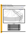
Chapter 7 Roof .....................................................................................................................................................32
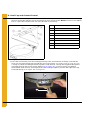
12'-18' BFT Sealed Roof Panel Installation ......................................................................................... 32
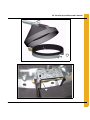
Peak Ring Collar to Roof Panels ......................................................................................................... 33
12' Roof Reinforcement Angle ............................................................................................................ 34
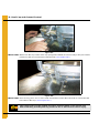
15' and 18' Roof Assembly Instructions .............................................................................................. 35
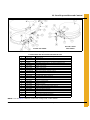
Raising the Roof .................................................................................................................................. 38
Chapter 8 Optional BFT Ladder Assembly ........................................................................................................40
Starter Bracket Installation .................................................................................................................. 41
Sidewall and Roof Ladder Installation ................................................................................................. 42
Roof Ladder Support Bracket Installation ........................................................................................... 43
Ladder Standoff Installation ................................................................................................................ 49
Ladder Section Assembly ................................................................................................................... 50
Ladder Support Detail ......................................................................................................................... 51
Ladder Decal Application .................................................................................................................... 51
Chapter 9 Ladder Handrails ................................................................................................................................52
Handrail Installation for Ladder System without Safety Cage ............................................................. 52
Chapter 10 Safety Cage .......................................................................................................................................60
Ladder System with Safety Cage ...................................................................................................... 60
Safety Cage Hoop Assembly ............................................................................................................. 62
Safety Cage Installation ..................................................................................................................... 64
Chapter 11 Roof Cap and Ground Control ........................................................................................................67
Roof Cap and Ground Control Instructions ....................................................................................... 67
Roof Cap ........................................................................................................................................... 74
Chapter 12 Hopper Assembly .............................................................................................................................76
Installing the 15' Diameter 60° Hopper Bin Assembly ....................................................................... 76
18' Diameter 45° and 21' Diameter 45° Hopper Bin Assembly .......................................................... 82
Hopper Collar Assembly .................................................................................................................... 85

Table of Contents
4 PNEG-1461 12', 15', 18' and 21' Bulk Feed Tank Series and Grain Hopper Tank Series
Chapter 13 Legs and Leg Bracing ......................................................................................................................87
12' Only .............................................................................................................................................. 87
Installation of Leg to Sidewall ............................................................................................................ 88
Installation of Leg to Sidewall for 15', 18' and 21' BFT ...................................................................... 89
12'-21' Leg Bracing ............................................................................................................................ 90
Bracing Hole Layouts ........................................................................................................................ 92
Hopper to Leg Bracing for 12', 18' and 21' ........................................................................................ 96
Hopper to Leg Bracing for 15' ............................................................................................................ 97
Chapter 14 Raising Bin ........................................................................................................................................98
Raising Bin to Set on Foundation ...................................................................................................... 98
Standard Hopper Bin Anchoring ........................................................................................................ 98
Anchoring Tank ................................................................................................................................. 99
Bin Grounding Instructions .............................................................................................................. 100
Chapter 15 Pneumatic Fill Kit ...........................................................................................................................101
Pneumatic Fill Kit Assembly ............................................................................................................ 101
Roof Panel ....................................................................................................................................... 102
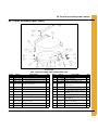
Chapter 16 Parts List .........................................................................................................................................103
12' Diameter 60° Hopper Bin Specifications .................................................................................... 104
12' Diameter 60° Hopper Bin Hardware Specifications ................................................................... 106
12' Diameter 45° Hopper Bin Specifications .................................................................................... 108
12' Diameter 45° Hopper Bin Hardware Specifications ................................................................... 110
15' Diameter 60° Hopper Bin Specifications .................................................................................... 112
15' Diameter 60° Hopper Bin Hardware Specifications ................................................................... 114
15' Diameter 45° Hopper Bin Specifications .................................................................................... 116
15' Diameter 45° Hopper Bin Hardware Specifications ................................................................... 118
18' Diameter 45° Hopper Bin Specifications .................................................................................... 120
18' Diameter 45° Hopper Bin Hardware Specifications ................................................................... 122
21' Diameter 45° Hopper Bin Specifications .................................................................................... 124
21' Diameter 45° Hopper Bin Hardware Specifications ................................................................... 126
Chapter 17 Warranty ..........................................................................................................................................129

PNEG-1461 12', 15', 18' and 21' Bulk Feed Tank Series and Grain Hopper Tank Series 5
1. Introduction
READ THIS MANUAL carefully to learn how to properly use and install equipment. Failure to do so could
result in personal injury or equipment damage.
INSPECT the shipment immediately upon arrival. The customer is responsible for ensuring that all
quantities are correct. The customer should report and note any damage or shortage on the bill of
lading to justify their claim to the transport company.
THIS MANUAL SHOULD BE CONSIDERED a permanent part of your equipment and should be easily
accessible when needed.
This warranty provides you the assurance that the company will back its products when defects appear
within the warranty period. In some circumstances, the company also provides field improvements, often
without charge to the customer, even if the product is out of warranty. Should the equipment be abused,
or modified to change its performance beyond the factory specifications, the warranty will become void
and field improvements may be denied.
Proper Storage of Grain Bin/Silo Materials Prior to Construction
Wet storage stain (rust) will develop when closely packed bundles of galvanized material, such as sidewall
and roof sheets, have moisture present. Inspect roof and sidewall bundles on arrival for any moisture. If
moisture is present, it must not be allowed to remain between the sheets. Separate the sheets or panels
immediately and wipe them down. Spray with a light oil or diesel fuel.
If possible, sidewall bundles, roof sheets and other closely packed galvanized materials should be stored
in a dry, climate controlled building. If outdoor storage is unavoidable, the materials should be stored so
that they are raised above the ground and vegetation. Any stacking and spacing materials should not be
corrosive or wet. Be sure to protect materials from the weather, but permit air movement around the
bundles if possible.
Storing roof bundles and sidewall sheets at a slight incline can also help minimize the presence of
moisture. Storing the bundles with the center of the dome up (like an arch) is one option for minimizing
moisture during storage. Sidewall bundles can also be stored on edge but must be secured so that they
do not fall over and cause injury.
If “white rust” or “wet storage stain” occurs, contact the manufacturer immediately about ways to minimize
the adverse effect upon the galvanized coating.

6 PNEG-1461 12', 15', 18' and 21' Bulk Feed Tank Series and Grain Hopper Tank Series
2. Safety
Safety Guidelines
Safety guidelines are general-to-specific safety rules that must be followed at all times. This manual is
written to help you understand safe operating procedures and problems that can be encountered by the
operator and other personnel when using this equipment. Save these safety guidelines for future
reference.
As owner or operator, you are responsible for understanding the requirements, hazards, and precautions
that exist and to inform others as required. Unqualified persons must stay out of the work area at all times.
Alterations must not be made to the equipment. Alterations can produce dangerous situations resulting in
SERIOUS INJURY or DEATH.
This equipment must be installed in accordance with the current installation codes and applicable
regulations, which must be carefully followed in all cases. Authorities having jurisdiction must be consulted
before installations are made.
When necessary, you must consider the installation location relative to electrical, fuel and water utilities.
Personnel operating or working around equipment must read this manual. This manual must be delivered
with equipment to its owner. Failure to read this manual and its safety instructions is a misuse of the
equipment.
ST-0001-3

2. Safety
PNEG-1461 12', 15', 18' and 21' Bulk Feed Tank Series and Grain Hopper Tank Series 7
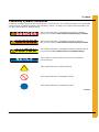
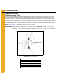
Cautionary Symbols Definitions
Cautionary symbols appear in this manual and on product decals. The symbols alert the user of potential
safety hazards, prohibited activities and mandatory actions. To help you recognize this information, we
use the symbols that are defined below.
NOTICE
DANGER
WARNING
CAUTION
This symbol indicates an imminently hazardous situation
which, if not avoided, will result in serious injury or death.
This symbol indicates a potentially hazardous situation
which, if not avoided, can result in serious injury or death.
This symbol indicates a potentially hazardous situation which,
if not avoided, can result in minor or moderate injury.
This symbol is used to address practices not related to
personal injury.
This symbol indicates a general hazard.
This symbol indicates a prohibited activity.
This symbol indicates a mandatory action.
ST-0005-2

2. Safety
8 PNEG-1461 12', 15', 18' and 21' Bulk Feed Tank Series and Grain Hopper Tank Series
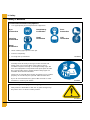
Safety Cautions
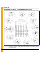
Use Personal Protective Equipment
Eye
Protection
Hearing
Protection
Hand
Protection
Head
Protection
Respiratory
Protection Foot
Protection
Fall
Protection
• Use appropriate personal protective equipment:
• Wear clothing appropriate to the job.
• Remove all jewelry.
• Tie long hair up and back.
ST-0004-1
Follow Safety Instructions
• Carefully read all safety messages in this manual and
safety signs on your machine. Keep signs in good
condition. Replace missing or damaged safety signs. Be
sure new equipment components and repair parts include
the current safety signs. Replacement safety signs are
available from the manufacturer.
• Learn how to operate the machine and how to use controls
properly. Do not let anyone operate without instruction.
• If you do not understand any part of this manual or need
assistance, contact your dealer.
ST-0002-1
Install and Operate Equipment Properly
• This product is intended for the use of grain storage only.
Any other use is a misuse of the product.
ST-0057-1

2. Safety
PNEG-1461 12', 15', 18' and 21' Bulk Feed Tank Series and Grain Hopper Tank Series 9
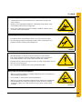
Maintain Equipment and Work Area
• Understand service procedures before doing work. Keep area
clean and dry.
• Never service equipment while it is operating. Keep hands, feet,
and clothing away from moving parts.
• Keep your equipment in proper working condition. Replace worn
or broken parts immediately.
ST-0003-1
Sharp Edge Hazard
• This product has sharp edges, which can cause serious injury.
• To avoid injury, handle sharp edges with caution and always use
proper protective clothing and equipment.
ST-0036-2
Store Bin Sheets Properly
• Sidewall bundles or sheets must be stored in a safe manner.
The safest method of storing sidewall bundles is by laying them
horizontally with the arch of the sheet upward, like a dome.
• Sidewall sheets stored on edge must be secured so that they cannot
fall over and cause injury.
• Use care when handling and moving sidewall bundles.
ST-0058-1
Stay Clear of Hoisted Equipment
• Always use proper lifting or hoisting equipment when assembling or
disassembling equipment.
• Do not walk or stand under hoisted equipment.
• Always use sturdy and stable supports when needed for installation.
Not following these safety precautions creates the risk of falling
equipment, which can crush personnel and cause serious injury
or death.
ST-0047-1

2. Safety
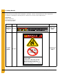
10 PNEG-1461 12', 15', 18' and 21' Bulk Feed Tank Series and Grain Hopper Tank Series
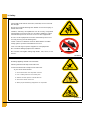
> 300 lbs
(1.34 kN)
Ladder Load Limit
• The ladder load limit is 300 LBS (1.34 kN). Do not exceed
this weight.
• Excessive load will damage the ladder and severe injury or
death will result.
• Ladders, stairways and platforms are for use by competent
and trained personnel only. Do not allow children or other
unauthorized persons to have access to the equipment.
• Access to the equipment must be restricted by the use of
security fencing and lockable gates.
• Lower sections of ladders must be fitted with a lockable
safety gate to prevent unauthorized access.
• Lock out and tag out power supplies to all equipment.
• Do not attach lifting equipment to ladders.
• Do not work at heights during high winds, rain, snow, or ice
storms.
ST-0059-2
Do Not Enter Bin
• Rotating flighting will kill or dismember.
• Flowing material will trap and suffocate.
• Crusted material will collapse and suffocate.
- If you must enter the bin:
1. Shut off and lock out all power sources.
2. Use a safety harness and safety line.
3. Station another person outside the bin.
4. Avoid the center of the bin.
5. Wear proper breathing equipment or respirator.
ST-0061-1

2. Safety
PNEG-1461 12', 15', 18' and 21' Bulk Feed Tank Series and Grain Hopper Tank Series 11
Safety Sign-Off Sheet
Below is a sign-off sheet that can be used to verify that all personnel have read and understood the safety
instructions. This sign-off sheet is provided for your convenience and personal record keeping.
Date Employee Name Supervisor Name
ST-0007

12 PNEG-1969 ETL Listed TopDry Series 2000 Autoflow
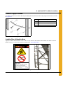
3. Safety Decals
The safety decals on your equipment are safety indicators which must be carefully read and understood
by all personnel involved in the installation, operation, service and maintenance of the equipment.
To replace a damaged or missing decal, contact us to receive a free replacement.
GSI Decals
1004 E. Illinois St.
Assumption, IL 62510
Tel: 1-217-226-4421
Location Decal No. Decals Description
Located on
inside of bin
collar. DC-2123 Danger, Keep
Clear of
Augers
Located
on bin
ladders. DC-2307 Danger, Do not
exceed load
limit.
DANGERDANGER
Rotating flighting will
kill or dismember.
Flowing material will
trap and suffocate.
Crusted material will
collapse and suffocate. DC-2123
GSI Group 217-226-4421
DC-2307GSI Group, 217-226-4421
DANGER
DO NOT EXCEED LADDER
LOAD LIMIT
Load limit = 300 LBS (136 kg)
Excessive load will damage
ladder resulting in injury or death.
> 300 lbs
(136 kg)

PNEG-1461 12', 15', 18' and 21' Bulk Feed Tank Series and Grain Hopper Tank Series 13
4. General Information
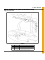
Bulk Feed Tank Assembly Manual General Instructions
This product is intended for the use of storing feed only. Any other use is a misuse of the product.
While every effort has been made to keep the edges from being sharp, please wear the proper protective
clothing while erecting the Bulk Feed Tank.
Our company recommends that you contact the local power company and have a representative review
the installation so the wiring will be compatible with their system and so that you will have adequate power
supplied to the unit.
A Bulk Feed Tank weighs a minimum of 444 lbs. (201 kg). All precautions should be taken when raising
the tank to its feet. Follow the instructions given later in this manual.
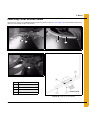
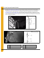
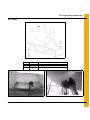
The safety pages show you where you can find the safety decals. The photographs show exactly
where the decals should be. If a decal has been damaged or is missing contact our company for a
free replacement.
First, read the assembly manual completely before starting to assemble the Bulk Feed Tank. Check the
shipment with the packing list to be sure there are no shortages.
1. Decal protective mask must be removed when assembling tank. Mask may become difficult to
remove if left exposed to sunlight.
2. Vertical seams must be staggered on all sidewall rings.
3. When legs extend up 2 rings, the leg holes must be in alignment in the bottom 2 rings.
4. All hopper seams and the hopper collar use truss head bolts. The heads of the bolts must be on the
inside of the tank.
5. Hex head bin bolts are used on all sidewall and roof seams with the bolt heads on the outside of
the bin.
6. Hex head bolts are to be used on all leg to sidewall connections with the bolt heads on the inside of
the tank.
7. All bolts are to be tightened from the nut side only. Do not allow bolt heads to spin.
8. Drift punches can be used to align holes.
9. All vertical sidewall sheet seams must be overlapped in the same direction.
10. A hole spacing of 3-1/8" is used at the top of all top sidewall sheets and at the bottom of all bottom
sidewall sheets.

4. General Information
14 PNEG-1461 12', 15', 18' and 21' Bulk Feed Tank Series and Grain Hopper Tank Series
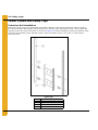
Selecting the Proper Site
The selected site should be level, firm and free from underlying debris. The tank can be installed
satisfactorily on slopes, but as the slope increases, additional labor and materials are required for the
foundation. The concrete foundation surfaces must be level. If some fill is required, it should be watered
and tamped thoroughly to prevent uneven settling from the weight of the tank. Good water drainage should
be provided to prevent water collecting under or around the tank. The site must allow convenient access
for loading and unloading and plus provide additional space for future units. Also, consider the positioning
of handling equipment, availability of electricity, etc.
Tools
Tools recommended for assembly of Bulk Feed Tanks.
1. Assorted sizes of combination wrenches
2. Hammer
3. 3-12" Long drift punches
4. 1 Large flathead screwdriver
5. 1 Pair of slip joint pliers
6. Two (2) adjustable wrenches
7. Ratchet and sockets
8. Impact wrenches and sockets (if available)

PNEG-1461 12', 15', 18' and 21' Bulk Feed Tank Series and Grain Hopper Tank Series 15
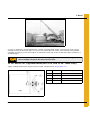
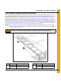
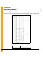
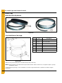
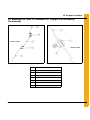
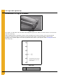
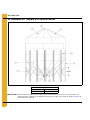
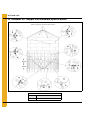
5. Foundation
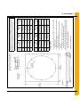
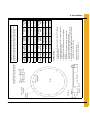
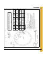
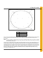
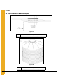
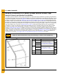
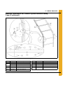
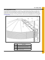
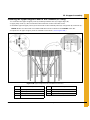
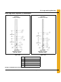
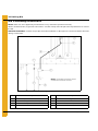
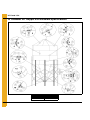
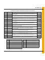
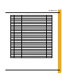
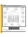
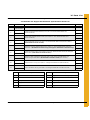
Figure 5A 12' 2-8 Rings BFT/GHT Square Pad
# of
Rings Slab
Thickness (D) Concrete
Volume Wire Mesh
Area # of Column
Legs
2-5 15" 9.1 Cu. Yards 196 Sq. Ft. 8
6 16" 9.7 Cu. Yards 196 Sq. Ft. 8
716" 9.7 Cu. Yards 196 Sq. Ft. 8
8 17" 10.3 Cu. Yards 196 Sq. Ft. 8
# of
Rings Slab
Thickness (D) Concrete
Volume Wire Mesh
Area # of Column
Legs
2-5 381 mm 6.93 Cu. Meters 18.21 Sq. Meters 8
6 406 mm 7.40 Cu. Meters 18.21 Sq. Meters 8
7406 mm 7.40 Cu. Meters 18.21 Sq. Meters 8
8 432 mm 7.86 Cu. Meters 18.21 Sq. Meters 8
GENERAL NOTES:
1. Foundation recommendations are based on 3500 lbs./ft.^2 allowable
soil bearing capacity.
2. Foundation recommendations are based on a minimum compressive
strength of 3000 PSI at 28 days.
3. The foundation site must be well drained and free of vegetation
and debris.
4. The foundation should be level within 1/4" overall and within
± 1/8" in any 10 ft. length along the anchor bolt circle.
5. Material estimates do not include allowance for shrinkage and waste.
6. These layouts are recommendations for GSI tanks only. Consult GSI
engineering for special tank foundations.
* Applies to 45° hopper tank only.
All instructions shall be construed as recommendations only. The actual
installation may vary according to local conditions. The GSI Group assumes
no liability for results arising from the use of such recommendations.
*
*
Anchor bolt 5/8" x 8" (203 mm) bolt with a
1/8" thick x 1-3/4" O.D. washer on head.
6" Maximum
Grade

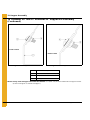
5. Foundation
16 PNEG-1461 12', 15', 18' and 21' Bulk Feed Tank Series and Grain Hopper Tank Series
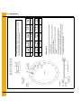
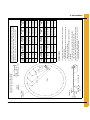
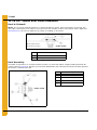
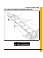
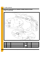
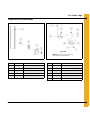
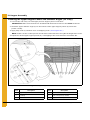
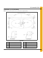
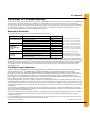
Figure 5B 12' 2-8 Rings BFT/GHT Round Pad
# of
Rings Slab
Thickness (D) Concrete
Volume Wire Mesh
Area # of Column
Legs
2-5 15" 7.1 Cu. Yards 155 Sq. Ft. 8
6 16" 7.6 Cu. Yards 155 Sq. Ft. 8
716" 7.6 Cu. Yards 155 Sq. Ft. 8
8 17" 8.1 Cu. Yards 155 Sq. Ft. 8
# of
Rings Slab
Thickness (D) Concrete
Volume Wire Mesh
Area # of Column
Legs
2-5 381 mm 5.45 Cu. Meters 14.40 Sq. Meters 8
6 406 mm 5.81 Cu. Meters 14.40 Sq. Meters 8
7406 mm 5.81 Cu. Meters 14.40 Sq. Meters 8
8 432 mm 6.18 Cu. Meters 14.40 Sq. Meters 8
GENERAL NOTES:
1. Foundation recommendations are based on 3500 lbs./ft.^2 allowable
soil bearing capacity.
2. Foundation recommendations are based on a minimum compressive
strength of 3000 PSI at 28 days.
3. The foundation site must be well drained and free of vegetation
and debris.
4. The foundation should be level within 1/4" overall and within
± 1/8" in any 10 ft. length along the anchor bolt circle.
5. Material estimates do not include allowance for shrinkage and waste.
6. These layouts are recommendations for GSI tanks only. Consult GSI
engineering for special tank foundations.
* Applies to 45° hopper tank only.
All instructions shall be construed as recommendations only. The actual
installation may vary according to local conditions. The GSI Group assumes
no liability for results arising from the use of such recommendations.
*
*
6" Maximum
Grade
Anchor bolt 5/8" x 8" (203 mm) bolt with a
1/8" thick x 1-3/4" O.D. washer on head.
8 Legs

5. Foundation
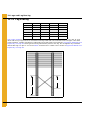
PNEG-1461 12', 15', 18' and 21' Bulk Feed Tank Series and Grain Hopper Tank Series 17
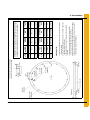
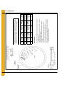
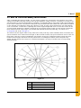
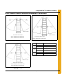
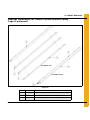
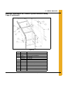
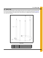
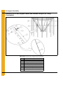
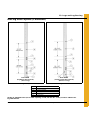
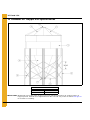
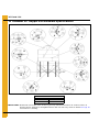
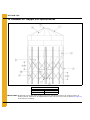
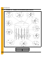
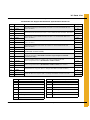
Figure 5C 12' 8-10 Rings BFT/GHT Round Pad
# of
Rings Footing
Depth (D) Slab
Thickness (T) Concrete
Volume Wire Mesh
Area # of Column
Legs
815" 4" 5.0 Cu. Yards 175 Sq. Ft. 12
9 18" 4" 5.8 Cu. Yards 175 Sq. Ft. 12
10 20" 4" 6.4 Cu. Yards 175 Sq. Ft. 12
# of
Rings Footing
Depth (D) Slab
Thickness (T) Concrete
Volume Wire Mesh
Area # of Column
Legs
8381 mm 102 mm 3.82 Cu. Meters 16.26 Sq. Meters 12
9 457 mm 102 mm 4.43 Cu. Meters 16.26 Sq. Meters 12
10 508 mm 102 mm 4.89 Cu. Meters 16.26 Sq. Meters 12
GENERAL NOTES:
1. Foundation recommendations are based on 3500 lbs./ft.^2 allowable
soil bearing capacity.
2. Foundation recommendations are based on a minimum compressive
strength of 3000 PSI at 28 days.
3. The foundation site must be well drained and free of vegetation
and debris.
4. The foundation should be level within 1/4" overall and within
± 1/8" in any 10 ft. length along the anchor bolt circle.
5. Material estimates do not include allowance for shrinkage and waste.
6. These layouts are recommendations for GSI tanks only. Consult GSI
engineering for special tank foundations.
* Applies to 60° hopper tank only.
** Applies to 45° and 60° hopper tanks.
All instructions shall be construed as recommendations only. The actual
installation may vary according to local conditions. The GSI Group assumes
no liability for results arising from the use of such recommendations.
*
**
*
**
Grade
6" Maximum
Anchor bolt 5/8" x 8" (203 mm) bolt with a
1/8" thick x 1-3/4" O.D. washer on head.
12 Legs

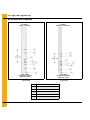
5. Foundation
18 PNEG-1461 12', 15', 18' and 21' Bulk Feed Tank Series and Grain Hopper Tank Series
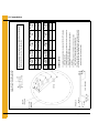
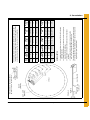
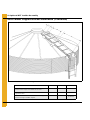
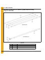
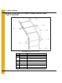
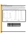
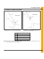
Figure 5D 12' 11 Rings BFT/GHT 16 Leg Round Pad
# of
Rings Footing
Depth (D) Slab
Thickness (T) Concrete
Volume Wire Mesh
Area # of Column
Legs
11 24" 4" 7.5 Cu. Yards 175 Sq. Ft. 16
# of
Rings Footing
Depth (D) Slab
Thickness (T) Concrete
Volume Wire Mesh
Area # of Column
Legs
11 610 mm 102 mm 5.73 Cu. Meters 16.26 Sq. Meters 16
GENERAL NOTES:
1. Foundation recommendations are based on 3500 lbs./ft.^2 allowable
soil bearing capacity.
2. Foundation recommendations are based on a minimum compressive
strength of 3000 PSI at 28 days.
3. The foundation site must be well drained and free of vegetation
and debris.
4. The foundation should be level within 1/4" overall and within
± 1/8" in any 10 ft. length along the anchor bolt circle.
5. Material estimates do not include allowance for shrinkage and waste.
6. These layouts are recommendations for GSI tanks only. Consult GSI
engineering for special tank foundations.
All instructions shall be construed as recommendations only. The actual installation
may vary according to local conditions. The GSI Group assumes no liability for
results arising from the use of such recommendations.
6" Maximum
Grade
Anchor bolt 5/8" x 8" (203 mm) bolt with a
1/8" thick x 1-3/4" O.D. washer on head.
16 Legs

5. Foundation
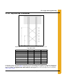
PNEG-1461 12', 15', 18' and 21' Bulk Feed Tank Series and Grain Hopper Tank Series 19
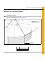
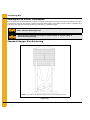
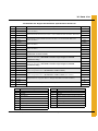
Figure 5E 15' 1-6 Rings BFT/GHT Round Pad
# of
Rings Slab
Thickness (D) Concrete
Volume Wire Mesh
Area # of Column
Legs
1-4 14" 11.0 Cu. Yards 255 Sq. Ft. 15
5 15" 11.8 Cu. Yards 255 Sq. Ft. 15
616" 12.6 Cu. Yards 255 Sq. Ft. 15
# of
Rings Slab
Thickness (D) Concrete
Volume Wire Mesh
Area # of Column
Legs
1-4 356 mm 8.41 Cu. Meters 23.69 Sq. Meters 15
5 381 mm 9.01 Cu. Meters 23.69 Sq. Meters 15
6406 mm 9.63 Cu. Meters 23.69 Sq. Meters 15
GENERAL NOTES:
1. Foundation recommendations are based on 3500 lbs./ft.^2 allowable
soil bearing capacity.
2. Foundation recommendations are based on a minimum compressive
strength of 3000 PSI at 28 days.
3. The foundation site must be well drained and free of vegetation
and debris.
4. The foundation should be level within 1/4" overall and within
± 1/8" in any 10 ft. length along the anchor bolt circle.
5. Material estimates do not include allowance for shrinkage and waste.
6. These layouts are recommendations for GSI tanks only. Consult GSI
engineering for special tank foundations.
All instructions shall be construed as recommendations only. The actual
installation may vary according to local conditions. The GSI Group assumes
no liability for results arising from the use of such recommendations.
Grade
6" Maximum
Anchor bolt 5/8" x 8" (203 mm) bolt with a
1/8" thick x 1-3/4" O.D. washer on head.
15 Legs

5. Foundation
20 PNEG-1461 12', 15', 18' and 21' Bulk Feed Tank Series and Grain Hopper Tank Series
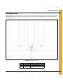
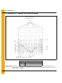
Figure 5F 15' 7-8 Rings BFT/GHT 60° Round Pad
# of
Rings Footing
Depth (D) Slab
Thickness (T) Concrete
Volume Wire Mesh
Area # of Column
Legs
714" 4" 6.3 Cu. Yards 225 Sq. Ft. 20
8 15" 4" 6.6 Cu. Yards 225 Sq. Ft. 20
# of
Rings Footing
Depth (D) Slab
Thickness (T) Concrete
Volume Wire Mesh
Area # of Column
Legs
7356 mm 102 mm 4.82 Cu. Meters 20.9 Sq. Meters 20
8 381 mm 102 mm 5.05 Cu. Meters 20.9 Sq. Meters 20
GENERAL NOTES:
1. Foundation recommendations are based on 3500 lbs./ft.^2 allowable
soil bearing capacity.
2. Foundation recommendations are based on a minimum compressive
strength of 3000 PSI at 28 days.
3. The foundation site must be well drained and free of vegetation
and debris.
4. The foundation should be level within 1/4" overall and within
± 1/8" in any 10 ft. length along the anchor bolt circle.
5. Material estimates do not include allowance for shrinkage and waste.
6. These layouts are recommendations for GSI tanks only. Consult GSI
engineering for special tank foundations.
All instructions shall be construed as recommendations only. The actual installation
may vary according to local conditions. The GSI Group assumes no liability for
results arising from the use of such recommendations.
6" Maximum
Grade
20 Legs
Anchor bolt 5/8" x 8" (203 mm) bolt with a
1/8" thick x 1-3/4" O.D. washer on head.
Page is loading ...
Page is loading ...
Page is loading ...
Page is loading ...
Page is loading ...
Page is loading ...
Page is loading ...
Page is loading ...
Page is loading ...
Page is loading ...
Page is loading ...
Page is loading ...
Page is loading ...
Page is loading ...
Page is loading ...
Page is loading ...
Page is loading ...
Page is loading ...
Page is loading ...
Page is loading ...
Page is loading ...
Page is loading ...
Page is loading ...
Page is loading ...
Page is loading ...
Page is loading ...
Page is loading ...
Page is loading ...
Page is loading ...
Page is loading ...
Page is loading ...
Page is loading ...
Page is loading ...
Page is loading ...
Page is loading ...
Page is loading ...
Page is loading ...
Page is loading ...
Page is loading ...
Page is loading ...
Page is loading ...
Page is loading ...
Page is loading ...
Page is loading ...
Page is loading ...
Page is loading ...
Page is loading ...
Page is loading ...
Page is loading ...
Page is loading ...
Page is loading ...
Page is loading ...
Page is loading ...
Page is loading ...
Page is loading ...
Page is loading ...
Page is loading ...
Page is loading ...
Page is loading ...
Page is loading ...
Page is loading ...
Page is loading ...
Page is loading ...
Page is loading ...
Page is loading ...
Page is loading ...
Page is loading ...
Page is loading ...
Page is loading ...
Page is loading ...
Page is loading ...
Page is loading ...
Page is loading ...
Page is loading ...
Page is loading ...
Page is loading ...
Page is loading ...
Page is loading ...
Page is loading ...
Page is loading ...
Page is loading ...
Page is loading ...
Page is loading ...
Page is loading ...
Page is loading ...
Page is loading ...
Page is loading ...
Page is loading ...
Page is loading ...
Page is loading ...
Page is loading ...
Page is loading ...
Page is loading ...
Page is loading ...
Page is loading ...
Page is loading ...
Page is loading ...
Page is loading ...
Page is loading ...
Page is loading ...
Page is loading ...
Page is loading ...
Page is loading ...
Page is loading ...
Page is loading ...
Page is loading ...
Page is loading ...
Page is loading ...
Page is loading ...
Page is loading ...
-
 1
1
-
 2
2
-
 3
3
-
 4
4
-
 5
5
-
 6
6
-
 7
7
-
 8
8
-
 9
9
-
 10
10
-
 11
11
-
 12
12
-
 13
13
-
 14
14
-
 15
15
-
 16
16
-
 17
17
-
 18
18
-
 19
19
-
 20
20
-
 21
21
-
 22
22
-
 23
23
-
 24
24
-
 25
25
-
 26
26
-
 27
27
-
 28
28
-
 29
29
-
 30
30
-
 31
31
-
 32
32
-
 33
33
-
 34
34
-
 35
35
-
 36
36
-
 37
37
-
 38
38
-
 39
39
-
 40
40
-
 41
41
-
 42
42
-
 43
43
-
 44
44
-
 45
45
-
 46
46
-
 47
47
-
 48
48
-
 49
49
-
 50
50
-
 51
51
-
 52
52
-
 53
53
-
 54
54
-
 55
55
-
 56
56
-
 57
57
-
 58
58
-
 59
59
-
 60
60
-
 61
61
-
 62
62
-
 63
63
-
 64
64
-
 65
65
-
 66
66
-
 67
67
-
 68
68
-
 69
69
-
 70
70
-
 71
71
-
 72
72
-
 73
73
-
 74
74
-
 75
75
-
 76
76
-
 77
77
-
 78
78
-
 79
79
-
 80
80
-
 81
81
-
 82
82
-
 83
83
-
 84
84
-
 85
85
-
 86
86
-
 87
87
-
 88
88
-
 89
89
-
 90
90
-
 91
91
-
 92
92
-
 93
93
-
 94
94
-
 95
95
-
 96
96
-
 97
97
-
 98
98
-
 99
99
-
 100
100
-
 101
101
-
 102
102
-
 103
103
-
 104
104
-
 105
105
-
 106
106
-
 107
107
-
 108
108
-
 109
109
-
 110
110
-
 111
111
-
 112
112
-
 113
113
-
 114
114
-
 115
115
-
 116
116
-
 117
117
-
 118
118
-
 119
119
-
 120
120
-
 121
121
-
 122
122
-
 123
123
-
 124
124
-
 125
125
-
 126
126
-
 127
127
-
 128
128
-
 129
129
-
 130
130


Cumberland 12', 15', 18' and 21' Bulk Feed Tank Series and Grain Hopper Tank Series Owner's manual
- Type
- Owner's manual
Ask a question and I''ll find the answer in the document
Finding information in a document is now easier with AI
Related papers
-
Cumberland 12', 15', 18' and 21' Bulk Feed Tank Series and Grain Hopper Tank Series Owner's manual
-
-
-
-
-
-
-
-
-
Other documents
-
 Riverside Furniture 75809 Assembly Instructions
-
 Riverside Furniture 75802 Assembly Instructions
-
Kmart 43271702 User manual
-
Shape Products SPE5536-72 Installation guide
-
 Polydome PD-1230 Assembly Instructions Manual
-
AGI Tower Ladder and Ladder Platforms Owner's manual
-
GSi PNEG-2132 Installation guide
-
Fisher & Paykel RS6121FRJK1 User guide
-
-
VEVOR H3602 User guide


