Page is loading ...

IMPORTANT: Before using this equipment, carefully read SAFETY PRECAUTIONS and all
instructions in this manual. Keep this Service Manual for future reference.
Model: A14145 and A14165
MicroPak 2e Custom
Integration Kit
LN-9627-00-R1 (08/2018) 1 / 45 www.carlisleft.com
EN
SERVICE MANUAL

NOTE: This manual has been changed from revision LN-9627-00 to revision
LN-9627-00-R1. Reasons for this change are noted under “Manual
Change Summary” inside the back cover of this manual.
LN-9627-00-R1 (08/2018) 2 / 45 www.carlisleft.com
MANUAL CHANGES
EN

CONTENTS
SAFETY: 4-8
Safety Precautions ..................................................................................................................................................... 4
Hazards / Safeguards ................................................................................................................................................. 5
INTEGRATOR KIT OPTIONS: 9-16
A14145-AABCD: Rotary Applicators ...........................................................................................................................9
Congurations ...........................................................................................................................................................10
Ethernet Connection .................................................................................................................................................. 12
Wiring for Pneumatic Parts ........................................................................................................................................ 13
Pneumatic Tubing ...................................................................................................................................................... 14
A14165-AAB: Automatic Applicators .........................................................................................................................15
Congurations ...........................................................................................................................................................16
PARTS LIST: 17-24
A14164: MicroPak 2e for Rotary Applicators ............................................................................................................. 17
A13987: Low Voltage Cable Assembly ...................................................................................................................... 17
A13746: Low Voltage Cable Assembly ...................................................................................................................... 18
A14080: 24V 300W Power Supply ............................................................................................................................18
A13245: Multifunction I/O Board ................................................................................................................................19
A14158: Multifunction I/O Board DIN Rail Mounting Kit ............................................................................................19
A14096: Solenoid Assembly ...................................................................................................................................... 20
A14095: E/P Transducer DIN Rail Assembly .............................................................................................................20
A14166: MicroPak 2e Mounting Kit ...........................................................................................................................21
A13596: Pressure Transducer ................................................................................................................................... 21
A12433-25: 25’ Low Voltage Cable Extension ..........................................................................................................22
A13393-00: Low Voltage Cable Mounting Brackets ..................................................................................................22
A14168-00: DIN Rail Mounting Kit for Pneumatics ....................................................................................................23
A14174-00: DIN Rail Mounting Kit for 300W Power Supply ...................................................................................... 23
80557-00: AC Plug with Line Filter ............................................................................................................................24
INTRODUCTION: 25
About this manual ...................................................................................................................................................... 25
INSTALLATION: 26-27
Location of Connections ........................................................................................................................................... 27
ELECTRICAL CONNECTIONS: 28-32
MicroPak 2e Input Power Connections .....................................................................................................................28
Grounding the Input Power Supply (and Protecting Against Electrical Noise) ..........................................................29
Low Voltage Cable Connections (Output to Cascade) ..............................................................................................29
Interlock Connections ................................................................................................................................................31
Ethernet Cable Connections ......................................................................................................................................31
DIP Switch and Jumper Settings ...............................................................................................................................31
Conguration Screens ................................................................................................................................................31
(Continued on next page)
LN-9627-00-R1 (08/2018) 3 / 45 www.carlisleft.com
CONTENTS
EN

MECHANICAL MOUNTING: 33-42
MicroPak 2e HV Controller Cut Out ...........................................................................................................................33
Low Voltage Cable .....................................................................................................................................................34
Low Voltage Cable Extension ..................................................................................................................................... 35
Power Supply DIN Rail Mounting Hardware...............................................................................................................36
Mount kits for MIO/DIO Boards ..................................................................................................................................39
DIN Rail Mount kits for Solenoid Assemblies and E-to-P Units ..................................................................................40
CONTENTS (Cont.)
MANUAL CHANGE SUMMARY: 44
Manual Changes .......................................................................................................................................................44
LN-9627-00-R1 (08/2018) 4 / 45 www.carlisleft.com
CONTENTS
EN

CAUTION
!
WARNING
!
NOTE
SAFETY PRECAUTIONS
Before operating, maintaining or servicing any
Ransburg
electrostatic coating system
, read and understand all of the
technical and safety literature for your Ransburg products.
This manual contains information that is important for you
to know and understand. This information relates to USER
SAFETY and PREVENTING EQUIPMENT PROBLEMS.
To help you recognize this information, we use the following
symbols. Please pay particular attention to these sections.
A WARNING! states information to alert you to
a situation that might cause serious injury if
instructions are not followed.
A CAUTION! states information that tells how to
prevent damage to equipment or how to avoid a
situation that might cause minor injury.
A NOTE is information relevant to the procedure
in progress.
While this manual lists standard specications and service
procedures, some minor deviations may be found between
this literature and your equipment. Differences in local codes
and plant requirements, material delivery requirements, etc.,
make such variations inevitable. Compare this manual with
your system installation drawings and appropriate Ransburg
equipment manuals to reconcile such differences.
Careful study and continued use of this manual will provide a
better understanding of the equipment and process, resulting
in more efcient operation, longer trouble-free service and
faster, easier troubleshooting. If you do not have the manuals
and safety literature for your Ransburg system, contact your
local Ransburg representative or Ransburg.
WARNING
!
WARNING
!
The user MUST read and be familiar with the
Safety Section in this manual and the Ransburg
safety literature therein identied.
This equipment is intended to be used by
trained personnel ONLY.
This manual MUST be read and thoroughly un-
derstood by ALL personnel who operate, clean or
maintain this equipment! Special care should be tak-
en to ensure that the WARNINGS and safety require-
ments for operating and servicing the equipment are
followed. The user should be aware of and adhere
to ALL local building and re codes and ordinances
as well as NFPA-33 AND EN 50176 SAFETY STAN-
DARDS, LATEST EDITION, or applicable country
safety standards, prior to installing, operating, and/or
servicing this equipment.
The hazards shown on the following pages may
occur during the normal use of this equipment.
SAFETY
LN-9627-00-R1 (08/2018) 5 / 45 www.carlisleft.com
SAFETY
EN

AREA
Tells where hazards
may occur.
HAZARD
Tells what the hazard is.
SAFEGUARDS
Tells how to avoid the hazard.
Spray Area Fire Hazard
Improper or inadequate
operation and maintenance
procedures will cause a re
hazard.
Protection against inadvertent
arcing that is capable of
causing re or explosion is lost
if any safety interlocks are
disabled during operation.
Frequent Power Supply or
Controller shutdown indicates
a problem in the system
requiring correction.
Fire extinguishing equipment must be present in the
spray area and tested periodically.
Spray areas must be kept clean to prevent the
accumulation of combustible residues.
Smoking must never be allowed in the spray area.
The high voltage supplied to the atomizer must be
turned off prior to cleaning, ushing or maintenance.
Spray booth ventilation must be kept at the rates
required by NFPA-33, OSHA, country, and local
codes. In addition, ventilation must be maintained
during cleaning operations using ammable or
combustible solvents.
Electrostatic arcing must be prevented. Safe
sparking distance must be maintained between the
parts being coated and the applicator. A distance of
1 inch for every 10KV of output voltage is required
at all times.
Test only in areas free of combustible material.
Testing may require high voltage to be on, but only
as instructed.
Non-factory replacement parts or unauthorized
equipment modications may cause re or injury.
If used, the key switch bypass is intended for use
only during setup operations. Production should
never be done with safety interlocks disabled.
The paint process and equipment should be set up
and operated in accordance with NFPA-33, NEC,
OSHA, local, country, and European Health and
Safety Norms.
LN-9627-00-R1 (08/2018) 6 / 45 www.carlisleft.com
SAFETY
EN

AREA
Tells where hazards
may occur.
HAZARD
Tells what the hazard is.
SAFEGUARDS
Tells how to avoid the hazard.
Improper or inadequate
operation and maintenance
procedures will cause a
re hazard.
Protection against inadvertent
arcing that is capable of
causing re or explosion is lost
if any safety interlocks are
disabled during operation.
Frequent Power Supply or
Controller shutdown indicates
a problem in the system
requiring correction.
Electrostatic arcing must be prevented. Safe sparking
distance must be maintained between the parts being
coated and the applicator. A distance of 1 inch for
every 10KV of output voltage is required at all times.
Unless specically approved for use in hazardous
locations, all electrical equipment must be located
outside Class I or II, Division 1 or 2 hazardous
areas, in accordance with NFPA-33.
Test only in areas free of ammable or combustible
materials.
The current overload sensitivity (if equipped)
MUST be set as described in the corresponding
section of the equipment manual. Protection against
inadvertent arcing that is capable of causing re
or explosion is lost if the current overload sensitivity
is not properly set. Frequent power supply
shutdown indicates a problem in the system which
requires correction.
Always turn the control panel power off prior to
ushing, cleaning, or working on spray system
equipment.
Before turning high voltage on, make sure no objects
are within the safe sparking distance.
Ensure that the control panel is interlocked with the
ventilation system and conveyor in accordance with
NFPA-33, EN 50176.
Have re extinguishing equipment readily available
and tested periodically.
Improper operation or
maintenance may create
a hazard.
Personnel must be properly
trained in the use of this
equipment.
Personnel must be given training in accordance
with the requirements of NFPA-33, EN 60079-0.
Instructions and safety precautions must be read
and understood prior to using this equipment.
Comply with appropriate local, state, and national
codes governing ventilation, re protection,
operation maintenance, and housekeeping.
Reference OSHA, NFPA-33, EN Norms and your
insurance company requirements.
General Use and
Maintenance
Spray Area Explosion Hazard
LN-9627-00-R1 (08/2018) 7 / 45 www.carlisleft.com
SAFETY
EN

AREA
Tells where hazards
may occur.
HAZARD
Tells what the hazard is.
SAFEGUARDS
Tells how to avoid the hazard.
Spray Area /
High Voltage
Equipment
There is a high voltage device
that can induce an electrical
charge on ungrounded objects
which is capable of igniting
coating materials.
Inadequate grounding will
cause a spark hazard. A
spark can ignite many coating
materials and cause a re
or explosion.
Parts being sprayed and operators in the spray
area must be properly grounded.
Parts being sprayed must be supported on
conveyors or hangers that are properly grounded.
The resistance between the part and earth ground
must not exceed 1 meg ohm. (Refer to NFPA-33.)
Operators must be grounded. Rubber soled
insulating shoes should not be worn. Grounding
straps on wrists or legs may be used to assure
adequate ground contact.
Operators must not be wearing or carrying any
ungrounded metal objects.
When using an electrostatic handgun, operators
must assure contact with the handle of the applicator
via conductive gloves or gloves with the palm section
cut out.
NOTE: REFER TO NFPA-33 OR SPECIFIC
COUNTRY SAFETY CODES REGARDING
PROPER OPERATOR GROUNDING.
All electrically conductive objects in the spray area,
with the exception of those objects required by the
process to be at high voltage, must be grounded.
Grounded conductive ooring must be provided in
the spray area.
Always turn off the power supply prior to ushing,
cleaning, or working on spray system equipment.
Unless specically approved for use in hazardous
locations, all electrical equipment must be located
outside Class I or II, Division 1 or 2 hazardous
areas, in accordance with NFPA-33.
Avoid installing an applicator into a uid system
where the solvent supply is ungrounded.
Do not touch the applicator electrode while it is
energized.
Electrical Discharge
LN-9627-00-R1 (08/2018) 8 / 45 www.carlisleft.com
SAFETY
EN

AREA
Tells where hazards
may occur.
HAZARD
Tells what the hazard is.
SAFEGUARDS
Tells how to avoid the hazard.
High voltage equipment is
utilized in the process. Arcing
in the vicinity of ammable or
combustible materials may
occur. Personnel are exposed
to high voltage during operation
and maintenance.
Protection against inadvertent
arcing that may cause a re or
explosion is lost if safety circuits
are disabled during operation.
Frequent power supply shut-
down indicates a problem in
the system which requires
correction.
An electrical arc can ignite
coating materials and cause a
re or explosion.
Unless specically approved for use in hazardous
locations, the power supply, control cabinet, and all
other electrical equipment must be located outside
Class I or II, Division 1 and 2 hazardous areas in
accordance with NFPA-33 and EN 50176.
Turn the power supply OFF before working on the
equipment.
Test only in areas free of ammable or combustible
material.
Testing may require high voltage to be on, but only
as instructed.
Production should never be done with the safety
circuits disabled.
Before turning the high voltage on, make sure no
objects are within the sparking distance.
Electrical Discharge
Electrical
Equipment
Certain materials may be
harmful if inhaled, or if there is
contact with the skin.
Follow the requirements of the Safety Data Sheet
supplied by coating material manufacturer.
Adequate exhaust must be provided to keep the air
free of accumulations of toxic materials.
Use a mask or respirator whenever there is a chance
of inhaling sprayed materials. The mask must be
compatible with the material being sprayed and its
concentration. Equipment must be as prescribed
by an industrial hygienist or safety expert, and be
NIOSH approved.
Chemical HazardToxic Substances
Spray applicators require that aluminum inlet ttings
be replaced with stainless steel.
Aluminum is widely used in other spray application
equipment - such as material pumps, regulators,
triggering valves, etc. Halogenated hydrocarbon
solvents must never be used with aluminum
equipment during spraying, ushing, or cleaning.
Read the label or data sheet for the material you
intend to spray. If in doubt as to whether or not a
coating or cleaning material is compatible, contact
your coating supplier. Any other type of solvent may
be used with aluminum equipment.
Halogenated hydrocarbon
solvents for example:
methylene chloride and
1,1,1,-Trichloroethane are not
chemically compatible with the
aluminum that might be used
in many system components.
The chemical reaction
caused by these solvents
reacting with aluminum can
become violent and lead to an
equipment explosion.
Explosion Hazard —
Incompatible Materials
Spray Area
LN-9627-00-R1 (08/2018) 9 / 45 www.carlisleft.com
SAFETY
EN

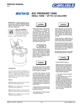
DescriptionItem #
A14145 - AABCD: ROTARY APPLICATORS
1 A14164-AABC MicroPak 2e Ethernet IP High Voltage Controller
2 A13245-01 Multifunction IO (MIO) Processor Board
3 A13987-10 or A13746-10 Internal Low Voltage Cable Assembly MicroPak 2e
4 A14096-01 Solenoid Assembly, Mechanical and Electrical
5 A14095-00 E-to-P Transducer Assembly
6 A13596-00 Pressure Transducer
7 A13591-00 Female Connector
Included in many congurations, but not shown above, is the 24V 300W Power Supply (A14080-00).
Not all components will be used in all congurations of A14145.
INTEGRATOR KIT OPTIONS
Figure 1: Major Components
MAJOR COMPONENTS - PARTS LIST (Figure 1)
Part #
2
6
7
4
5
1
3
LN-9627-00-R1 (08/2018) 10 / 45 www.carlisleft.com
INTEGRATOR KIT OPTIONS
EN

-01 (RMA-560, RMA-580, RWA-303 Direct X X
DIRECT CHARGE)
A11303,A12300, A12303, A12867,
A12868, A13364, A13367, A13100
-02 (RMA-202, RWA-101, Direct X X
DIRECT CHARGE) 79014, 78862
-03 RMA-303 - SPECIAL BEARING AIR Direct X X X
(70K @ 70 PSI BEARING LOW LIMIT)
-04 (MMA-570 DIRECT CHARGE) Direct X X
A11400,A12400, A12870, A13366
-05 (AEROBELL, AEROBELL II, Direct X X
AEROBELL 2.5, AEROBELL 168
DIRECT CHARGE)
RPM-5XXX-XXX, A12381, A12787,
77603, A10924
-09 (MMA-570 DIRECT CHARGE) Direct X X
A11400,A12400, A12870, A13366
-10 (MMA-303, MMA-570 INDIRECT Indirect X X
CHARGE)
A11400, A12400, A12870, A13366
-11 (AEROBELL, AEROBELL II, Direct X X
AEROBELL 2.5, AEROBELL 168
DIRECT CHARGE)
RPM-5XXX-XXX, A12381, A12787,
77603, A10924
-12 (AEROBELL II & 2.5 INDIRECT Indirect X X
CHARGE) 77603, A10924
-13 (AEROBELL 33 DIRECT CHARGE- Direct X X
30MM AND 57MM BELL CUP)
AER5000/AER5001
-14 (TURBODISK & TURBODISK 2) Direct X X
A11376, 78715
Description“AA” NO CASCADECharge HP-404 RP-404 RP-1000 LEPS-5002
TABLE AA - REFERENCE CONFIGURATIONS
REFERENCE CONFIGURATION TABLES
A14145 - AA - B - C - D
TABLE D - BELL SPEED / CASCADE CONTROL
TABLE C - UNILINK CONFIGURATION
TABLE B - MULTIFUNCTION I-O BOARD CONFIGURATION
TABLE AA - APPLICATOR TYPE AND CASCADE
BASIC PART NUMBER
LN-9627-00-R1 (08/2018) 11 / 45 www.carlisleft.com
INTEGRATOR KIT OPTIONS
EN

Description“AA” NO CASCADECharge HP-404 RP-404 RP-1000 LEPS-5002
-15 (RMA-303, RMA-570, RMA-590 Indirect X X
INDIRECT CHARGE)
A11300, A11600, A12869,
A13365, A13368
-16 MMA-303 - SPECIAL BEARING AIR Direct X X
(70K @ 70 PSI BEARING LOW LIMIT)
-17 (MMA-570 DIRECT CHARGE) Direct X
A11400,A12400, A12870, A13366
-18 (MMA-303, MMA-570 INDIRECT Indirect X
CHARGE) A11400, A12400,
A12870, A13366
-19 (AEROBELL, AEROBELL II, Direct X
AEROBELL 2.5, AEROBELL 168
DIRECT CHARGE)
RPM-5XXX-XXX, A12381, A12787,
77603, A10924
-20 (AEROBELL II & 2.5 INDIRECT Indirect X
CHARGE) 77603, A10924
-21 (AEROBELL 33 DIRECT CHARGE- Direct X
30MM AND 57MM BELL CUP)
AER5000/AER5001
-22 (TURBODISK & TURBODISK 2) Direct X
A11376, 78715
-23 (RMA-303, RMA-570, RMA-590 Indirect X
INDIRECT CHARGE) A11300, A11600,
A12869, A13365, A13368
-24 MMA-303 - SPECIAL BEARING AIR Direct X
(70K @ 70 PSI BEARING LOW LIMIT)
TABLE AA - REFERENCE CONFIGURATIONS (Cont.)
Description“B” Qty of Boards
UNILINK Mode“C”
Description“D”
TABLE B
TABLE C
TABLE D
1 Ethernet Control 1
2 Discrete Control 2
1 Disabled
2 Enabled
0 Cascade Control with Bell Speed
1 Bell Speed Only
LN-9627-00-R1 (08/2018) 12 / 45 www.carlisleft.com
INTEGRATOR KIT OPTIONS
EN

If the user plans to utilize the MicroPak 2e Ethernet/IP
interface for remote control, they must provide a network
connection for the Controller.
ETHERNET CONNECTION
(CAT 5 CABLE WITH RJ45 CONNECTOR):
Figure 2: External PLC Ethernet connection
Figure 3: Ethernet Connection for MIO/DIO Boards
Ethernet to external
network/PLC
ETHERNET CABLES
LN-9627-00-R1 (08/2018) 13 / 45 www.carlisleft.com
INTEGRATOR KIT OPTIONS
EN

Figure 4: Electrical Connections for E/P Transducer to Solenoids
SOLENOID 1 SOLENOID 2
V- V-V+ V+
LN-9627-00-R1 (08/2018) 14 / 45 www.carlisleft.com
INTEGRATOR KIT OPTIONS
EN

Figure 5: Pneumatic Connections for E/P Transducer to Solenoid
Tubing Part Number From Length (inches) To
A10893-07 T1 5 S4
A10893-07 T2 2 AIR IN
77536-08 T3 2.7 TURBINE PILOT
77536-08 T4 5.8 S6
77536-08 T5 6.7 EXHAUST OUT
77536-08 T6 5.2 S1
77536-08 S2 4 S5
77536-08 S3 9 BRAKE PILOT
PNEUMATIC POINT TO POINT CONNECTIONS
LN-9627-00-R1 (08/2018) 15 / 45 www.carlisleft.com
INTEGRATOR KIT OPTIONS
EN

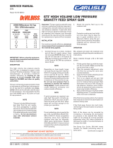
DescriptionItem # Part #
A14165 – AAB: AUTOMATIC APPLICATORS
Figure 6: Major Components
MAJOR COMPONENTS (Figure 6)
1 A14164 MicroPak 2e Ethernet IP High Voltage Controller
2 A13987-10 or A13746-10 Internal Low Voltage Cable Assembly MicroPak 2e
3 A13245-01 Multifunction IO (MIO) Processor Board
Included in many congurations, but not shown above, is the 24V 300W Power Supply (A14080-00).
Not all components will be used in all congurations of A14165.
2
1
3
LN-9627-00-R1 (08/2018) 16 / 45 www.carlisleft.com
INTEGRATOR KIT OPTIONS
EN

DescriptionDash # “A”
Description“B” Qty of Boards
-25 (RPA-1, RPA-2, MPA POWDER) DIRECT X
A11200, A12950, A11673
-26 (EVOLVER 202, EVOLVER 303, DIRECT X
EVOLVER 500 )
A11918, A11976, A12374
-27 NO ATOMIZER N/A X X
-28 NO ATOMIZER N/A X
-29 NO ATOMIZER N/A X
REFERENCE CONFIGURATION TABLES
A14165 - AA - B
TABLE B - MULTI I-O BOARD CONFIGURATION
TABLE AA - APPLICATOR TYPE AND CASCADE
BASIC PART NUMBER
0 Ethernet Control 0
2 Discrete Control 2
Charge HP-404 RP-404 RP-1000 LEPS5002 HP-505
TABLE AA
TABLE B
LN-9627-00-R1 (08/2018) 17 / 45 www.carlisleft.com
INTEGRATOR KIT OPTIONS
EN

A14164: MicroPak 2e Controller
PARTS LIST
The following are component parts that may be used
in the A14145 and A14165 Integrator Kits listed in this
manual. Congurations may vary depending on each
individual application.
Figure 7: MicroPak 2e Controller
Figure 8: Low Voltage Cable Assembly
A13987: Low Voltage Cable Assembly
LN-9627-00-R1 (08/2018) 18 / 45 www.carlisleft.com
PARTS LIST
EN

A13746: Low Voltage Cable Assembly
Figure 9: Low Voltage Cable Assembly
A14080: 24V 300W Power Supply
Figure 10: 24V 300W Power Supply
LN-9627-00-R1 (08/2018) 19 / 45 www.carlisleft.com
PARTS LIST
EN

A13245: Multifunction I/O Board
Figure 11: Multifunction I/O Board
A14158: Multifunction I/O Board DIN Rail Mounting Kit
Figure 12 – Multifunction I/O Board DIN Rail Mounting Kit
LN-9627-00-R1 (08/2018) 20 / 45 www.carlisleft.com
PARTS LIST
EN
/