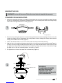
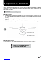
MyFan F36 Harlequin is a ceiling fan designed for indoor use. It can provide air circulation and cooling effect in rooms with a minimum height of 2.1 meters from the floor to the blades. The fan has a motor with adjustable speed settings, allowing you to customize the airflow intensity. It comes with five or six blades, depending on the model, and a frosted glass shade for the light fixture. The fan is equipped with a rotary switch for easy control of speed and light settings.
MyFan F36 Harlequin is a ceiling fan designed for indoor use. It can provide air circulation and cooling effect in rooms with a minimum height of 2.1 meters from the floor to the blades. The fan has a motor with adjustable speed settings, allowing you to customize the airflow intensity. It comes with five or six blades, depending on the model, and a frosted glass shade for the light fixture. The fan is equipped with a rotary switch for easy control of speed and light settings.


-
 1
1
-
 2
2
-
 3
3
-
 4
4
-
 5
5
-
 6
6
-
 7
7
-
 8
8
-
 9
9
-
 10
10
-
 11
11
-
 12
12


MyFan F36 Harlequin is a ceiling fan designed for indoor use. It can provide air circulation and cooling effect in rooms with a minimum height of 2.1 meters from the floor to the blades. The fan has a motor with adjustable speed settings, allowing you to customize the airflow intensity. It comes with five or six blades, depending on the model, and a frosted glass shade for the light fixture. The fan is equipped with a rotary switch for easy control of speed and light settings.
Ask a question and I''ll find the answer in the document
Finding information in a document is now easier with AI
Other documents
-
 Hunter Pacific X-Over DC Ceiling Fan User manual
-
 HPM CF13AC4BLEDWE User manual
-
Eglo STRADBROKE Ceiling Fan User manual
-
Fanimation Aire Decor BP200-BP230 220V Owner's manual
-
-
-
-
-
-
 Cool Attic CX1801HUB Operating instructions


