Page is loading ...

SERENE AC CEILING FANS WITH TRI-COLOUR LIGHT
Instruction Manual

Serene AC Ceiling Fans with Tri-colour Light
Cat. No: CF12AC4BLEDWE, CF13AC4BLEDWE
Instruction Manual
1 QUICK-FIT BLADES INSTALLATION
1. The hangsure style is suitable for both flat and inclined ceilings (up to maximum angle of 18°).
2. This fan has been supplied with a 3 speed fan control. It is designed to operate a single fan only.
3. The fan is to be installed so that the fan blades are more than 2.1m above floor level. Fan blades should have clearances >300mm
from any obstacles.
4. During installation a switch disconnection should be incorporated in the supply circuit (switch included).
5. The lamp in the fan is built-in and is non-replaceable.
6. If using remote control kit refer to instruction manual for detailed instructions.
7. Blades provided are paired for individual fan and must not be mixed with blades from other fans. This may affect performance
and cause vibration/wobble. If unusual oscillating movement is observed, stop using the ceiling fan immediately and contact
Legrand Australia, its service agent or a suitably qualified person.
8. Fan has “Light Colour Switch” which is marked WW - Warm White, CW - Cool White (Factory set), NW - Natural White. This colour
selection is done once the fan is installed by the electrician.
IMPORTANT CONSIDERATIONS
• Motor assembly (x1)
• ABS plastic blades (x4)
• Blade screws (x9)
• Mounting bracket (x1)
• Mounting bracket screw (x2)
(Timber use only)
• Plastic anchors (x2)
• Fan wall control and light
switch (x1)
PLEASE READ ALL INSTRUCTIONS CAREFULLY. RETAIN FOR FUTURE REFERENCE.
Box contents
CF12AC4BLEDWE
CF13AC4BLEDWE
2
INDOOR
OUTDOOR
Product Specifications
CF12AC4BLEDWE CF13AC4BLEDWE
Supply Voltage 230-240 V ~ 50 Hz
Power (Motor) 70 W 75 W
Maximum Airflow 9,480 m3/h 10,500 m3/h
Fan Size 1220 mm, 48” 1320 mm, 52”
Product Weight 5.6 Kgs 6.5 Kgs
Power Factor 0.95 @ 240 V a.c. 50 Hz
LAMP
Type LED light
Lamp 16 W
Lumen
Warm White (3000K):1250 lm
Cool White (4000K):1400 lm
Natural White (5700K):1290 lm
Dimming Yes - with compatible wall dimmmer
(NOT BY REMOTE CONTROL)
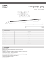
A. Turn the top motor housing
anticlockwise and lift upward.
B. Insert the blade into the rectangular
slot on the side of the motor body.
C. Tighten screws provided in kit. Refit the top
motor housing to the fan body by reversing step1.
Insert blades (x4)
Screws per blade (x2)
Max. Torque:0.5 Nm
Note: Make sure that the blades are oriented as shown above and ensure the top motor housing has locked back into place.
REVERSIBLE
MODE
SUMMER/WINTER

2 FIXING THE MOUNTING BRACKET TO CEILING
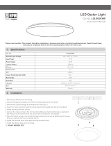
3 WIRING
For installations using wall control only.
3
Fix mounting bracket (supplied) firmly to timber or concrete.
This fan hanging system supports a maximum
18° angled ceiling installation.
Angled Ceiling Installation
Select a suitable location for the fan. Use the 2 coach screws provided (or similar) to make an attachment to a solid structural member.
Ensure the mounting method is capable of supporting a hanging weight of 30kg.
Warning: Ceiling fan must be mounted so that
blades are 2.1m from the floor and
300mm fromthe wall and other
obstructions to the blade tip.
Floor
More than 2.1m
More than 300 mm
ON
OFF
Brown/Red
FAN
DURING
WIRING
WALL CONTROLLER
ROTARY SWITCH
Speed 2
Grey
AN
To Terminal block
To Fan
Fan Active
Fan & light Neutral
Light Active
Earth
Blue/Black
Various
Yellow/ Green
Orange
Blue
Capacitor
(2.5µf)
(1.5µf)
LIGHT SWITCH ( Optional)
Main Supply
230-240 V a.c.
Speed 3
Speed 1

A. Connect supply wiring to the terminal block provided in hangsure bracket.
4 POWER SUPPLY CONNECTION TO TERMINAL BLOCK
ON
OFF
5 HANGING THE FAN ON THE BRACKET
4
• Place the fan assembly onto the mounting bracket.
• Ensure slot (B) of the hanging ball joint is positioned on notch (A) of the
mounting bracket (C) to prevent the fan from rotating when in operation
(See Fig.2).
• Cover the mounting bracket with the canopy. Ensure all electrical
wiring is tucked inside the canopy and that the wires are not
damaged during this step.
• Secure the canopy to the mounting bracket using the screws provided
(See Fig.3).
• After completing the electrical connection at the mounting bracket
terminal block, connect the ceiling fan by joining the male and female
connector plugs (See Fig.1).
• Make sure the terminal colour matches the corresponding terminal.
Fig.1
Fig.3
Fig.2
A
B
C
SUPPLY WIRING
BRACKET
L
230-240V ~
Max. Torque:0.5 Nm
LA

The ceiling fan comes with a Legrand Excel life rotary 3-speed control.
6
7
WALL SPEED CONTROLLER
ACCESSORIES (SOLD SEPARATELY)
Fan wall control with light switch (supplied)
Serene Ceiling AC Fan Remote Control Kit - White
(CFSERACREMOTE)
Serene Ceiling Fan Extension Downrod
750 mm x 21.5 mm-White
(CFSERDR750WE)
Serene Ceiling Fan Extension Downrod
1500 mm x 21.5 mm-White
(CFSERDR1500WE)
Downrods
Remote control
Note: Legrand Excel Life rotary 3 speed fan control with light switch (Cat. No:ED3FCSERLWE) is available as spare part.
5

8 SUMMER AND WINTER SWITCH
Summer and Winter switch
9 CHANGING THE COLOUR OF THE LED LIGHT
1. Switch OFF the mains.
2. Loosen the screw (A) to lift the lower canopy (B).
3. Locate the switch (C) and select the colour.
4. After selection, place the switch back inside safely, reposition the lower canopy (B) and secure it on the downrod by screw (A).
5. Turn mains back ON.
6
Warm White
3000K (WW)
Cool White
4000K (CW)
(Factory set)
Natural White
5700K (WW)
Summer Mode
Fan operates by rotating anti-clockwise to push cool air down
and pull warm air up, creating a wind chill effect of the air
moving around you.
Winter Mode
Fan operates in reverse by rotating clockwise to pull cool
air up and push warm air down, allowing for warm air to
be redistributed in the room saving heating running costs.
C
Lower canopy
SUMMER WINT ER
A
B

7
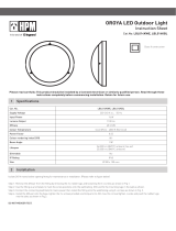
10 DOWNROD INSTALLATION
REMOVING THE ROD
Warning: Ceiling fan must be mounted so that blades are 2.1m from the floor and 300mm from the wall and other obstructions to
the blade tip (Refer to Section 2. Fixing the mounting bracket to ceiling on page 2).
Note: Max. Torque: 0.4 Nm for all screws.
REPLACING WITH DOWNROD
Note: Max. Torque: 0.4 Nm for all screws.
6
8
6
6
5
7
4
2
3
1
6
7
8
9
6
6
10
1
2
34
a. Lower the upper canopy.
b. Unscrew the screw (1) and lower the hanging ball (2).
c. Take out the clevis pin (3).
d. Unscrew the screw (4) and lift the lower canopy up (5).
e. Unscrew the screws (6) on the lower joint of downrod
and take the r-clip (7) out.
f. Remove the clevis pin (8).
g. Detach the downrod and take the connector wire out.
a. Assemble the upper and lower canopy onto the new downrod.
b. Connect the male (10) to the female (9) connector at the bottom of the
downrod and pull the wire from the top of downrod.
c. Assemble the downrod in place with all the screws (6), clevis pins (3,8)
and r-clip (7).
d. Ensure both clevis pins (3,8) are secure and all screws are tightened.
e. Place the hanging ball (2) into position and tighten the screw (1).
f. Set the lower and upper canopy onto downroad and tighten the screw (4).
Lower canopy
Upper canopy
ON
OFF DURING
WIRING
Make sure the power is switched OFF during installation.

12 / 2022 LE13927AA
PRODUCT NOTES
8
1. This product must be installed by a licensed electrician and used as per these instructions.
2. This product contains no serviceable parts and no attempt should be made to repair this product. If the product is faulty it should be
discarded.
3. This product must be cleaned periodically with a damp cloth. Cleaning agents and solvents should never be used.
4. This product has been designed to operate in ambient temperatures between 5°C to 40°C.
5. This product must be securely attached to a structural member for support. Fixing means (brackets) must be fixed to the
structural member with sufficient strength to withstand 4 times the weight of the ceiling fan.
6. During installation the mains supply wiring terminals should be tightened between 0.4Nm and 0.6Nm. Over-tightening may damage
the terminal.Under-tightening may result in hot joints.
7. This product is not intended to be exposed to direct weathering. It is not suitable for installation in hazardous and/or corrosive areas.
It is not suitable for marine environments such as areas subjected to salt spray and/or mist.
8. This product is not intended for use by young children or infirm persons without supervision. Young children should be supervised to
ensure that they do not play with the appliance.
9. Only those accessories as supplied by Legrand are designed for operation with the fan.
10. Extended exposure to UV rays (such as exposure to direct sunlight) may cause discolouration of this product.
11. The material in this product may vary in colour from batch to batch. Colour matching from one batch to another cannot be guaranteed.
12. This product has been designed to operate on a nominal supply voltage of 230-240 V a.c. 50 Hz.
13. After installation this product must be tested as required by the appropriate government and/or statutory regulations.
14. Legrand reserves the right to modify the specification of this product at any time.
■ Legrand (“we or us”) has given each purchaser who is a consumer (“you”) a warranty against defects in its products.
■ As a consumer, you are entitled to the benefit of the Warranty and should read and understand its terms. In addition,for the
purposes of the Australian and New Zealand Consumer Laws, we note the following:
■ Our contact details for the purpose of any claims made under the Warranty are below. Any claim under the Warranty must be
sent in writing to the following address:
NEW ZEALAND ONLY
Legrand New Zealand Ltd
106-124 Target Rd
GLENFIELD, AUCKLAND
0800 476 009
nz.sales@legrand.co.nz
AUSTRALIA ONLY
Legrand Australia Pty Ltd
Nexus Industry Park
Bldg 4, 43-47 Lyn Parade
PRESTONS, NSW 2170
1300 369 777
sales.orders@legrand.com.au
Warranty Statements
● If we accept your claim under the Warranty we will reimburse all your reasonable expenses in making and pursuing the claim,
including the cost of reimbursement of any defective products returned in the ordinary course to us at the address above by
post or other agreed means. Any such claim must be made within 14 days of your receiving notice of our acceptance of your
claim and include any necessary supporting documentation or invoices.
● As a consumer, you have rights under the Australian and New Zealand Consumer Laws and may have rights under other
applicable laws which cannot be excluded, restricted or modified. Those rights are in addition to any rights you have under
the Warranty.
■ Legrand offers this product with a 6 year (2 year + 4 year) express warranty. The first 2 years are in-home whereas the
following 4 years are parts only. To access this warranty please contact Legrand. The following conditions apply to this
express warranty:
● This warranty commences on the date of purchase.
● Under no circumstances Legrand will be responsible for rectification or costs under this express warranty without prior
written consent.
● The product must be installed by a licenced electrician and in accordance with these installation instructions.
● Minor vibration and variations between individual units is normal and not warrantable fault.
● Humming or vibration caused by ripple control signals is not warrantable fault.
These goods come with guarantees that cannot be excluded under the Australian and New Zealand Consumer Laws. You are
entitled to a replacement or a refund for a major failure and compensation for any other reasonably foreseeable loss or damage.
You are also entitled to have the goods repaired or replaced if the goods fail to be of acceptable quality and the failure does not
amount to a major failure.
6
Paper
/