Potter PAD100-LEDK User manual

Category
Fire protection
Type
User manual

This manual is also suitable for

Potter PAD100-LEDK is a versatile module that offers key-switch input and a mappable red LED for status indication. It's compatible with addressable fire systems using the PAD protocol. With easy address setting via dip switches, the module integrates seamlessly into your system. Ideal for key control of various system functions and status indication, the PAD100-LEDK enhances your fire alarm system's functionality.

Potter PAD100-LEDK is a versatile module that offers key-switch input and a mappable red LED for status indication. It's compatible with addressable fire systems using the PAD protocol. With easy address setting via dip switches, the module integrates seamlessly into your system. Ideal for key control of various system functions and status indication, the PAD100-LEDK enhances your fire alarm system's functionality.

Installation Manual: PAD100-LEDK LED with Key Switch Module
NOTICE TO THE INSTALLER
This manual provides an overview and the installation instructions for the PAD100-LEDK module. This module is only compatible
with addressable re systems that utilize the PAD Addressable Protocol.
All terminals are power limited and should be wired in accordance with the requirements of NFPA 70 (NEC) and NFPA 72 (National
Fire Alarm Code). Failure to follow the wiring diagrams in the following pages will cause the system to not operate as intended. For
further information, refer to the control panel installation instructions.
The module shall only be installed with listed control panels. Refer to the control panel installation manual for proper system
operation.
1. Description
The PAD100-LEDK module provides a mappable key-switch input making it ideal for key control of a variety of system functions.
The PAD100-LEDK provides a mappable red LED which can be used to indicate a variety of status conditions. The module mounts
on either a single gang box or Potter P32-BB/DBB box.
2. Setting the Address
All PAD protocol detectors and modules require an address prior to connection to the panel's SLC loop. Each PAD device's
address (i.e., detector and/or module) is set by changing the dip switches located on the device. PAD device addresses are
comprised of a seven (7) position dip switch used to program each device with an address ranging from 1–127.
Figure 1. PAD Device Dip Switch Addresses Table (Addresses 1127)
Note: Each "gray" box indicates that the dip switch is "On," and each "white" box indicates "Off."
The examples shown below illustrate a PAD device's dip switch settings: the 1st example shows a device not addressed where all
dip switch settings are in the default "Off" position, the 2nd illustrates an addressed PAD device via the dip switch settings.
Figure 2. Examples of PAD Device Showing Default Dip Switch Setting (Unaddressed) & Addressed PAD Device
Off
On
1 2 4 16
8 32 64 All dip switches are
shown in the "Off"
position. Off
On
1 2 4 16
832 64 Example shows this PAD device's
address = 42. Dip switches #2, 8 &
32 are in the "On" position.
Document 5406311-A 02/16
Potter Electric Signal Company, LLC St. Louis, MO Phone: (800) 325-3936 www.pottersignal.com
PAGE 1 OF 2
1 2 4 8 16 32 64 1 2 4 8 16 32 64 1 2 4 8 16 32 64 1 2 4 8 16 32 64 1 2 4 8 16 32 64
1 27 53 78 103
2 28 54 79 104
3 29 55 80 105
4 30 56 81 106
5 31 57 82 107
6 32 58 83 108
7 33 59 84 109
8 34 60 85 110
9 35 61 86 111
10 36 62 87 112
11 37 63 88 113
12 38 64 89 114
13 39 65 90 115
14 40 66 91 116
15 41 67 92 117
16 42 68 93 118
17 43 69 94 119
18 44 70 95 120
19 45 71 96 121
20 46 72 97 122
21 47 73 98 123
22 48 74 99 124
23 49 75 100 125
24 50 76 101 126
25 51 77 102 127
26 52 1 2 4 8 16 32 64 1 2 4 8 16 32 64 1 2 4 8 16 32 64
1 2 4 8 16 32 64 1 2 4 8 16 32 64
firealarmresources.com
INSTALLATION MANUAL: PAD100-LEDK LED WITH KEY SWITCH MODULE
Document 5406311-A 02/16
Potter Electric Signal Company, LLC St. Louis, MO Phone: (800) 325-3936 www.pottersignal.com
PAGE 2 OF 2
Before connecting a device to the SLC loop, take the following precautions to prevent potential damage to the SLC or device.
Power to the SLC is removed.
Field wiring on module is correctly installed.
Field wiring has no open or short circuits.
3. Technical Specications
Operating Voltage 24.0V
Max SLC Standby Current 200 μ A
Max SLC Alarm Current 200 μ A
Operating Temperature Range 32̊ to 120̊ F (0̊ to 49̊ C) Indoor Only
Operating Humidity Range 0 to 93% (non-condensing)
Max no. of Module Per Loop 127 units
Dimensions 4.75" L x 2.75" W x 1" D
Mounting Options Single gang box or Potter P32-BB/DBB
Shipping Weight 0.65 lbs
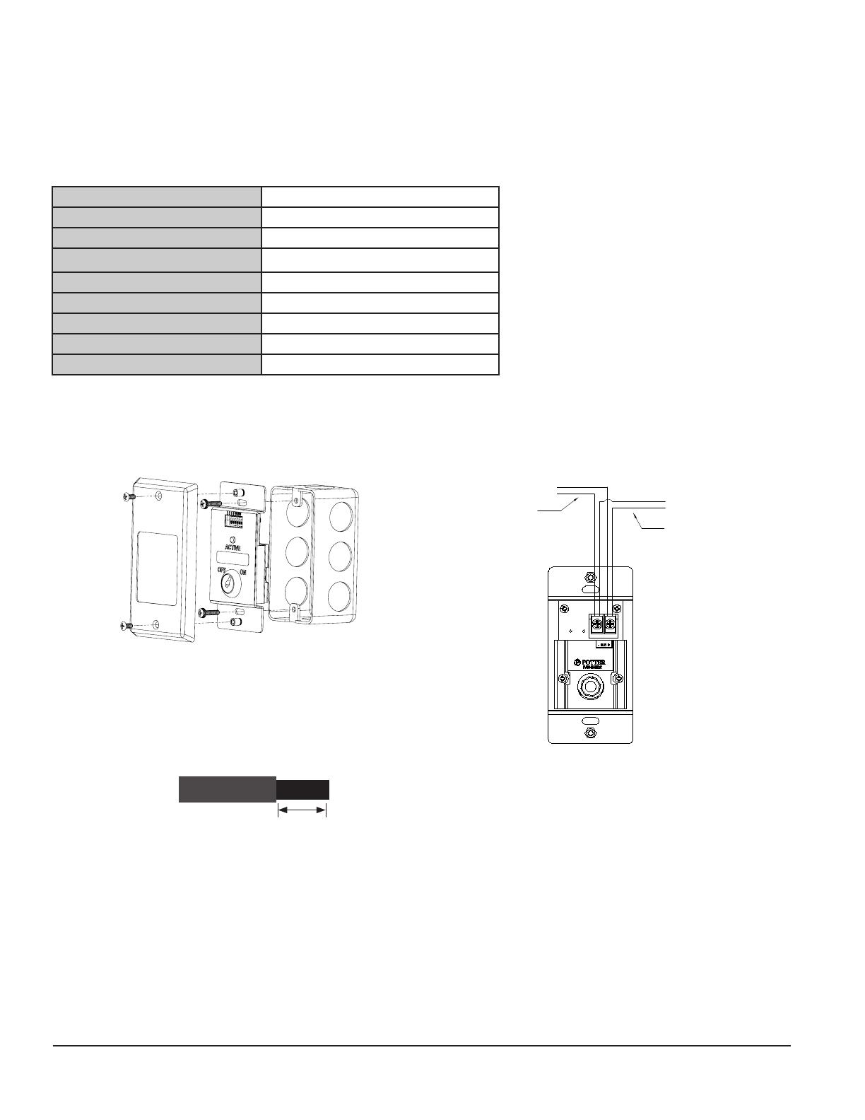
4. Wiring Diagrams
The wiring diagram shown below illustrates how to wire a PAD100-LEDK module. Additionally, an installation diagram shows how
to install the module using a compatible electrical box.
Figure 3. Examples of Installing a PAD100-LEDK Using a Compatible Electrical Box & Back View Wiring a PAD100-LEDK
Notes:
SLC wiring style supports the Class A, Class B and Class X.
SLC loop wiring (SLC+, SLC-) is power limited.
Wiring for terminals SLC+, SLC- are supervised.
All wiring is between #12 (max.) and #22 (min.).
Wire Preparation – Strip all wires 1/4 inch from their edges
as shown here:
– Stripping too much insulation may cause a ground fault.
– Stripping too little may cause a poor connection and subsequently an open circuit.
These instructions do not purport to cover all the details or variations in the equipment described, nor provide for
every possible contingency to be met in connection with installation, operation and maintenance.
Specications subject to change without prior notication.
For Technical Assistance contact Potter Electric Signal Company at 866-956-1211.
Actual performance is based on proper application of the product by a qualied professional.
Should further information be desired or should particular problems arise, which are not covered sufciently for
the purchaser's purpose, the matter should be referred to a distributor in your region.
TO NEXT MODULE
FROM FACP OR
PREVIOUS MODULE
1/4 inch
firealarmresources.com
  • Page 1 1
  • Page 2 2

Potter PAD100-LEDK User manual

Category
Fire protection
Type
User manual
This manual is also suitable for

Potter PAD100-LEDK is a versatile module that offers key-switch input and a mappable red LED for status indication. It's compatible with addressable fire systems using the PAD protocol. With easy address setting via dip switches, the module integrates seamlessly into your system. Ideal for key control of various system functions and status indication, the PAD100-LEDK enhances your fire alarm system's functionality.

Ask a question and I''ll find the answer in the document

Finding information in a document is now easier with AI