Page is loading ...

© 2001 dCS
Ltd
All rights reserved. Reproduction of this manual in any manner whatsoever,
without the written permission of dCS
1
is strictly forbidden. Additional copies of
this manual may be obtained from dCS.
Information contained in this manual is subject to change without notice, and
whilst it is checked for accuracy, no liabilities can be accepted for errors.
1
dCS
Ltd is Data Conversion Systems Ltd. Company registered in the England no. 2072115
dCS 974
Digital to Digital Converter
User Manual
Software version 1.0x
May 2001

dCS 974 User Manual Manual for Software Version 1.0x
dCS Ltd May 2001
Manual part no: DOC1241121A1
Page 2
Document No: OS-MA-A0124-112.1A1
Contact
dCS
on + 44 1799 531 999 email to: [email protected].uk
(inside the UK replace + 44 with 0) web site: www.dcsltd.co.uk

dCS 974 User Manual Manual for Software Version 1.0x
dCS Ltd May 2001
Manual part no: DOC1241121A1
Page 3
Document No: OS-MA-A0124-112.1A1
Contact
dCS
on + 44 1799 531 999 email to: [email protected].uk
(inside the UK replace + 44 with 0) web site: www.dcsltd.co.uk
P
RODUCT
O
VERVIEW
The dCS 974 DDC (Digital to Digital Converter) is a high performance real time
sample rate and format converter, developed from our highly successful
dCS 972. It is designed for studio applications where source material is available
in one format, but outputs are required in other digital formats in real time. For
example, archives might be made for storage in 24/192 or 24/176.4 formats,
and then used to produce output in SACD, DVD, CD and other multimedia
formats. AES3, SPDIF, SDIF-2 and DSD formats are all supported, and multiple
units may be synchronised for stable multi-channel operation.
The unit is mains powered and is housed in a 2U (3.5”) high 19” rack mounting
case. It may be controlled either from its front panel, or from a software based
remote control running on a PC. Frequently used Setups may be stored and re-
called later. The last setting is automatically stored on power down, so that fixed
installations may be set up at leisure, installed and then left alone. Unauthorised
alterations to settings may be prevented by a “panel lock out” feature.
Numerous monitoring functions are provided – both for the audio signal and for
messaging attached to it. The unit has bit activity and level meters, and
message manipulation. CRC, parity and invalid errors may be monitored and
reported, so that “right first time” transfer to disc plants may easily be achieved.
The unit is highly software based, and more functions and features are added
from time to time. Software updates from dCS are free!
2
Formats
• DSD at 2.822MS/s (see page 71)
• PCM from 192 kS/s down to 11.025 kS/s (see page 43)
• PCM data formats supported are: AES/EBU (XLR), Dual (2 wire) AES3
(XLR), Quad (4 wire) AES3 (XLR), SPDIF (Phono, Toslink and BNC) and
SDIF-2 (see page 70)
• DSD data formats supported are SDIF-2 (BNC), SDIF-3 (BNC) and DSD
Quad (4 wire - XLR)
Functions
• Sample Rate and Format Conversion (page 34)
• Multi-channel Sync capability (page 42)
• Bit for bit multiplex/de-multiplex mode (page 39)
• PCM to DSD, DSD to PCM
• DC Removal for DSD
• Multiple filters on many major sample rate conversions (page 45)
• Dither – 3 types (see page 47)
• Noise shaping – 10 different options on all major PCM sample rates (page
47).
• Output Level control with “Maximise” (page 48)
• Balance control (page 48).
• Digital Silence out with digital silence in (page 50)
Syncing
Comprehensive - can sync to Wordclock or AES reference, or signal, and sync
to video option available.
2
free if we email them, and you download from a PC COM port. Low cost if you ask us for EPROMs or other
media - we charge for media and handling.

dCS 974 User Manual Manual for Software Version 1.0x
dCS Ltd May 2001
Manual part no: DOC1241121A1
Page 4
Document No: OS-MA-A0124-112.1A1
Contact
dCS
on + 44 1799 531 999 email to: [email protected].uk
(inside the UK replace + 44 with 0) web site: www.dcsltd.co.uk
Monitoring
Bit Activity (page 56), Stereo Output Level (page 57), and CRC, Parity & Invalid
flag errors in the input data (page 52).
Test Generator
High quality (160 dB) signal generator with mHz resolution (page 53). Can be
dithered and/or noise shaped truncated.
Ease of Use
User programmable set-ups (page 61)
Pre-loaded setups
Remembers last settings
Lockouts (page 64)

dCS 974 User Manual Manual for Software Version 1.0x
dCS Ltd May 2001
Manual part no: DOC1241121A1
Page 5
Document No: OS-MA-A0124-112.1A1
Contact
dCS
on + 44 1799 531 999 email to: [email protected].uk
(inside the UK replace + 44 with 0) web site: www.dcsltd.co.uk
About this Manual
If you have not used a dCS 974 before, please read the section Using Your
dCS 974 For The First Time on page 110.
This manual has been arranged with the most commonly used sections placed
first:
• table of contents (page 6)
• step-by-step (page 10) and applications guides (page 22)
• detailed software and hardware information (page 34)
• technical information (page 70)
• information for first time users (page 110)
• options, maintenance and troubleshooting (page 114)
• index section (page 124)
References to other sections in the text have the Section Name, page … with
Section Name in bold. Sometimes, if you are reading a soft copy of the manual,
section names and page numbers are hyperlinks – click on them, and you will
go there.
IMPORTANT!
Important information is presented like this - ignoring this may cause you to
damage the unit, or invalidate the warranty.
The manual is designed to be helpful. If there are points you feel we could cover
better, or that we have missed out - please tell us.
About Sample Rates
All references to sample rates in this manual use the unit kS/s (kilo Samples per
second) rather than the technically incorrect kHz.

dCS 974 User Manual Manual for Software Version 1.0x
dCS Ltd May 2001
Manual part no: DOC1241121A1
Page 6
Document No: OS-MA-A0124-112.1A1
Contact
dCS
on + 44 1799 531 999 email to: [email protected].uk
(inside the UK replace + 44 with 0) web site: www.dcsltd.co.uk
C
ONTENTS
Product Overview ...............................................................................................3
About this Manual 5
About Sample Rates 5
Contents ..............................................................................................................6
Step-by-Step Guide ..........................................................................................10
Preliminaries 10
Step 1 – Selecting an Input 11
Connecting to a Single AES or SPDIF source 11
Connecting to a PCM SDIF-2 source 11
Connecting to a Dual AES Source 12
Connecting to a Quad AES source 12
Connecting to a DSD SDIF-2 source 12
Connecting to a DSD Quad source 12
Step 2 – Setting the Sync Source 13
Syncing to an External Wordclock 13
Syncing to an AES/EBU Reference 14
Step 3 - Setting a Conversion 15
Format Conversion 15
Sample Rate Conversion 16
Step 4 – Connecting the Outputs 18
Connecting a Single AES or SPDIF Output 18
Connecting the SDIF-2 Output 18
Connecting the Dual AES Outputs 18
Connecting the Quad AES or DSD Quad Outputs 18
Connecting the DSD SDIF-2 or DSD SDIF-3 Output 18
Step 5 – Reducing the Output Wordlength 19
Other Settings 21
Typical Applications.........................................................................................22
Converting a 24/96 recording to CD format 22
Demultiplexing a 24/96 Dual AES recording (Bit for Bit) 23
Upsampling a CD 24
General Sample Rate Conversion and Distribution 25
PCM to DSD 26
Using a Master Clock 27
Converting Quad AES to CD Format 28
Multi-channel Sample Rate Conversion – bit aligned sources 29
Multi-channel Sample Rate Conversion – Using a Master Clock 30
Multi-channel Sample Rate Conversion – with more alignment tolerance 31
Multi-channel Sample Rate Conversion – with multiple sample rates out 32
The Software – Menu and Setups ...................................................................34
Navigating through the Menu – what the On-Screen symbols mean 36
Top Menu 38
Sample Rate Conversion 38
Format Conversion 39
Error Monitoring 39
Test 39
Info 39
Bit Activity Monitors 40
Level Meters 40
Display 40
Sample Rate Conversion / Format Conversion Submenu 41
Audio Input Select 41
Sync Source 41
Multiple Channel Sync 42
Input Sample Rate 43
Output Sample Rate 43
Output Mode 45
Filter 45
Output Word Length 46

dCS 974 User Manual Manual for Software Version 1.0x
dCS Ltd May 2001
Manual part no: DOC1241121A1
Page 7
Document No: OS-MA-A0124-112.1A1
Contact
dCS
on + 44 1799 531 999 email to: [email protected].uk
(inside the UK replace + 44 with 0) web site: www.dcsltd.co.uk
Noise Shaping 47
Dither 47
AES Message Edit 48
SPDIF Message Edit 48
Gain/Balance and Maximise 48
Swap Channels 49
Phase 49
Detect Silence 50
De/Pre-Emphasis 50
Display Customise 50
Error Monitor Submenu 52
Error Hold and Reset 52
Test Submenu 53
Generator Overview 53
Controlling the Generator 53
Generator Amplitude Adjustment 54
Generator Frequency Adjustment 54
Self Test 55
Info Submenu 56
Bit Activity Monitor Submenu 56
Bit Activity Monitoring Overview 56
Setting the Monitor 56
Level Meters Submenu 57
Level Meter Overview 57
Turning the Level Meters On 57
Meter Type (Bar or Numerical) 58
Decay Time 58
Peak Hold 58
Using the dCS 974 to monitor a track 59
Watch Out for this One! 59
Display Submenu 60
Setups and Locking the Front Panel 61
Storing a Setup 61
Fixed Setups 63
Recalling a Setup 63
Locking Out Changes, and Unlocking Again 64
The Hardware – Controls and Connectors ....................................................66
Rear Panel 66
Signal Inputs 66
Signal Outputs 67
Control and Power 67
Additional Information 67
Front Panel 68
Power Indicator 68
OPERATION buttons 68
MEMORY buttons 68
LCD display 68
LED indicators 69
Rotary encoder 69
dCS 974 Technical Information.........................................................................70
Digital Data Formats Supported 70
DSD 71
PCM Input and/or Output Performance 73
Clocking 76
Sample Alignment 77
Multiple Channel Sync’ing 81
Multiple Channel Multiple Sample Rate Synchronising 83
Noise Shaping 84
Dither 85
Digital Interface Specifications 86
Message Handling 88
AES/EBU Message Handling 88
SPDIF Message Handling 89

dCS 974 User Manual Manual for Software Version 1.0x
dCS Ltd May 2001
Manual part no: DOC1241121A1
Page 8
Document No: OS-MA-A0124-112.1A1
Contact
dCS
on + 44 1799 531 999 email to: [email protected].uk
(inside the UK replace + 44 with 0) web site: www.dcsltd.co.uk
SDIF-2 Message Handling 90
SDIF-3 Message Handling 90
Power Consumption 91
Size, Weight and Operating Conditions 92
dCS 974 Performance Curves ...........................................................................94
General Technical Information......................................................................104
Word Length Reduction 104
Using Your dCS 974 For The First Time ........................................................110
What’s in the Box? 110
Supply Voltage Setting 110
Getting Started 110
Installing the Unit in a Rack 112
Options ............................................................................................................114
Locking to Video Sample Rates 114
Mains Supply Voltage 114
Ordering Options for a New Unit 114
Having Your Options Changed 114
Maintenance and Support..............................................................................116
Hardware 116
Service & Maintenance 116
User Changeable Parts 116
Software 117
Installing New Software 117
Warranty 118
Initial Warranty 118
Extended Warranty 118
Warranty Exclusions 118
Obtaining Service 118
Update or Calibration 119
Safety and Electrical Safety 119
Troubleshooting .............................................................................................120
FAQs 120
If You Need More Help 123
Other Information 123
Indexes and Software Version Numbers......................................................124
Definitions of Units 124
Tables 124
Figures 125
Keywords and Phrases 126
Owner Registration Transfer 131

dCS 974 User Manual Manual for Software Version 1.0x
dCS Ltd May 2001
Manual part no: DOC1241121A1
Page 9
Document No: OS-MA-A0124-112.1A1
Contact
dCS
on + 44 1799 531 999 email to: [email protected].uk
(inside the UK replace + 44 with 0) web site: www.dcsltd.co.uk

dCS 974 User Manual Manual for Software Version 1.0x
dCS Ltd May 2001
Manual part no: DOC1241121A1
Page 10
Document No: OS-MA-A0124-112.1A1
Contact
dCS
on + 44 1799 531 999 email to: [email protected].uk
(inside the UK replace + 44 with 0) web site: www.dcsltd.co.uk
S
TEP
-
BY
-S
TEP
G
UIDE
This section guides you through setting up the unit for basic operation. You may
find this useful if you have not used the dCS 974 for a while.
Preliminaries
The Quick Start Guide sheet details the menu structure and outlines the use of
the front panel controls. For more information, see Navigating through the
Menu – what the On-Screen symbols mean on page 36 and The Software –
Menu and Setups on page 34. We will be changing settings in either the
Sample Rate Conversion menu or the Format Conversion menu. Use the
rotary control to scroll up and down the screen and the Operation buttons to
change menu levels or select items.
Connect up with cables designed for digital audio:
• for AES/EBU interfaces use 110Ω screened, twisted pair cables fitted with
one male XLR connector and one female XLR connector.
• for DSD/SDIF or SPDIF BNC interfaces, use 75Ω coax cables fitted with
BNC plugs.
• for SPDIF RCA interfaces, use 75Ω coax cables fitted with RCA Phono
plugs.
• for SPDIF TOS interfaces, use Toslink fibre-optic cables.
Power up the unit and wait for about 20 seconds while it configures itself. The
screen will show:
Press the Recall button. When the screen displays the Recall Setup list, press
the Recall button again to change to the preset setup list, then press the Enter
button. Wait while the unit loads the default setup (Store A) then displays a
Status screen similar to this:
The Power and Unlocked indicators should be lit, the other indicators should
be off.

dCS 974 User Manual Manual for Software Version 1.0x
dCS Ltd May 2001
Manual part no: DOC1241121A1
Page 11
Document No: OS-MA-A0124-112.1A1
Contact
dCS
on + 44 1799 531 999 email to: [email protected].uk
(inside the UK replace + 44 with 0) web site: www.dcsltd.co.uk
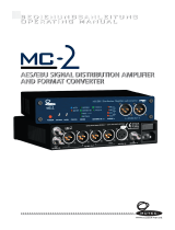
Step 1 – Selecting an Input
TOP LEVEL
Sample Rate Conversion
Audio Input Select AES 1 Default
Sync Source AES 2
Multi-Channel Sync AES 3
Input Sample Rate AES 4
Dual AES (1+2)
Quad AES
SPDIF1 (RCA)
SPDIF2 (BNC
SPDIF3 (TOS)
PCM SDIF-2
DSD SDIF-2
DSD Quad
Figure 1 – Audio Input Selection
Choose one of the following five sections:
Connecting to a Single AES or SPDIF source
do this: Connect your source equipment to the matching input on the dCS 974 rear panel
using suitable cables. An AES3 source (XLR connector) may be connected to
any of the four AES/EBU inputs.
do this: Press the →
→→
→ button twice to enter first the Sample Rate Conversion menu,
then the Audio Input Select menu. Use the rotary control to scroll down the list
until the cursor is beside your chosen input (either AES 1, AES 2, AES 3, AES 4,
SPDIF 1 (RCA), SPDIF2 (BNC) or SPDIF3 (Toslink)). Press the Set button.
The screen will change back to the Sample Rate Conversion menu. Proceed
to Step 2.
Connecting to a PCM SDIF-2 source
do this: Connect the SDIF-2 output on your source equipment to the upper block of
DSD/SDIF connectors on the dCS 974 rear panel using 3 coax cables. Connect
CH1 out to CH1 IN, CH2 out to CH2 IN, CLK out to WCLK IN. Fit a 75Ω
terminating plug to the nearby LOOP OUT connector.
do this: Press the →
→→
→ button twice to enter first the Sample Rate Conversion menu,
then the Audio Input Select menu. Use the rotary control to scroll down the list
until the cursor is beside PCM SDIF-2. Press the Set button to select it.
The screen will change back to the Sample Rate Conversion menu. Proceed
to Step 2.

dCS 974 User Manual Manual for Software Version 1.0x
dCS Ltd May 2001
Manual part no: DOC1241121A1
Page 12
Document No: OS-MA-A0124-112.1A1
Contact
dCS
on + 44 1799 531 999 email to: [email protected].uk
(inside the UK replace + 44 with 0) web site: www.dcsltd.co.uk
Connecting to a Dual AES Source
do this: Check that your source equipment is capable of Dual AES operation.
do this: Connect the AES 1 (or AES A) output on your source equipment to the AES 1
input on the dCS 974 rear panel and the AES 2 (or AES B) output to the AES 2
input, using two XLR cables. Ensure the cables are not swapped.
do this: Press the →
→→
→ button twice to enter first the Sample Rate Conversion menu,
then the Audio Input Select menu. Use the rotary control to scroll down the list
until the cursor is beside Dual AES. Press the Set button to select it.
The screen will change back to the Sample Rate Conversion menu. Proceed
to Step 2.
Connecting to a Quad AES source
do this: Check that your source equipment is capable of Quad AES operation.
do this: Connect the AES 1 output on your source equipment to the AES 1 input on the
dCS 974 rear panel, the AES 2 output to the AES 2 input, the AES 3 output to
the AES 3 input and the AES 4 output to the AES 4 input, using four XLR
cables. Ensure the cables are connected in the correct order.
do this: Press the →
→→
→ button twice to enter first the Sample Rate Conversion menu,
then the Audio Input Select menu. Use the rotary control to scroll down the list
until the cursor is beside Quad AES. Press the Set button to select it.
The screen will change back to the Sample Rate Conversion menu. Proceed
to Step 2.
Connecting to a DSD SDIF-2 source
do this: Check that your source equipment is capable of DSD-SDIF operation.
do this: Connect the DSD SDIF-2 output on your source equipment to the upper block
of DSD/SDIF connectors on the dCS 974 rear panel using three coax cables.
Connect CH1 out to CH1 IN, CH2 out to CH2 IN and CLK out to WCLK IN. Fit a
75Ω BNC terminating plug to the nearby LOOP OUT connector.
do this: Press the →
→→
→ button twice to enter first the Sample Rate Conversion menu,
then the Audio Input Select menu. Use the rotary control to scroll down the list
until the cursor is beside DSD SDIF-2. Press the Set button to select it.
There will be a noticeable delay while the DSD code loads, then the screen will
change back to the Sample Rate Conversion menu. The dCS 974 will
automatically detect either SDIF-2 or SDIF-3. Proceed to Step 2.
Connecting to a DSD Quad source
do this: Check that your source equipment is capable of DSD Quad operation.
do this: Connect the AES 1 output on your source equipment to the AES 1 input on the
dCS 974 rear panel, the AES 2 output to the AES 2 input, the AES 3 output to
the AES 3 input and the AES 4 output to the AES 4 input, using four XLR
cables. Ensure the cables are connected in the correct order.
do this: Press the →
→→
→ button twice to enter first the Sample Rate Conversion menu,
then the Audio Input Select menu. Use the rotary control to scroll down the list
until the cursor is beside DSD Quad. Press the Set button to select it.
There will be a noticeable delay while the DSD code loads, then the screen will
change back to the Sample Rate Conversion menu. Proceed to Step 2.

dCS 974 User Manual Manual for Software Version 1.0x
dCS Ltd May 2001
Manual part no: DOC1241121A1
Page 13
Document No: OS-MA-A0124-112.1A1
Contact
dCS
on + 44 1799 531 999 email to: [email protected].uk
(inside the UK replace + 44 with 0) web site: www.dcsltd.co.uk
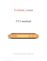
Step 2 – Setting the Sync Source
do this: Switch on the source equipment. If appropriate, load a disk / tape and set the
machine in PLAY mode to ensure it is generating a digital audio data stream.
The dCS 974 will be set to sync to the selected Audio Input and the Input
Sample Rate will be Auto detected. The unit should lock and the Unlocked
indicator should turn off. If you do not want to use an external reference clock,
proceed to Step 3.
TOP LEVEL
Sample Rate Conversion
Audio Input Select
Sync Source Audio Input Default
Multi-Channel Sync AES Loop
Input Sample Rate AES Loop Term
Wordclock
Internal
Lab Ref (10MHz)
Figure 2 – Sync Source Selection
If a stable clock source is available, you can reduce jitter in your system by
syncing to it. Choose one of the following two sections:
Syncing to an External Wordclock
If you want to synchronise your system to Wordclock from a Master Clock (such
as the dCS 992) or other stable source, do the following:
do this: Set the Master Clock sample rate to match the source (probably 44.1 or
48kS/s).
do this: Connect either a Wordclock or AES/EBU output from the Master Clock to the
clock input on the source equipment and ensure it is locked.
do this: Connect another Wordclock output from the Master Clock to the WCLK IN
connector (upper block of DSD/SDIF connectors) on the dCS 974 rear panel. Fit
a 75Ω BNC terminating plug to the nearby LOOP OUT connector.
If the source equipment uses SDIF-2 (in either PCM or DSD mode), the
Wordclock feed from the Master Clock replaces the Wordclock feed from the
source equipment.
do this: Scroll down the Sample Rate Conversion menu to Sync Source and press
the →
→→
→ button. Scroll down the list to Wordclock and press Set.
The Unlocked indicator will light for a few seconds, then turn off as the unit re-
locks.
do this: Proceed to Step 3.

dCS 974 User Manual Manual for Software Version 1.0x
dCS Ltd May 2001
Manual part no: DOC1241121A1
Page 14
Document No: OS-MA-A0124-112.1A1
Contact
dCS
on + 44 1799 531 999 email to: [email protected].uk
(inside the UK replace + 44 with 0) web site: www.dcsltd.co.uk
Syncing to an AES/EBU Reference
If you want to synchronise your system to an AES/EBU Reference from a
Master Clock (such as the dCS 992) or other stable source, do the following:
do this: Set the Master Clock sample rate to match the source (probably 44.1 or
48kS/s).
do this: Connect either an AES/EBU or Wordclock output from the Master Clock to the
clock input on the source equipment and ensure it is locked.
do this: Connect another AES/EBU output from the Master Clock to the AES Ref Loop
IN connector on the dCS 974 rear panel.
do this: Scroll down the Sample Rate Conversion menu to Sync Source and press
the →
→→
→ button. Scroll down the list to AES Loop Terminated and press Set.
The Unlocked indicator will light for a few seconds, then turn off as the unit
re-locks.
do this: Proceed to Step 3.

dCS 974 User Manual Manual for Software Version 1.0x
dCS Ltd May 2001
Manual part no: DOC1241121A1
Page 15
Document No: OS-MA-A0124-112.1A1
Contact
dCS
on + 44 1799 531 999 email to: [email protected].uk
(inside the UK replace + 44 with 0) web site: www.dcsltd.co.uk
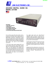
Step 3 - Setting a Conversion
do this: If you need bit-for-bit operation in a different output format, proceed to the
Format Conversion section.
do this: If you want to change the sample rate or the word length or process the data in
some other way, proceed to the Sample Rate Conversion section.
Format Conversion
TOP LEVEL
Format Conversion
Pure Format Conversion Off Default
Audio Input Select On
Sync Source
Multi-Channel Sync
Input Sample Rate
Output Mode Normal Default
Display Customise Dual AES
Quad AES
DSD SDIF-2
DSD SDIF-3
Figure 3 – Pure Format Conversion
do this: Press the ←
←←
← button, scroll down to Format Conversion , press the →
→→
→ button
and press the Set button. This sets Pure Format Conversion to On and
disables the Sample Rate Conversion menu.
do this: If the “Fs In not Fs Out” information box appears on the display, press the Set
button to make the Output Sample Rate match the Input Sample Rate.
do this: Scroll down the Format Conversion menu to Output Mode and press the →
→→
→
button. The cursor should be beside Normal. Choose one of the settings from
the following list, scroll to it and press Set:
• Normal. The Input & Output Sample Rate must not be higher than
96kS/s. Bit-for-bit data will be available on all of the AES, SPDIF or SDIF-2
outputs.
• Dual AES. The Input & Output Sample Rate must be 88.2, 96, 176.4 or
192kS/s. Dual AES bit-for-bit data will be available on the AES 1 / AES 2
output pair and the AES 3 / AES 4 output pair. Do not use the other outputs.
• Quad AES. The Input & Output Sample Rate must be 176.4 or 192kS/s.
Quad AES bit-for-bit data will be available on the AES 1, AES 2, AES 3 and
AES 4 output group. Do not use the other outputs.
• DSD SDIF-2. The Audio Input Select setting must be DSD or DSD Quad.
DSD SDIF-2 bit-for-bit data will be available from the DSD/SDIF outputs
(lower block) and DSD Quad data from the AES 1, AES 2, AES 3 and AES
4 output group. Do not use the other outputs.
• DSD SDIF-3. The Audio Input Select setting must be DSD or DSD Quad.
DSD SDIF-3 bit-for-bit data will be available from the DSD/SDIF outputs
(lower block) and DSD Quad data from the AES 1, AES 2, AES 3 and AES
4 output group. Do not use the other outputs.
do this: Proceed to Step 4.

dCS 974 User Manual Manual for Software Version 1.0x
dCS Ltd May 2001
Manual part no: DOC1241121A1
Page 16
Document No: OS-MA-A0124-112.1A1
Contact
dCS
on + 44 1799 531 999 email to: [email protected].uk
(inside the UK replace + 44 with 0) web site: www.dcsltd.co.uk
Sample Rate Conversion
TOP LEVEL
Sample Rate Conversion
Audio Input Select 192kS/s
Sync Source 176.4kS/s
Multi-Channel Sync ...
Input Sample Rate 12kS/s
Output Sample Rate 11.025kS/s
DSD Clock (DSD only)
Output Mode Normal Default
Filter Dual AES
Quad AES
DSD SDIF-2
DSD SDIF-3
Figure 4 – Sample Rate Conversion
do this: If DSD output formats are required, proceed to Setting the Output Mode.
Setting the Output Sample Rate
do this: If PCM outputs are required, scroll down the Sample Rate Conversion menu
to Output Sample Rate and press the →
→→
→ button. Scroll down the list to the
required rate and press the Set button.
If the selected conversion can be handled in one pass, the setting will be
accepted and the screen will change back to the Sample Rate Conversion
menu. If not, this information box will appear on the display:
do this: Press any button to display a list of valid output sample rates. Scroll down the
list to a suitable rate and press the Set button.

dCS 974 User Manual Manual for Software Version 1.0x
dCS Ltd May 2001
Manual part no: DOC1241121A1
Page 17
Document No: OS-MA-A0124-112.1A1
Contact
dCS
on + 44 1799 531 999 email to: [email protected].uk
(inside the UK replace + 44 with 0) web site: www.dcsltd.co.uk
Setting the Output mode
do this: Scroll down the Sample Rate Conversion menu to Output Mode and press
the →
→→
→ button. The cursor should be beside Normal Choose one of the settings
from the following list, scroll to it and press Set:
• Normal. The Output Sample Rate must not be higher than 96kS/s. Single
wire data will be available on all of the AES, SPDIF or SDIF-2 outputs.
• Dual AES. The Output Sample Rate must be 88.2, 96, 176.4 or 192kS/s.
Dual AES data will be available on the AES 1 / AES 2 output pair and the
AES 3 / AES 4 output pair. Do not use the other outputs.
• Quad AES. The Output Sample Rate must be 176.4 or 192kS/s. Quad
AES data will be available on the AES 1, AES 2, AES 3 and AES 4 output
group. Do not use the other outputs.
• DSD SDIF-2. The input format must be DSD, DSD Quad or PCM at
44.1kS/s or more. DSD SDIF-2 data will be available from the DSD/SDIF
outputs (lower block) and DSD Quad data from the AES 1, AES 2, AES 3
and AES 4 output group. Do not use the other outputs.
• DSD SDIF-3. The input format must be DSD, DSD Quad or PCM at
44.1kS/s or more. DSD SDIF-2 data will be available from the DSD/SDIF
outputs (lower block) and DSD Quad data from the AES 1, AES 2, AES 3
and AES 4 output group. Do not use the other outputs.
do this: Proceed to Step 4.

dCS 974 User Manual Manual for Software Version 1.0x
dCS Ltd May 2001
Manual part no: DOC1241121A1
Page 18
Document No: OS-MA-A0124-112.1A1
Contact
dCS
on + 44 1799 531 999 email to: [email protected].uk
(inside the UK replace + 44 with 0) web site: www.dcsltd.co.uk
Step 4 – Connecting the Outputs
Choose one of the following five sections:
Connecting a Single AES or SPDIF Output
do this: If the Output Sample Rate is 88.2 or 96kS/s, check that your destination
equipment is capable of double speed operation.
do this: If you have set Output Mode to Normal, connect the required single wire
output on the dCS 974 rear panel to the matching inputs on the destination
equipment using suitable cables. Signals are available from any of the four
AES/EBU outputs or the three SPDIF outputs simultaneously.
Connecting the SDIF-2 Output
do this: If the Output Sample Rate is 88.2 or 96kS/s, check that your destination
equipment is capable of double speed operation.
do this: If you have set Output Mode to Normal, connect the lower block of DSD/SDIF
connectors on the dCS 974 rear panel to the destination equipment using 3 coax
cables. Connect CH1 OUT to CH1 in, CH2 OUT to CH2 in and WCLK OUT to
CLK in.
Connecting the Dual AES Outputs
do this: Check that your destination equipment is capable of Dual AES operation.
do this: If you have set Output Mode to Dual AES, connect the AES 1 output on the
dCS 974 rear panel to the AES 1 (or AES A) input on the destination equipment
and the AES 2 output to the AES 2 (or AES B) input, using two XLR cables.
Ensure the cables are not swapped. An identical Dual AES pair is available
from the AES 3 and AES 4 outputs.
Connecting the Quad AES or DSD Quad Outputs
do this: Check that your destination equipment is capable of Quad AES or DSD Quad
operation.
do this: If you have set Output Mode to Quad AES or DSD Quad, connect the AES 1
output on the dCS 974 rear panel to the AES 1 input on the destination
equipment, the AES 2 output to the AES 2 input, the AES 3 output to the AES 3
input and the AES 4 output to the AES 4 input, using four XLR cables. Ensure
the cables are not swapped.
Connecting the DSD SDIF-2 or DSD SDIF-3 Output
do this: Check that your destination equipment is capable of DSD operation.
do this: If you have set Output Mode to DSD SDIF-2 or DSD SDIF-3, connect the lower
block of DSD/SDIF connectors on the dCS 974 rear panel to the destination
equipment using three coax cables. Connect CH1 OUT to CH1 in, CH2 OUT to
CH2 in and WCLK OUT to CLK in.
Note that the default setting for the DSD output clock is 44.1kS/s Wordclock
(rather than Bit clock at 2.82MS/s).
do this: Proceed to Step 5.

dCS 974 User Manual Manual for Software Version 1.0x
dCS Ltd May 2001
Manual part no: DOC1241121A1
Page 19
Document No: OS-MA-A0124-112.1A1
Contact
dCS
on + 44 1799 531 999 email to: [email protected].uk
(inside the UK replace + 44 with 0) web site: www.dcsltd.co.uk
Step 5 – Reducing the Output Wordlength
If you are using Pure Format Conversion or DSD output modes, the Output
Wordlength cannot be changed. Proceed to Other Settings.
If you are performing a sample rate conversion with PCM outputs, the
destination equipment can handle 24 bit data and you do not want to reduce the
wordlength then leave the Output Wordlength set to the default of 24 bits and
set Dither to Off. Proceed to Other Settings.
The dCS 974 generates 24 bit data, regardless of the input word length. If the
destination equipment cannot handle 24 bit data, the Output Wordlength
MUST be set to match. Noise Shaping and/or Dither MUST be applied to
smooth the transitions. If the extra bits are just ignored, the audio outputs may
sound grainy and unpleasant low effects will result. For more information, see
Word Length Reduction on page 104.
do this: Check the maximum input wordlength specification in the manual for the
destination equipment. You must set the dCS 974 to match this.
TOP LEVEL
Sample Rate Conversion
Audio Input Select
Sync Source
Multi-Channel Sync
Input Sample Rate 24 Default
Output Sample Rate 23
Output Mode ...
Filter 8
Output Wordlength
Noise Shaping Off Default
Dither 1st Order
AES Message Edit ...
10th Order
Off Default
Top Hat
Triangular
NS Triangular
Figure 5 – Setting Wordlength, Noise Shaping and Dither
do this: Scroll down the Sample Rate Conversion menu to Output Wordlength and
press the →
→→
→ button. Scroll down the list to the required number of output bits
and press Set.
do this: Scroll down the Sample Rate Conversion menu to Noise Shaping and press
the →
→→
→ button. From the list below, choose a suitable setting to match the
Output Wordlength:
• for 22 or 23 bits, scroll to 2nd order and press Set.
• for 20 or 21 bits, scroll to 3rd order and press Set.
• for 16, 17, 18 or 19 bits, scroll to 9th order and press Set.
do this: For 16 or 17 bits, scroll down the Sample Rate Conversion menu to Dither
and press the →
→→
→ button. Scroll down to NS Triangular and press Set.

dCS 974 User Manual Manual for Software Version 1.0x
dCS Ltd May 2001
Manual part no: DOC1241121A1
Page 20
Document No: OS-MA-A0124-112.1A1
Contact
dCS
on + 44 1799 531 999 email to: [email protected].uk
(inside the UK replace + 44 with 0) web site: www.dcsltd.co.uk
A wide variety of Noise Shaping and Dither setting combinations are possible.
For more information, see Word Length Reduction on page 104.
do this: Proceed to Other Settings.
/