Page is loading ...

Flex Mini System
Radio Control Equipment
Instruction Manual
191-75020-0001 R07
April 2019
© Copyright 2019 Magnetek Material Handling

Flex Mini System Instruction Manual
April 2019
Page 2 of 28
SERVICE CONTACT INFORMATION
Your New Radio Remote Control System
Thank you for your purchase of Magnetek’s Flex Mini radio remote control system. Without a doubt,
our Flex Mini system is the ultimate solution for providing precise, undeterred, and safe control of your
material.
If your product ever needs modification or service, please contact one of our representatives at the
following locations:
U.S. Service Information
For questions regarding service or technical information contact:
1-866-MAG-SERV
(1-866-624-7378)
International Service
262-783-3500
World Headquarters:
Magnetek, Inc,
N49 W13650 Campbell Drive
Menomonee Falls, WI 53051
Telephone: 800-288-8178
Website: www.magnetek.com
E-mail: mhcustomerservice@magnetek.com
Fax Numbers:
Main: 800-298-3503
Sales: 262-783-3510
Service: 262-783-3508
Canada Service Information:
161 Orenda Road
Unit 1
Brampton, Ontario
L6W 1W3 Canada
Phone: 800-792-7253
Fax: 905-828-5707
416-424-7617 (24/7 Service pager)
EU Market Contact:
Brian Preston
Magnetek (UK) Ltd.
Unit 3 Bedford Business Centre
Mile Road
Bedford, MK42 9TW UK
Phone: +44-1234-349191
©2019 MAGNETEK
All rights reserved. This notice applies to all copyrighted materials included with this product, including,
but not limited to, this manual and software embodied within the product. This manual is intended for
the sole use of the person(s) to whom it was provided, and any unauthorized distribution of the
manual or dispersal of its contents is strictly forbidden. This manual may not be reproduced in whole
or in part by any means whatsoever without the expressed written permission of MAGNETEK.

Flex Mini System Instruction Manual
April 2019
Page 3 of 28
TABLE OF CONTENTS
SERVICE INFORMATION ...................................................................................................................... 2
TABLE OF CONTENTS .......................................................................................................................... 3
1 PREFACE AND SAFETY ............................................................................................................... 5
1.1 Product Safety Information ...................................................................................................... 5
1.2 Product Warranty Information ................................................................................................. 5
2 RADIO CONTROLLED SAFETY ................................................................................................... 6
2.1 CRITICAL INSTALLATION CONSIDERATIONS..................................................................... 7
2.2 GENERAL ............................................................................................................................... 7
2.3 PERSONS AUTHORIZED TO OPERATE RADIO CONTROLLED CRANES ........................ 7
2.4 SAFETY INFORMATION AND RECOMMENDED TRAINING FOR RADIO
CONTROLLED EQUIPMENT OPERATORS ............................................................................. 7
2.5 TRANSMITTER UNIT ............................................................................................................. 8
2.6 PRE-OPERATION TEST ......................................................................................................... 9
2.7 HANDLING BATTERIES ......................................................................................................... 9
2.8 OPTIONAL RECHARGEABLE BATTERY CHARGING .......................................................... 9
2.9 BATTERY DISPOSAL ............................................................................................................. 9
2.10 CRANE/LIFTING DEVICE SPECIFIC WARNINGS .............................................................. 10
2.11 SPECIFIC SYSTEM WARNINGS ......................................................................................... 10
3 GENERAL SYSTEM INFORMATION .......................................................................................... 11
3.1 TRANSMITTER ..................................................................................................................... 11
3.1.1 External Illustration ........................................................................................................ 11
3.1.2 Internal Illustration ......................................................................................................... 12
3.2 RECEIVER ............................................................................................................................ 13
3.2.1 External Illustration ........................................................................................................ 13
3.2.2 Internal Illustration ......................................................................................................... 14
4 FUNCTION SETTINGS ................................................................................................................ 15
4.1 TRANSMITTER ..................................................................................................................... 15
4.1.1 Channel Settings ........................................................................................................... 15
4.1.2 Keypad Type Settings ................................................................................................... 16
4.1.3 Transmitter Inactivity/Sleep Timer Settings ................................................................... 17
4.1.4 Remote Pairing .............................................................................................................. 17
4.2 RECEIVER ............................................................................................................................ 19
4.2.1 Dipswitch Settings ......................................................................................................... 19
4.2.2 Jumper Settings (for units with the external Pairing button) ......................................... 20
4.2.3 External Programming (for units with the external Pairing button) ............................... 20
4.2.4 Fuse Ratings ................................................................................................................. 20
4.2.5 Using External Antenna (optional)................................................................................. 21
5 RECEIVER INSTALLATION ........................................................................................................ 22
6 OPERATING PROCEDURE ........................................................................................................ 25
6.1 GENERAL OPERATING PROCEDURE ............................................................................... 25
6.2 CHANGING TRANSMITTER BATTERIES ........................................................................... 25
7 STATUS AND WARNINGS .......................................................................................................... 26

Flex Mini System Instruction Manual
April 2019
Page 4 of 28
7.1 TRANSMITTER STATUS LIGHT INDICATIONS .................................................................. 26
7.2 RECEIVER STATUS LIGHT INDICATIONS.......................................................................... 26
7.3 RECEIVER COM LIGHT INDICATIONS ............................................................................... 26
7.4 RECEIVER POWER LIGHT INDICATIONS .......................................................................... 26
8 SYSTEM SPECIFICATIONS ........................................................................................................ 27
9 DECLARATION OF CONFORMITY ............................................................................................ 28

Flex Mini System Instruction Manual
April 2019
Page 5 of 28
1 PREFACE AND SAFETY
©2016 MAGNETEK
All rights reserved. This notice applies to all copyrighted materials included with this product,
including, but not limited to, this manual. This manual is intended for the sole use of the persons to
whom it was provided, and any unauthorized distribution of the manual or dispersal of its contents is
strictly forbidden. This manual may not be reproduced in whole or in part by any means whatsoever
without the expressed written permission of Magnetek.
1.1 Product Safety Information
Magnetek, Inc. (Magnetek) offers a broad range of radio remote control products, control products and
adjustable frequency drives, and industrial braking systems for material handling applications. This
manual has been prepared by Magnetek to provide information and recommendations for the
installation, use, operation and service of Magnetek’s material handling products and systems
(Magnetek Products). Anyone who uses, operates, maintains, services, installs or owns Magnetek
Products should know, understand and follow the instructions and safety recommendations in this
manual for Magnetek Products.
The recommendations in this manual do not take precedence over any of the following requirements
relating to cranes, hoists lifting devices or other material handling equipment which use or include
Magnetek Products:
• Instructions, manuals, and safety warnings of the manufacturers of the equipment where the
radio system is used,
• Plant safety rules and procedures of the employers and the owners of facilities where the
Magnetek Products are being used,
• Regulations issued by the Occupational Health and Safety Administration (OSHA),
• Applicable local, state or federal codes, ordinances, standards and requirements, or
• Safety standards and practices for the industries in which Magnetek Products are used.
This manual does not include or address the specific instructions and safety warnings of these
manufacturers or any of the other requirements listed above. It is the responsibility of the owners,
users and operators of the Magnetek Products to know, understand and follow all of these requirements.
It is the responsibility of the employer to make its employees aware of all of the above listed
requirements and to make certain that all operators are properly trained. No one should use
Magnetek Products prior to becoming familiar with and being trained in these requirements and
the instructions and safety recommendations in this manual.
1.2 Product Warranty Information
Magnetek, hereafter referred to as Company, assumes no responsibility for improper programming of
a device (such as a drive or radio) by untrained personnel. A device should only be programmed by a
trained technician who has read and understands the contents of the relevant manual(s). Improper
programming of a device can lead to unexpected, undesirable, or unsafe operation or performance of
the device. This may result in damage to equipment or personal injury. Company shall not be liable
for economic loss, property damage, or other consequential damages or physical injury sustained by
the purchaser or by any third party as a result of such programming. Company neither assumes nor
authorizes any other person to assume for Company any other liability in connection with the sale or
use of this product.
For information on Magnetek’s product warranties by product type, please visit www.magnetek.com.

Flex Mini System Instruction Manual
April 2019
Page 6 of 28
2 RADIO CONTROLLED SAFETY
WARNINGS and CAUTIONS
Throughout this document WARNING and CAUTION statements have been deliberately placed to highlight
items critical to the protection of personnel and equipment.
WARNING – A warning highlights an essential operating or maintenance procedure, practice, etc.
which if not strictly observed, could result in injury or death of personnel, or long term physical
hazards. Warnings are highlighted as shown below:
WARNING
CAUTION – A caution highlights an essential operating or maintenance procedure, practice, etc.
which, if not strictly observed, could result in damage to or destruction of equipment, or loss of
functional effectiveness. Cautions are highlighted as shown below:
CAUTION
WARNINGS and CAUTIONS SHOULD NEVER BE DISREGARDED.
The safety rules in this section are not intended to replace any rules or regulations of any applicable local,
state, or federal governing organizations. Always follow your local lockout and tagout procedure when
maintaining any radio equipment. The following information is intended to be used in conjunction with other
rules or regulations already in existence. It is important to read all of the safety information contained in this
section before installing or operating the Radio Control System.

Flex Mini System Instruction Manual
April 2019
Page 7 of 28
2.1 CRITICAL INSTALLATION CONSIDERATIONS
WARNING
PRIOR TO INSTALLATION AND OPERATION OF THIS EQUIPMENT, READ AND DEVELOP AN
UNDERSTANDING OF THE CONTENTS OF THIS MANUAL AND THE OPERATION MANUAL OF THE
EQUIPMENT OR DEVICE TO WHICH THIS EQUIPMENT WILL BE INTERFACED. FAILURE TO FOLLOW
THIS WARNING COULD RESULT IN SERIOUS INJURY OR DEATH AND DAMAGE TO EQUIPMENT.
FOLLOW YOUR LOCAL LOCKOUT TAGOUT PROCEDURE BEFORE MAINTAINING ANY REMOTE
CONTROLLED EQUIPMENT. ALWAYS REMOVE ALL ELECTRICAL POWER FROM THE EQUIPMENT
BEFORE ATTEMPTING ANY INSTALLATION PROCEDURES. DE-ENERGIZE AND TAGOUT ALL SOURCES
OF ELECTRICAL POWER BEFORE TOUCH-TESTING ANY EQUIPMENT. FAILURE TO FOLLOW THIS
WARNING COULD RESULT IN SERIOUS INJURY OR DEATH AND DAMAGE TO EQUIPMENT.
AFTER INSTALLATION BE SURE TO VERIFY THAT THE TRANSMITTER IS NOT INTERFERING WITH
OTHER EQUIPMENT IN THE AREA. ALSO VERIFY THAT OTHER EQUIPMENT IS NOT INTERFERING
WITH THE TRANSMITTER AND ITS ASSOCIATED EQUIPMENT. FAILURE TO FOLLOW THESE
WARNINGS COULD RESULT IN SERIOUS INJURY OR DEATH AND DAMAGE TO EQUIPMENT.
2.2 GENERAL
Radio controlled equipment operates in several directions. Quite frequently, the equipment is operated in areas
where people are working in close proximity to the equipment. The operator must exercise extreme caution
at all times. Workers must constantly be alert to avoid accidents. The following recommendations have been
included to indicate how careful and thoughtful actions may prevent injuries, damage to equipment, or even
save a life.
2.3 PERSONS AUTHORIZED TO OPERATE RADIO CONTROLLED
CRANES
Only properly trained persons designated by management should be permitted to operate radio controlled
equipment.
Radio controlled equipment should not be operated by any person who cannot read or understand signs, notices
and operating instructions that pertain to the equipment.
Radio controlled equipment should not be operated by any person with insufficient eyesight or hearing or by any
person who may be suffering from a disorder or illness, is taking any medication that may cause loss of
equipment control, or is under the influence of alcohol or drugs.
2.4 SAFETY INFORMATION AND RECOMMENDED TRAINING FOR
RADIO CONTROLLED EQUIPMENT OPERATORS
Anyone being trained to operate radio controlled equipment should possess as a minimum the following
knowledge and skills before using the radio controlled equipment.
The operator should:
• have knowledge of hazards pertaining to equipment operation
• have knowledge of safety rules for radio controlled equipment
• have the ability to judge distance of moving objects
• know how to properly test prior to operation
• be trained in the safe operation of the radio transmitter as it pertains to the equipment being operated
• have knowledge of the use of equipment warning lights and alarms

Flex Mini System Instruction Manual
April 2019
Page 8 of 28
• have knowledge of the proper storage space for a radio control transmitter when not in use
• be trained in transferring a radio control transmitter to another person
• be trained how and when to report unsafe or unusual operating conditions
• test the transmitter emergency stop and all warning devices prior to operation; testing should be done
on each shift, without a load
• be thoroughly trained and knowledgeable in proper and safe operation of the equipment that utilizes the
radio control
• know how to keep the operator and other people clear of hazardous areas
• know and follow the local lockout and tagout procedures when servicing radio controlled equipment
• know and follow all applicable operating and maintenance manuals, safety procedures, regulatory
requirements, and industry standards and codes
The operator shall not:
• operate the equipment if the direction of travel or function engaged does not agree with what is indicated
on the controller
• operate any damaged or malfunctioning equipment
• change any settings or controls without authorization and proper training
• remove or obscure any warning or safety labels or tags
• leave power on the radio controlled equipment when the equipment is not in operation
• operate any equipment using a damaged controller because the unit may be unsafe
• operate manual motions with other than manual power
• operate radio controlled equipment when low battery indicator is on
WARNING
THE OPERATOR SHOULD NOT ATTEMPT TO REPAIR ANY RADIO CONTROLLER. IF ANY PRODUCT
PERFORMANCE OR SAFETY CONCERNS ARE OBSERVED, THE EQUIPMENT SHOULD IMMEDIATELY BE
TAKEN OUT OF SERVICE AND BE REPORTED TO THE SUPERVISOR. DAMAGED AND INOPERABLE
RADIO CONTROLLER EQUIPMENT SHOULD BE RETURNED TO MAGNETEK FOR EVALUATION AND
REPAIR. FAILURE TO FOLLOW THIS WARNING COULD RESULT IN SERIOUS INJURY OR DEATH AND
DAMAGE TO EQUIPMENT.
2.5 TRANSMITTER UNIT
Transmitter switches should never be mechanically blocked ON or OFF. When not in use, the operator should
turn the transmitter OFF. A secure storage space should be provided for the transmitter unit, and the transmitter
unit should always be placed there when not in use. This precaution will help prevent unauthorized people from
operating the material handling equipment.
Spare transmitters should be stored in a secure storage space and only removed from the storage space after
the current transmitter in use has been turned OFF, taken out of the service area and secured.

Flex Mini System Instruction Manual
April 2019
Page 9 of 28
2.6 PRE-OPERATION TEST
At the start of each work shift, or when a new operator takes control of the equipment, operators should do, as a
minimum, the following steps before making lifts with any equipment:
Test all warning devices.
Test all functions.
Test the transmitter machine stop.
2.7 HANDLING BATTERIES
WARNING
KNOW AND FOLLOW PROPER BATTERY HANDLING, CHARGING AND DISPOSAL PROCEDURES.
IMPROPER BATTERY PROCEDURES CAN CAUSE BATTERIES TO EXPLODE OR DO OTHER SERIOUS
DAMAGE. FAILURE TO FOLLOW THIS WARNING COULD RESULT IN SERIOUS INJURY OR DEATH
AND DAMAGE TO EQUIPMENT.
Use only batteries approved by Magnetek for the specific product.
Do not dispose of a battery pack in fire; it may explode.
Do not attempt to open the battery pack.
Do not short circuit the battery.
Keep the battery pack environment cool during storage (i.e., not in direct sunlight or close to a heating source).
2.8 OPTIONAL RECHARGEABLE BATTERY CHARGING
For those transmitters equipped with rechargeable batteries and battery chargers, all users shall be familiar with
the instructions of the charger before attempting to use.
Do not attempt to charge non-rechargeable battery packs in the charger.
Avoid charging partially discharged rechargeable batteries to help prolong battery cycle life.
Do not charge batteries in a hazardous environment.
Keep the battery pack environment cool during charging (i.e., not in direct sunlight or close to a heating source).
Do not short the charger.
Do not attempt to charge a damaged battery.
Use only Magnetek approved chargers for the appropriate battery pack.
Do not attempt to use a battery that is leaking, swollen or corroded.
Charger units are not intended for outdoor use. Only use charger units indoors.
2.9 BATTERY DISPOSAL
Before disposing of batteries consult local and governmental regulatory requirements for proper disposal
procedure.

Flex Mini System Instruction Manual
April 2019
Page 10 of 28
2.10 CRANE/LIFTING DEVICE SPECIFIC WARNINGS
WARNING
EQUIPMENT MUST HAVE A MAINLINE CONTACTOR INSTALLED AND ALL TRACKED CRANES, HOISTS,
LIFTING DEVICES AND SIMILAR EQUIPMENT MUST HAVE A BRAKE INSTALLED. FAILURE TO FOLLOW
THIS WARNING COULD RESULT IN SERIOUS INJURY OR DEATH AND DAMAGE TO EQUIPMENT.
AN AUDIBLE AND/OR VISUAL WARNING MEANS MUST BE PROVIDED ON ALL REMOTE CONTROLLED
EQUIPMENT AS REQUIRED BY CODE, REGULATION, OR INDUSTRY STANDARD. THESE AUDIBLE
AND/OR VISUAL WARNING DEVICES MUST MEET ALL GOVERNMENTAL REQUIREMENTS. FAILURE TO
FOLLOW THIS WARNING COULD RESULT IN SERIOUS INJURY OR DEATH AND DAMAGE TO
EQUIPMENT.
THE DIRECT OUTPUTS OF THIS PRODUCT ARE NOT DESIGNED TO INTERFACE DIRECTLY TO TWO
STATE SAFETY CRITICAL MAINTAINED FUNCTIONS, I.E., MAGNETS, VACUUM LIFTS, PUMPS,
EMERGENCY EQUIPMENT, ETC. A MECHANICALLY LOCKING INTERMEDIATE RELAY SYSTEM WITH
SEPARATE POWER CONSIDERATIONS MUST BE PROVIDED. FAILURE TO FOLLOW THIS WARNING
COULD RESULT IN SERIOUS INJURY OR DEATH OR DAMAGE TO EQUIPMENT.
Cranes, hoists, lifting devices and other material handling equipment can be large, and operate at high speeds.
The operator should:
• continuously watch and monitor status of lifted loads
• know and follow cable and hook inspection procedures
The operator shall not:
• lift or move more than the rated load
• use the crane, hoist or lifting device to lift, support or transport people
• lift or carry any loads over people
• operate the crane, hoist or lifting device unless all persons, including the operator, are and remain clear
of the supported load and any potential pinch points
• operate a crane, hoist or lifting device when the device is not centered over the load
• operate a crane, hoist or lifting device if the chain or wire rope is not seated properly in the sprockets,
drum or sheave
• leave any load unattended while lifted
2.11 SPECIFIC SYSTEM WARNINGS
Below are some specific operating safety tips that should be strictly followed when operating a Flex Mini system:
1. Check the Status LED on the transmitter for any signs of low battery power.
2. Check the Status LED on the transmitter for any signs of irregularities.
3. Make sure the system is not set to the same channel as any other Flex Mini systems in use within a
distance of 300 meters (900 feet).
4. Never operate equipment with two transmitter handsets at the same time unless they are programmed
to do so.

Flex Mini System Instruction Manual
April 2019
Page 11 of 28
2
4
6
8
9
1
3
5
7
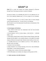
3 GENERAL SYSTEM INFORMATION
3.1 TRANSMITTER
3.1.1 External Illustration
1. Button #1 (PB1)
6. Button #6 (PB6)
2. Button #2 (PB2)
7. Button #7 (PB7)
3. Button #3 (PB3)
8. Button #8 (PB8)
4. Button #4 (PB4)
9. Status LED
5. Button #5 (PB5)

Flex Mini System Instruction Manual
April 2019
Page 12 of 28
2
4
6
8
9
1
3
5
7
10
12
11
13
3.1.2 Internal Illustration
1. Button #1 (PB1)
8. Button #8 (PB8)
2. Button #2 (PB2)
9. Status LED
3. Button #3 (PB3)
10. RF + Encoder Board
4. Button #4 (PB4)
11. Function Dip-switch
5. Button #5 (PB5)
12. Programming Port
6. Button #6 (PB6)
13. Battery Contacts
7. Button #7 (PB7)

Flex Mini System Instruction Manual
April 2019
Page 13 of 28
3.2 RECEIVER
3.2.1 External Illustration
1. COM LED
5. Output Relays LED
2. Status LED
6. System Information
3. Power LED
7. Cord Grip
4. External Antenna Jack
8. Mounting Bracket
8

Flex Mini System Instruction Manual
April 2019
Page 14 of 28
3.2.2 Internal Illustration
1. RF + Decoder Board
2. AC Line Filter + Relay Board
3. Power Transformer

Flex Mini System Instruction Manual
April 2019
Page 15 of 28
4 FUNCTION SETTINGS
4.1 TRANSMITTER
4.1.1 Channel Settings
Enter the transmitter function setting mode by moving the function dip-switch located inside the
battery compartment to the “on” position. Reinsert the two batteries and press PB1 to power up the
transmitter. At this point the Status LED will display a series of red, green, and orange blinks showing
the current software version. Then press and hold PB3 for up to 1.0 second to go into the transmitter
channel setting mode. At this point the Status LED will display a series of green and red blinks
showing the current system channel. A green blink represents the tens (+10) and a red blink
represents the units (+1). For example, one (1) green blink followed by five (5) red blinks is channel
15.
Now select a new channel by pressing PB1 and PB2 on the transmitter. Press PB1 to increment the
units (+1) and PB2 to increment the tens (+10). For example, pressing PB2 two times and then PB1
four times will set the transmitter to channel 24.
NOTE: When selecting a new channel, make sure each button press does not exceed 3.0 seconds.
When finished the transmitter Status LED will display the newly selected channel. The newly selected
channel must be transferred to the receiver by pressing and holding PB3 for up to 10.0 seconds or
until the transmitter Status LED turns off, which indicates that the transferring process is completed.
Make sure the receiver power is turned on during the process. Exit the transmitter function setting
mode by removing the batteries and moving the function dip-switch back to the “Off” position.
NOTE: When the transmitter keypad is set to type 1 the receiver must be reset (turned off and back
on), or the channel setting process must be executed 10 minutes after receiver inactivity.
NOTE: When you are changing the transmitter channel you must also change the receiver channel at
the same time prior to exiting the transmitter function setting mode (see the instructions above). If you
exit the transmitter function setting mode without pressing PB3 for up to 10.0 seconds to transfer the
newly selected channel to the receiver, you will have to change the newly selected transmitter
channel back to its previous setting. This can be done by reentering the transmitter function setting
mode and then pressing and holding PB1 and PB3 at the same time for up to 2.0 seconds; this will
reset the newly selected channel back to the previous setting.
Alternately, perform the remote pairing process (RX to TX) described in Section 4.1.4 Remote Pairing;
this will transfer the receiver channel to the transmitter. Repeat the channel setting process again if
you would like to reselect a new channel.

Flex Mini System Instruction Manual
April 2019
Page 16 of 28
PB3PB4
PB5PB6
PB8 PB7
PB2
Type 1
PB1
PB3PB4
PB5PB6
PB8 PB7
PB2
ON
OFF
Type 2
PB3PB4
PB5PB6
PB8 PB7
START
Type 3
STOP
4.1.2 Keypad Type Settings
Enter the transmitter function setting mode by moving the function dip-switch located inside the
battery compartment to the “on” position. Reinsert the two batteries and press PB1 to power up the
transmitter. At this point the Status LED will display a series of red, green, and orange blinks showing
the current software version. Press and hold PB4 for up to 1.0 second to go into the keypad type
setting mode. At this point the Status LED will blink red, showing the current keypad type. A green
blink represents the tens (+10) and a red blink represents the units (+1). For example, two (2) red
blinks is keypad type 2.
Now select the new keypad type by pressing PB1 and PB2 on the transmitter. Press PB1 to
increment the units (+1) and PB2 to increment the tens (+10). For example, press PB1 two times for
keypad type 2 and three times for keypad type 3. The Status LED will display the newly selected
keypad type when finished. Exit transmitter function setting mode by taking out the batteries and
moving the function dip-switch back to the “Off” position.
NOTE: When selecting a new keypad type, make sure each button press does not exceed 3.0
seconds.
4.1.2.1 Keypad Overlay
When changing the keypad type setting, it is recommended to change the keypad overlay sticker on
the unit as well. This will ensure that the operator knows which buttons are the function buttons and
which buttons are used for either ON/OFF or START and STOP. The following procedure should be
used to change the keypad overlay. If the unit does not have an overlay, start at step 4.
1. Remove the old overlay.
2. Wipe the unit down with rubbing alcohol to remove any adhesive that is still on the unit.
3. Let the unit dry.
4. Remove the backing from the new overlay.
5. Align the overlay with the bottom of the inset for the keypad.
6. Slowly place the overlay over the buttons ensuring that the overlay makes contact around
each of the buttons.
7. Firmly press the entire overlay to ensure that it seals the unit to maintain sealing.

Flex Mini System Instruction Manual
April 2019
Page 17 of 28
PB3
PB4
4.1.3 Transmitter Inactivity/Sleep Timer Settings
After entering the transmitter function setting mode, press and hold both PB2 and PB4 at the same
time for up to 1 second (Status LED orange) and then let go (Status LED displays current sleep timer
setting). A green blink represents the tens (+10), a red blink represents the units (+1) and an orange
blink represents constant ON (sleep mode disabled). For example, one (1) green blink followed by five
(5) red blinks is 15 minutes. By default the sleep timer is set to 5 minutes.
Select new timer value by pressing PB1, PB2, or PB3+PB4 on the transmitter. Press PB1 to
increment the units (+1), PB2 to increment the tens (+10), and PB3+PB4 to constant ON (sleep mode
disabled). For example, press PB2 two times and then PB1 four times to set the timer value for 24
minutes. Make sure each button press is executed within 3 seconds. The timer value available for
programming is 1~60 minutes and constant ON (sleep mode disabled). When finished, the transmitter
Status LED will display the newly selected sleep timer value. Exit the transmitter function setting mode
by removing the batteries and moving the function dipswitch back to the “Off” position.
4.1.4 Remote Pairing
Enter the transmitter function setting mode by moving the function dip-switch
located inside the battery compartment to the “On” position. Reinsert the two
batteries and press PB1 to power up the transmitter. At this point the Status
LED will display a series of red, green, and orange blinks showing the current
software version. Then press and hold PB3 and PB4 at the same time for up
to 1.0 second to go into the remote pairing mode (Status LED orange and then
off).
TX to TX Pairing:
→
Output data – original transmitter Receiving data – new transmitter
(Press and hold PB3) (Press and hold PB4)
After entering the remote pairing mode, output data by pressing and holding PB3 on the original
transmitter and receive data to the new transmitter by pressing and holding PB4 at the same time.
The pairing is completed when the Status LED on the new transmitter (the unit receiving the data)
turns to constant green while the buttons are still pressed down. Exit the transmitter function setting
mode by taking out the batteries and move the function dipswitch on both transmitters back to the
“Off” position.

Flex Mini System Instruction Manual
April 2019
Page 18 of 28
PB4
JP1
JP2
JP1
JP2
PB4
RX to TX Pairing:
→
Output data - receiver Receiving data – transmitter
(Press and hold PB1) (Press and hold PB4)
Via the Decoder Board
JP1 Open Method (via the decoder board): After entering the remote pairing mode, output receiver
data by pressing and holding PB1 located on the decoder board and receive data by pressing and
holding PB4 on the transmitter at the same time. The pairing is completed when the transmitter
Status LED turns to constant green while both buttons are still pressed down. Exit the transmitter
function setting mode by taking the batteries out of the transmitter and move the function dipswitch
back to the “Off” position.
→
Output data - receiver Receiving data – transmitter
(Press and hold the Pairing button) (Press and hold PB4)
Via the External Pairing Button
JP1 Open Method (via the external Pairing button): After entering the remote pairing mode, output
receiver data by pressing and holding the Pairing button located on the receiver cover and receive
data by pressing and holding PB4 on the transmitter at the same time. The pairing is completed when
the transmitter Status LED turns to constant green while both buttons are still pressed down. Exit the
transmitter function setting mode by taking the batteries out of the transmitter and move the function
dipswitch back to the “Off” position.
JP1 Short Method (does not require the decoder board or the external Pairing button): After
entering the remote pairing mode, press PB1 on the transmitter and then press and hold PB3 for up to
5.0 seconds to activate receiver data output mode (Status LED green blinks). Then press and hold
PB4 on the transmitter until the Status LED turns to constant green (RX to TX pairing complete). Exit
the transmitter function setting mode by taking the batteries out of the transmitter and move the
function dip-switch back to the “Off” position. Make sure the RX to TX pairing process is executed
within a distance of 10 meters from one another.
NOTE: When the transmitter keypad is set to type 1 while performing RX to TX remote pairing, the
receiver must be reset (turn off and back on) or the RX to TX remote pairing must be executed 5
minutes after receiver inactivity.

Flex Mini System Instruction Manual
April 2019
Page 19 of 28
ON
1 2 3 4 5 6 7 8
ON
1 2 3 4 5 6 7 8
4.2 RECEIVER
4.2.1 Dipswitch Settings
Top position → “1”
Bottom position → “0”
Dipswitch #1 (right):
Position Dip 1 Dip 2 Dip 3 Dip 4 Dip 5 Dip 6 Dip 7 Dip 8
Set to “0”
PB1
Normal
PB2
Normal
PB3
Normal
PB4
Normal
PB5
Normal
PB6
Normal
PB7
Normal
PB8
Normal
Set to “1”
PB1
Toggled
PB2
Toggled
PB3
Toggled
PB4
Toggled
PB5
Toggled
PB6
Toggled
PB7
Toggled
PB8
Toggled
Toggled functions maintain contact when transmitter power is turned off (keypad type 2) or Stop button is pressed (keypad type 3).
Dipswitch #2 (left):
Position Dip 1 Dip 2 Dip 3 Dip 4 Dip 5 Dip 6 Dip 7 Dip 8
Set to “1”
PB1&2
On & Off
PB3&4
On & Off
PB5&6
On & Off
PB7&8
On & Off
PB1&2
Interlocked
PB3&4
Interlocked
PB5&6
Interlocked
PB7&8
Interlocked
Set to “0”: According to dip-switch #1 setting.
Dip 5~8 set to “1”: Button pair interlocked. When set to interlocked pair you must reconfigure dip-switch #1 below.
On & Off function turns to “Off” when transmitter power is turned off (keypad type 2) or Stop button is pressed (keypad type 3).
Dipswitch #1 (right) - Normal and Toggled Interlocked Settings:
Position Dip 1&2 Dip 3&4 Dip 5&6 Dip 7&8
Set to “00”
PB1&2 Normal/Normal
Interlocked
PB3&4 Normal/Normal
Interlocked
PB5&6 Normal/Normal
Interlocked
PB7&8 Normal/Normal
Interlocked
Set to “01”
PB1&2 Toggled/Toggled
Interlocked
PB3&4 Toggled/Toggled
Interlocked
PB5&6 Toggled/Toggled
Interlocked
PB7&8 Toggled/Toggled
Interlocked
Dipswitch #2 (left) - ID Function Settings (keypad type 3):
Position Function Position Function
Set to “0001001”
K2 output relay closes when
PB7 & PB8 is pressed.
Set to “0001101”
K2 output relay closes when
PB3 & PB4 or PB7 & PB8 is pressed.
Set to “0001010”
K2 output relay closes when
PB5 & PB6 is pressed.
Set to “0001110”
K2 output relay closes when
PB3 ~ PB6 is pressed.
Set to “0001011”
K2 output relay closes when
PB5 ~ PB8 is pressed.
Set to “0001111”
K2 output relay closes when
PB3 ~ PB8 is pressed.
Set to “0001100”
K2 output relay closes when
PB3 & PB4 is pressed.
When a button pair is set to the ID function the corresponding button setting on dipswitch #1 must set to “0”.
When set to ID function the START/AUX function on keypad type 3 is disabled (auxiliary function replaced by ID function).

Flex Mini System Instruction Manual
April 2019
Page 20 of 28
4.2.2 Jumper Settings (for units with the external Pairing
button)
JP1 Open → Remote pairing function (press Pairing button required).
JP1 Short → Remote pairing function (press Pairing button not required).
JP2 Open → System normal.
JP2 Short → Display receiver software version.
JP3 Open → Normal toggled function set on the dip-switches.
JP3 Short → All toggled functions set on the dip-switches deactivates
when shutting off the transmitter power (keypad type 2)
and when the Stop button is pressed (keypad type 3).
JP4 ~ JP8 → Reserved for future functions.
4.2.3 External Programming (for units with the external
Pairing button)
Other settings not listed in this manual can be programmed via the external programmer unit. Please
contact Magnetek representatives in your area for more details.
Transmitter Receiver
Other available functions set via external programmer unit:
1) On & Off function not affected by the transmitter power On/Off and Stop command.
2) On + Start / Off + Start function (keypad type 3 only).
4.2.4 Fuse Ratings
Fuse # 110~120VAC 220~240VAC 380~400VAC 410~460VAC 24VAC 42 & 48VAC 9~36VDC
F2 & F3 5.0A 5.0A 5.0A 5.0A 5.0A 5.0A 5.0A
F1 0.5A 0.5A 0.5A 0.5A 1.0A 1.0A 2.0A
/