BE365

Schlage BE365 Installation guide

  • Hello! I am an AI chatbot trained to assist you with the Schlage BE365 Installation guide. I’ve already reviewed the document and can help you find the information you need or explain it in simple terms. Just ask your questions, and providing more details will help me assist you more effectively!
Installation Instructions
BE365
P515-481
A. Keypad Assembly
B. Deadbolt
C. Mounting Plate
D. 9V Battery
E. Mounting Screws
F. Thumbturn Assembly
G. Thumbturn Screws
H. Deadbolt/Strike Screws
J. Strike
K. Dust Box
L. Reinforcement Screws
M. Reinforcement Plate
N. Rounded-corner Faceplate
P. Square-corner Faceplate
Q. Drive-in Faceplate
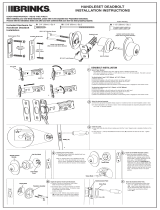
Install Lock
Remove Template From Programming Booklet
1
OR
Tools for Installation
E
D
F
B
C
A
H
G
J
K
L
M
2
Check Door Holes
Note: If door holes do not match template, visit
www.schlage.com for door drilling instructions.
Q
P
N
2
A.
K
e
y
1
.
T
ur
ns on the ba
cklight.
2
.
Indicates lo
c
k status
(
pro
gr
amming
mode
,
l
ow batte
r
y
,
etc.)
and success
or
f
ailure of an ope
r
ation.
3
.
Con
r
ms a men
u ent
r
y dur
ing
pro
gr
amming (see page 8)
.
4
.
U
sed to
e
xit pro
gr
amming or to clear
an incorrect ent
r
y
.
B
.
K
eyp
a
d
1
.
U
sed to unlo
c
k the lo
c
k
b
y ente
r
ing a
v
alid
f
our-digit user cod
e.
2
.
U
sed to progr
am the lo
c
k
.
(
See page
8.)
C
.
K
e
y
Overri
de
(
S
ee
p
a
g
e
11
.
)
U
sed to unlo
c
k the lo
c
k in the f
oll
o
wing
situations:
1
. Lo
c
k has
f
ailed electronicall
y
.
2
.
Batte
r
y is dead.
3.
U
ser code is not known.
D
.
O
utsi
de
K
no
b
/
L
eve
r
T
o minimi
z
e damage from
v
andalism
,
the outside knob/l
e
v
er rotates
but does
not retr
act latch
e
v
en when loc
k is
lo
ck
ed.
E
.
Insi
de
K
no
b
/
L
eve
r
The inside knob/l
ev
er is al
w
a
ys
unlock
ed
f
or immediate e
xit.
F
E575
Fe
atur
es
A.
K
e
y
B.
K
e
ypad
C
.
K
e
y
O
v
er
r
ide
D
.
O
utside Knob/L
e
v
er
E
.
I
nside Knob/L
e
v
er
2
³⁄₈
(6
0
m
m
)
T
o
D
o
o
r Edge
C
U
T H
E
R
E
2
³⁄₄
” (7
0
mm
)
T
o D
o
o
r E
dge
1⁵⁄
"
For
1
³⁄₈
"
Th
i
ck
Do
o
r
For
1
³⁄₄
"
Thick Door
⁷⁄₈
(22
m
m
)
Hol
e
Template f
or FE
575
, FE59
5
,
BE3
65
Fo
r
U
se
With
O
R
2¹⁄₈
(54
mm
)
H
ole
O
R
Match to
Door Ed
ge
D
oor
Edg
e
2
³⁄₈
or 2
³⁄₄
R
o
t
a
t
e
T
e
m
p
l
a
t
e
t
o
M
a
t
c
h
D
o
o
r
5¹⁄₂
Minimum
2
³
⁄₈
” (
6
0
m
m
)
T
o
D
oor
E
d
g
e
R
o
t
a
t
e
T
e
m
p
l
a
t
e
t
o
M
a
t
c
h
D
o
o
r
2
³
⁄₄” (7 0
m
m
)
To
D
oor
E
d
g
e
O
R
2
¹⁄₈
(54 m
m
)
H
o
le
2³⁄₈
o
r 2
³⁄₄
D
oor E
d
g
e
Te m
pla
te for
FE575, FE59
5
,
BE
3
65
F
o
r
1
³⁄₈
"
T
hi
c
k
Do
o
r
Fo
r
1
³⁄₄"
T
hi
c
k
D
o
o
r
1
⁵⁄
"
⁷⁄₈
(22
m
m
)
H
o
le
F
or
U
se
W
ith
OR
M
a
tch t
o
D
oo
r
E
d
g
e
CUT HERE
Keep the programming
booklet with you while
installing lock. Without
the user codes, you can
get locked out.
STOP
For U.S.A.– Choose Appropriate Deadbolt
For Canada– See bottom of page.
3
2³⁄₈
OR
2³⁄₄
For Canada ONLY: If Needed, Adjust Deadbolt
OR
2³⁄₈
2³⁄₄
Move to Step 4
Rotate Faceplate 180°
Actual Size
Actual Size
Rounded Corner
Use
Move to Step 5
Choose Deadbolt Faceplate
4
Install Deadbolt
IMPORTANT: Make sure “top” is pointing up.
5
Square Corner
Install
Drive-in
Install
Actual Size
Wood Block
(Not included)
OR
OR
OR
To p
To p
6
7
Install Inside Mounting Plate
IMPORTANT: Pull excess wire through mounting plate.
Install Keypad Assembly
IMPORTANT: Cable passes over top of deadbolt.
8
Check Cam Orientation and Install Screws
Actual Size
Cam tip MUST
point down
Deadbolt MUST
be retracted
STOP
Install Battery and Connect Cables Install Thumbturn
9 11
©2006 Schlage Lock Company
Printed in U.S.A.
P515-481 Rev. 6/06 CD
Route and Tuck Cables
IMPORTANT: Cable must be routed and tucked as shown.
10
Install Strike, Dust Box and Reinforcer
12
Actual Size
Actual Size
Point away
from door edge
Door Edge
Actual Size
a
b
c
d
/