Grandeur GEOEDN-68-SN-KD Operating instructions

Type
Operating instructions
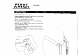
D) Measure the thickness of the door. Doors vary in thickness
depending on the manufacturer. Determine the distance to
the center of the edge of the door (half the thickness of the
door). Using the awl (or nail), mark a point on the edge of the
door where the centerline pencil mark (from Step 1C) and the
center of the edge of the door meet (half the thickness). See
Figure #3.
Step 2
Drill the Door
A) Usingthe2-1/8″holesaw,drillthecrossboreholecentered
on the mark made on the face of the door from Step 1B. See
Figure #3. Important: To avoid splintering or marring the
door,drillfromonesideofthedooruntilthepilotbitcomes
through the door. Then drill from the other side of the door,
usingtheholemadebythepilotbitasyourguideuntilthe
crossboreholeiscomplete.
B) Usingthe1”bit,drilltheedgeboreholecenteredonthemark
made on the edge of the door where the centerline and center
thickness met from Step 1D, see Figure #3. Important:
Makesurethatyoudrillafull3-1/2″deeptoaccommodate
theoveralllengthofthe2-3/8″latch.Ifyouareusinga2-3/4″
backsetlatch,thentheoveralldepthmustbeatleast3-3/4″.
3-1/2″
2-3/8″
2-3/4″
3-3/4″
For 2-3/8″ Backset
For 2-3/4″ Backset
Cross Bore
Hole - 2-1/8″
Diameter
Mark from
Step 1B
Edge Bore
Hole - 1″
Diameter
Mark from
Step 1D
Door Thickness
Faceplate
Mortise
Area
Centerline
Mark from
Step 1C
Minimum
5-1/2
to center
line of door-
knob cross
bore hole
Door Hardware
Installation Instructions
Single Cylinder Deadbolt
NOTE: Deadbolts t doors 1-3/4” to 2-1/4” thick.
For thicker doors, please call customer service.
Carefully unpackage all components and place them within easy
reach. Find Figure #1 on Page 5 of these instructions for a listing
and drawing of each component. Detach Figure #1 and place
besidethecomponentsforeasyreference.Checkyourdoorto
seeifithasbeenprepped(pre-drilled)forinstallingadeadbolt.
Ifyourdoorhasbeenpreppedforinstallation,startatStep4.If
yourdoorhasnotbeenpreppedforinstallation,youwillneeda
#2Phillipsscrewdriver,adrill,a2-1/8″holesaw,adrill,a7/64″
drillbit,a1″drillbit,achisel,apencil,tapeandanawl(ornail).
Step 1
Mark the Door
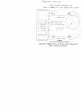
A) Locate the Door Preparation Template which is included
with these instructions. Fold the template along the “edge-
of-door” line. Important: Before positioning the template,
make sure that you are aligning it on the non-hinged edge of
the door. Carefully position the template so that the narrow
portion of the template wraps around the edge of the door,
and the large portion of the template remains on the face
of the door, see Figure #2. Slide the template up or down
on your door so that the horizontal centerline is located at
aheightthatisattractiveinappearanceandatleast5-1/2″
abovethecenterofthedoorknobhole.Onceyouhavechosen
the height, tape the template to the door.
B) Thebacksetisthedistacefromtheedgeofthedoortothe
centerofthecrossborehole.Standardbacksetsare2-3/8″
and2-3/4″.Determinethebacksetofthedeadboltlatch(Part
#1)bycheckingthemarkingonthelatchitself.Ifthelatch
isnotmarked,measurethelatchbetweenpointsAandB
todeterminethebackset,asshowninFigure #2.Onceyou
knowyourbackset,ndthepointonthetemplatewhere
the centerline crosses the vertical line that corresponds with
thecorrectbackset.Usingtheawl(ornail)markthispoint,
making sure that it is marked well enough to see on the door
once the template is removed.
C) Follow the centerline around the edge of the door and using
a pencil, extend the centerline onto the edge of the door. The
markshouldbeparalleltotheoor.Oncethismarkismade,
you may remove the template from the door.
Page1-PK147
For
Assistance
Call:
1-800-522-7336
8 am - 5 pm, Monday - Friday, MST
(A)
(B)
Template
Edge
of
Door
Face of Door
Centerline
Latch
Backset
Measurement
2-3/8” or 2-3/4”
Figure #2
Figure #3
C) Installthe3/4”latch&strikewoodscrews(Part#3)tohold
thedeadboltlatchanddeadboltfaceplateinplace.
Step 5
Install the “Outside” Half of the Deadbolt
A) Using Figure #1 for reference, gather together the cylinder
assembly(Part#4),spinring(Part#5A),theoutside
escutcheon(Part#5B),thedeadboltadaptorplate(Part#7)
andtwo1-1/4″machinescrews(Part#8).
B) Placethespinringoverthecylinderdriverbar(Part#4A)
end of the cylinder, making sure that the narrower edge of
the spin ring is closest to the key hole end of the cylinder.
Insertthecylinderthroughthespinringandescutcheonto
maketheoutsideassemblycomplete,seeFigure #5.
C) Fromtheoutsideofthedoor,insertthecylinderdriverbar
(Part#4A)throughthe“+”inthelatchhousing,making sure
that the driver bar is oriented vertically with the latch bolt
extending from the edge of the door.
D) Makesurethatthecrossboreholewillbecompletelycovered
bytheoutsideescutcheonandthattheGrandeurlogois
oriented correctly.
E) Ontheinsideofthedoor,placetheadaptorplatesothatthe
beveledscrewholesfaceawayfromthedoorandlineupwith
thecylinderposts.Screwonthetwo1-1/4″machinescrews
toholdtheoutsideassemblyinplace,seeFigure #6. Do not
tighten yet.
F) Align the outside escutcheon and cylinder with the door
edgeandsnugthetwo1-1/4″machinescrewsdown.Donot
overtighten.
G) Usingthekey,unlockandre-lockthelatchtomakesurethat
theactionissmooth.Ifthescrewshavebeenovertightened,
thelatchmaybind.Oncetheactionisacceptable,moveonto
Step6.
Step 3
Mortise for the Faceplate
A) Using Figure #1forreference,ndthefaceplate(Part#2).
Ontheedgeofthedoor,centerthefaceplateoverthenewly
drillededgeborehole,sothattheD-shapedholeinthe
faceplateiscenteredoverthe1″edgeborehole.Alignthe
faceplate so that the edges are parallel to the edges of the door
and roughly centered side-to-side. Mark around the faceplate
with a pencil and remove from door.
B) Using the chisel, score the outline of the faceplate. Next,
chiselawaythematerialwithintheoutlinetoadepthof1/8″.
Whenyouaredone,youshouldbeabletoinsertthelatch
(Part#1)intotheedgeborehole,placethefaceplateoverthe
latchtongue(Part#1a),andhavethefaceplatebeushwith
the edge of the door.
C) Again, using the faceplate as a template and the awl as a
marking tool, mark for the two screw holes that will hold the
faceplate on the door. Remove the faceplate from the door
toavoidmarringthenish.Then,drillthetwoscrewholes
usinga7/64″drillbit.Makesuretheholesaredrilledatleast
1″deep.Havingtoosmallortooshallowaholecancausethe
screws to shear off.
Installing Your Lock
Step 4
Install the Latch
A) InsertascrewdriverintothelatchhousingandextendtheA)
Insertascrewdriverintothedeadboltlatchhousing(Part#1)
andextendthedeadbolt.Insertthedeadboltlatchintothe
edgeborehole,makingsurethatthe“+”isorientedtowards
theloweredgeorbottomsideofthedeadboltlatch,see
Figure #4.
B) Addthedeadboltfaceplateoverthedeadboltlatchandmake
surethatitcansitushinthemortisedoutarea.Note:Some
doors come prepared with rounded corners in the mortised-
outarea.Ifyourdoorispreparedlikethis,simplyuseachisel
tosquareoffthecornerssothatthefaceplateliesushwith
the edge of the door.
Page2-PK147
Figure #4
Figure #5
hv/RIENTEDONTHE
LOWEREDGE
$EADBOLT,ATCH
0ART
%XTENDED
$EADBOLT
0ART!
$EADBOLT
&ACEPLATE
0ART
v,ATCH3TRIKE
7OOD3CREWS
0ART
%DGE"ORE
(OLE
Step 7
Installing the Door Reinforcer and Strike
Note: If door jamb is already drilled, go to Step 7E below.
A) Withthedeadboltintheunlockedposition,closethedoor.
Fromtheinsideofthehouse,turnthethumbturnand
identifywheretheboltiscontactingthedoorjamb.Lightly
markthiswithapencilonthedoorjamb.Measuringin
from the door stop trim, identify the center mark where the
boltholeneedstobedrilled.Hint:Ifyoucannotseethe
boltclearly,orcannotmarkthejambwithapencilbecause
thedoorisclosed,youcancovertheendoftheboltwitha
lightamountoflipstickorsimilarlyvisiblematerial.When
youturnthethumbturn,thelipstickwillmarkthedoor
jamb.
B) Usinga7/8″drillbit,drilltwoholescentered5/16″above
andbelowthecentermark.Theseholeswilloverlap.Make
sureeachoneisatleast1-1/8″deep.
C) Cleanoutthehole(ifneeded)andinserttheblackdustbox
(Part #11). Close the door carefully, making sure not to
crushthedustbox.Makesurethatthedeadboltanddust
boxlineup.Ifnot,carefullyenlargetheholeasneeded.
D) Usingthestrikeplate(Part#14),marktheareatobe
mortisedoutforthedustbox(Part#11),doorframe
reinforcer (Part #12), and strike plate. Use a chisel to
mortisethisareaandmakesurethatonceassembled,the
strikeplatesitsushtothedoorjamb.
E) Placethedoorframereinforceroverthedustbox.Using
thedoorframereinforcerasaguide,ndtheholesclosest
totheoutsideofthehouseanddrilltwo7/64″x3″deep
holes for the reinforcer screws.
Step 6
Adding the Inside Thumbturn Assembly
A) Using Figure #1forreference,gathertogetherthethumbturn
assembly(Part#9),andthetwo5/8″thumbturnmachine
screws (Part #10).
B) Installthethumbturnassemblysuchthatthedriverbar
coming through the latch housing is inserted into the slot on
thebackofthethumbturn.
C) Aligntheholesonthethumbturnassemblywiththetwo
small holes on the adaptor plate.
D) Installthetwo5/8″thumbturnmachinescrews,makingsure
thattheplateispositionedcorrectlybeforetighteningthe
screws. Do not over-tighten the screws.
E)Turnthethumbturnandthekeyseparatelytomakesurethat
theactionissmooth.Ifthescrewshavebeenover-tightened,
thelatchmaybind.Oncetheactionisacceptable,moveonto
Step7.
Page3-PK147
Figure #6
Figure #7
Figure #8
$OOR&RAME
2EINFORCER
0ART
3TRIKE0LATE
0ART
v7OOD
3CREWS
0ART
v,ATCH
3TRIKE7OOD3CREW0ART
$OOR
3TOP
4RIM
$UST"OX
0ART
F) Installthereinforcerscrews.Again,checktomakesurethe
deadboltandreinforcerlineupandthatthedeaboltcanbe
locked.
G) Drilltwoholesforthestrikeplateandinstallthestrikeplate
using the latch and strike wood screws (Part #3).
Congratulations! You are now
on your way to enriching your
life with !
Page4-PK147
Figure #1
Page5-PK147
Exterior
Cylinder
Assembly
(Part #4)
Cylinder Bar
(Part #4A)
Spin Ring
(Part #5A)
Deadbolt
Escutcheon
(Part #5B)
Security Ring
(Part #16)
Deadbolt Latch
(Part #1)
Deadbolt
(Part #1A)
Deadbolt
Adapter Plate
(Part #6)
Deadbolt
Faceplate
(Part #2)
Thumbturn
Assembly
(Part #8)
5/8” Thumbturn
Machine Screws
(Part #9)
3/4” Latch &
Strike Wood
Screws
(Part # 3)
1-1/4”
Machine
Screws
(Part #7)
Strike Plate
(Part #13)
3“ Wood Screws
(Part #12)
Door Frame
Reinforcer
(Part #11)
Dust Box
(Part #10)
  • Page 1 1
  • Page 2 2
  • Page 3 3
  • Page 4 4
  • Page 5 5

Grandeur GEOEDN-68-SN-KD Operating instructions

Type
Operating instructions

Ask a question and I''ll find the answer in the document

Finding information in a document is now easier with AI