INSTALLATION INSTRUCTIONS
Item#845-84/108-L (New. 10/17/2018)
READ AND SAVE THESE INSTRUCTIONS
WARNING! SHUT POWER OFF AT FUSE OR CIRCUIT BREAKER.
AVERTISSEMENT! COUPER LE COURANT AU NIVEAU DES FUSIBLES OU DU DISJONCTEUR.
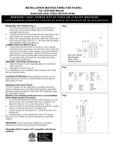
Fig. 2
Fig. 3
Fig.1
HANGING THE FIXTURE (Fig. 1)
1. Carefully remove the fixture from the carton and check that all
parts are included as shown in the illustration.
2. Shut off power at the circuit breaker and remove the old fixture
including the mounting hardware.
3.
Position the mounting plate (C) on the ceiling and mark the
location of the three drywall anchors (A). Pre-drill the holes for
the drywall anchors (A). Then insert the drywall anchors (A) into
the ceiling.
4. Thread mounting screws (B) into the pre-dri
lled holes in
mounting plate (C). Spaced the same distance apart as the
holes in the ceiling pan (I) and secure with hex nut (D).
5. Attach mounting plate (C) to the outlet box using mounting
screws (F) (Size: #8-32N*L0.5”) and wood screws (E
drywall anchors (A). The side of the mounting plate marked
“GND” must face out.
CONNECTING THE WIRES (Fig. 2)
6. At this point, c
onnect the electrical wires as shown in Fig. 2,
making sure that all wire connectors are secured. If your outlet
box has a ground wire (gree
n or bare copper), connect the
fixture’s ground w
ire to it. Otherwise, connect the fixture’s
ground wire directly to the mounting plate using the green screw
provided. After wires are connected, tuck them carefully inside
the junction box.
COMPLETING THE INSTALLATION (Fig. 1)
7.
Place the ceiling pan (I) onto the mounting screws (B) and
secure with the cap nuts (H).
8. Through the nipple (K) (with the nut side) onto the metal washer
(P), plastic washer (O) and glass shade (Q), then secure them
on the coupling (G). (Notice: Please don't secure
prevent the glass from breaking)
9. Through glass shield (L), into the nipple (K) and secure by using
the finial (M).
Your installation is now complete. Return power to the junction box
and test the fixture.
CAUTION/ATTENTION:
When handling the fixture, do not apply
pressure to the LEDs. Hold the fixture by the base or ceiling pan (I)
only.
Replacing LED module (Fig.3)
The LED module can be replaced by a qualified electrician without
cutting the wires and without damaging the decorative element to
which the fixture is attached. See installation steps for more details
(Fig.3)
Warning: Turn off power at the fuse box or circuit breaker
before replacing the LED module.
a. Loosen finial (M) and remove glass shade (L).
b. To remove the fixture from the ceiling: loosen the cap nuts (H)
and remove the wire connectors. Then place the fixture on a
clear flat surface (Fig.3).
c. Loosen nipple (K) and remove the metal washer (P), plastic
washer (O) and glass shade (Q).
d. Loosen screws (T), then carefully remove the LED module (N)
from ceiling pan (I).
e. Use a pin to press from the hole of the quick connector and
disconnect the black/white wire respectively.
f. Reverse steps a-e for installing the new LED module.
Note: The LED module should be pr
supplier.
IMPORTANT: Fixture should be installed by a qualified
electrician to ensure proper wiring and installation.
Dimmable with ELV and/or LED compatible wall
dimmer switches.
WIRES
Black or
WIRES
Black
(Hot)
WIRES
White or
WIRES
White
(Neutral)
WIRES
Bare
Copper
(Ground)
WIRES
Green
(Ground)
A-020-378
Mounting Plate
Ground Screw
Mounting Screw*2