
P/N: 1802040000002
*1802040000002*
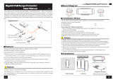
MDS-G4000 Series
Quick Installation Guide
Version 1.1, April 2020
Technical Support Contact Information
www.moxa.com/support
Moxa Americas:
Toll
-free: 1-888-669-2872
Tel:
1-714-528-6777
Fax:
1-714-528-6778
Moxa China (Shanghai office):
Toll
-free: 800-820-5036
Tel:
+86-21-5258-9955
Fax:
+86-21-5258-5505
Moxa Europe:
Tel:
+49-89-3 70 03 99-0
Fax:
+49-89-3 70 03 99-99
Moxa Asia-Pacific:
Tel:
+886-2-8919-1230
Fax:
+886-2-8919-1231
Moxa India:
Tel:
+91-80-4172-9088
Fax:
+91-80-4132-1045
2020 Moxa Inc. All rights reserved.

- 2 -
Package Checklist
Moxa’s MDS-G4000 Series industrial modular DIN-rail switch is shipped
with the following items. If any of these items are missing or damaged,
please contact your customer service representative for assistance.
• 1 MDS-G4000 switch
• RJ45 to RS-232 9 pin female console cable
• 2 protective caps for unused ports
• Pre-installed DIN-rail kit (MDS-G4012 x 1, MDS-G4020/28 x 2)
• Quick installation guide (printed)
• Substance Disclosure Table
• Product Certificate of Quality Inspection (Simplified Chinese)
• Product Notices (Simplified Chinese)
• Warranty card
NOTE
You can find information and software downloads on the
relevant p
roduct pages located on Moxa’s website:
www.moxa.com
Default Settings
• IP address: 192.168.127.253
• Subnet Mask: 255.255.255.0
• Username: admin
• Password: moxa
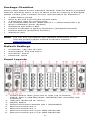
Panel Layouts
1. System status LEDs (from left to right, top to bottom)
STATE, FAULT, MASTER/HEAD, COUPLER/TAIL and SYNC LED
indicators
2. USB port (Reserved for future)
3. Module Status
4. Switch and Control Module slot 1 (Embedded)
5. Ethernet module slot 2
6. Ethernet module slot 3
7. Ethernet module slot 4 (For MDS-G4020/28)
8. Ethernet module slot 5 (For MDS-G4020/28)

- 3 -
9. External power input status from EPS
10. Ethernet module slot 6 (For MDS-G4028)
11. Ethernet module slot 7 (For MDS-G4028)
12. External Power Supply input for PoE
13. Redundant power module slot 1
14. Redundant power module slot 2
15. RS232 console port with RJ45 interface
16. Reset button (Pin hole 0.9 mm)
17. Relay output and Digital Input port
18. Relay output
19. Power input
20. Grounding screw
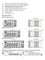
Dimensions
MDS-G4012 Series
MDS-G4020 Series
MDS-G4028 Series
Unit: mm (inch)
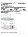
Ethernet Modules (Hardware Rev.2.0.0 and above)
LM-7000H-4GTX
LM-7000H-4GSFP

- 4 -
LM-7000H-4GPoE
LM-7000H-4TX
LM-7000H-4PoE
Power Modules (Hardware Rev.2.1.0 and above)
PWR-HV-P48
PWR-LV-P48
DIN-Rail Dimension and Instructions
MDS-G4012 Series
MDS-G4020/MDS-G4028 Series
1. Insert the upper lip of the DIN-rail into the DIN-rail mounting kit.
2. Press the device towards the DIN-rail until it snaps into place.
3. Pull down the two latches one by one to release the DIN-rail kit and
lift up to remove the device from the DIN-rail.
NOTE
The
DIN-rail must use TS35 (15 mm) specification for the MDS-
G4000 Series.

- 5 -
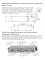
Wall Mount Dimension and Instructions (Optional:
WK-112-01)
Mounting the switch to a wall requires four screws. The
heads of the screws should be between 6.0 to
9.0 mm
in diameter, and the diameter of screw thread should
be between 3.5 to 4 mm, as shown in the figure shown
on the right
. Use the MDS-G4000 Series with the wall
mounting kit attached, as a guide to mark the correct
locations of the eight screws.
Rack Mounting Dimension and Instructions
(Optional: RK-3U-01)
The rack mount kit is designed for two MDS-G4028 products. To mount
the rack mount kit, please assemble the right and left part of the kit
(indicated with No. 1 below) with four screws. Then assemble the part
of the rack kit (indicated with No. 2 below) with eight screws in order to
combine the two MDS-G4028 products.

- 6 -
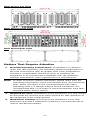
Rack Mount Top View
Rack Mount Front View
Rack Mount Rear View
Matters That Require Attention
1. Elevated Operating Temperature: If installed in a closed or
multi-unit rack assembly, the operating ambient temperature of
the rack environment may be greater than room temperature.
Therefore, consideration should be given to installing the
equipment in an environment compatible with the maximum
ambient temperature (Tma) specified by the manufacturer.
NOTE
In order to ensure reliable operations, please make sure the
operating temp
erature
of the environment does not exceed the
spec. When mounting a rack
-mounted switch with other
operating units in a cabinet without forced ventilation, it is
recommended that 1U of space is reserved between each rack
-
mounted switch and/or device.
2. Required Air Flow: Installation of the equipment in a rack should
be such that the amount of air flow required for safe operation of
the equipment is not compromised.
3. Mechanical Loading: Mounting of the equipment in the rack
should be such that a hazardous condition is not achieved due to
uneven mechanical loading.

- 7 -
4. Circuit Overloading: Consideration should be given to the
connection of the equipment to the supply circuit and the effect
that overloading of the circuits might have on overcurrent
protection and supply wiring. Appropriate consideration of
equipment nameplate ratings should be used when addressing this
concern.
5. Reliable Grounding: Reliable grounding of rack-mounted
equipment should be maintained. Particular attention should be
given to supply connections other than direct connections to the
branch circuit (e.g. use of power strips).
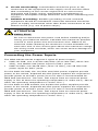
ATTENTION
Safety First
!
Be sure to disconnect the power cord before installing and/or
wiring your Ethernet Switch.
Calculate the maximum possible
current in each power wire and common wire. Observe all
electrical codes dictating the maximum current allowable for
each wire size. If the current goes above the maximum ratings,
the wiring could overheat,
which can cause serious damage to
your equipment.
Connecting the Power Inputs
The MDS-G4000 Series supports 2 types of power supply:
• PWR-HV-P48: one 110/220 VAC/VDC (90 to 264 VAC, 88 to 300
VDC), one 48VDC PoE power input for PoE+ ports.
• PWR-LV-P48: one 24/48 VDC (18 to 72 VDC), one 48 VDC PoE
power input for PoE+ ports.
For the PWR-HV-P48, the 110/220 VAC/VDC power supplies provide
power to the switch. Separate 48 VDC power supplies are required to
provide power to all PoE+ ports (50 to 57 VDC is recommended for
IEEE 802.3at devices. The max. PoE output from an external power
supply is 720 W when the operating temperature is under 60°C; 360 W
when the operating temperature is under 75°C.)
For the PWR-LV-P48 models, the 24/48 VDC power supplies provide
power to the switch. Separate 48 VDC power supplies are required to
provide power to all PoE+ ports (50 to 57 VDC is recommended for
IEEE 802.3at devices. The max. PoE output from an external power
supply is 720 W when the operating temperature is under 60°C; 360 W
when the operating temperature is under 75°C.)

- 8 -
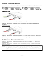
Power Terminal Blocks
The connection for power input and PoE external power supply is on the
power modules.
PWR-HV-P48
STEP 1: Insert the neutral/line (L/N/Ground) AC wires into the
terminals.
STEP 2: Insert the terminal block connector into the terminal block
receptor.
PWR-LV-P48
STEP 1: Insert the negative/positive (-/+) DC wires into the terminals.
STEP 2: Insert the terminal block connector prongs into the terminal
block receptor.
PoE Power Terminal Blocks
STEP 1: Insert the negative/positive DC wires into the -/+ terminals,
respectively.
STEP 2: Insert the terminal block connector prongs into the terminal
block receptor.
NOTE
In order to have higher levels of protection against surge, it is
suggested
to install a surge protector in front of the power
input
of the PoE powered device so that it is suitable for use in
IEC 61850 conditions.

- 9 -
NOTE
When wiring the power input, we suggest using the cable type -
AWG (American Wire Gauge) 18 (1.03
mm
2
) and the
corresponding pin type cable terminals. The connector must be
able to withstand torque at maximum 5 pound
-inches. The
rated temperature of wiring should be at least 105°C.
NOTE
When two power units are installed on the MDS
-G4000 Series
switch, both power units will be activated simultaneously, which
will enable power redundancy.
NOTE
The reverse power input connection will not activate the device
or PoE input
. In addition, the PoE will only activate when the
external power supply is installed on the same power unit.
Wiring the Relay Contact
Each power module has one relay output that can provide two types of
relay output. Refer to the table below for detailed information.
The relay contact is used to detect user-configured events. Two wires
are attached to the relay pins with normally close and normally open
options.
FAULT:
The relay contact of the 3-pin terminal block connector is used to detect
user-configured events. The module provides normally open and
normally closed circuits depending on what the user chooses. For pin
definitions refer to the table below.
Relay Connection
Power Off
Boot up Ready
Event Trigger
NO and COM
Closed Circuit
Open Circuit
Closed Circuit
NC and COM
Open Circuit
Closed Circuit
Open Circuit
NOTE
When wiring the relay contact, we suggest using the cable type
-
AWG (American Wire Gauge) 16-24 (1.31-0.205 mm
2
) and
the corresponding pin type cable terminals. The connector must
be able to withstan
d torque at maximum 5 pound-inches. The
rated temperature of wiring should be at least 105°C.
Digital Input/Output
Digital Output
1 relay output with current carrying capacity of 2 A @ 30 VDC
Digital Input
1 digital output with the same ground, but electrically isolated from the
electronics
• +13 to +30 V for state 1
• -30 to +1 V for state 0
• Max. input current: 8 mA

- 10 -
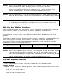
Install/Remove the Ethernet module
The Ethernet modules are hot-swappable for the same module type.
You have the option to mount or remove the Ethernet module while the
device is operating.
NOTE
1. When performing a cold start, you cannot remove and
insert a module before booting up as it will cause the
module to initially fail.
2.
The default module is 4GTX, if it is the first time to mount
4TX, PoE, or SFP module, please reboot the switch after
inserting it. The hot-swappable function, as defined above,
will work after the device is rebooted for the first time.
3.
If a different model type module is changed on the same
slot, it is recommend to reconfigure the settings or reset
the device to default settings after rebooting the switch.
The installation procedure is as follows:
1. Insert the Ethernet module straight into the slot
2. Fasten the module to the device by tightening the 2 screws. The
tightening torque is 3.5 kgf-cm (0.35 Nm)
The removal procedure is as follows:
1. Loosen the 2 screws of the module
2. Pull the module out of the slot
3. Insert the dummy module in to the slot in order to have better
protection against dust and EMI
4. Fasten the dummy module using 2 screws. The tightening torque is
4 kgf-cm (0.4 Nm)
Install/Remove the Power module
The power supply units are hot-swappable when both power modules
are installed. You have the option to mount or remove the power
supply units while the device is operating.
The installation procedure is as follows:
1. Insert the power unit straight into the slot
2. Fasten the unit to the device by tightening the 2 screws. The
tightening torque is 3.5 kgf-cm (0.35 Nm)
The removal procedure is as follows:
1. Loosen the 2 screws of the module
2. Pull the module out of the slot
3. Insert the dummy module in to the slot in order to have better
protection against dust and EMI.
4. Fasten the dummy module using 2 screws. The tightening torque is
4 kgf-cm (0.4 Nm)
NOTE
If one of the modules is removed from the device, it is
advisable to insert a dummy module in order to provide better
protection against dust and EMI.

- 11 -
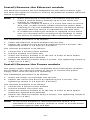
Grounding the Moxa Industrial DIN-rail Switch
Grounding and wire routing help limit the effects of noise due to
electromagnetic interference (EMI). Run the ground connection from
the ground screw to the grounding surface prior to connecting devices.
NOTE
Using a shielded cable achieves better electromagnetic
resistance.
RS-232 with RJ45 Interface Console Connection
The switch has an RS-232 serial console with an RJ45 interface. Please
use a Moxa 9-pin female console cable to connect to your PC's COM
port (or via USB-to-Serial converters or hubs). You can then use a
console terminal program, such as Moxa’s PComm Terminal Emulator,
to access the console configuration utility of the switch.
RS-232 Setup:
• Baud rate: 115,200
• Data Bits: 8
• Parity: None
• Stop Bits: 1
• Terminal Type: VT100
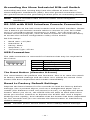
USB Connection
The USB connection is reserved for functions that may be required in
the future.
Pin
Description
1
VCC (+5V)
2
D- (Data-)
3
D+ (Data+)
4
GND (Ground)
The Reset Button (diameter 0.9 mm)
The reset button can perform two functions. One is to reset the switch
to factory default settings and the other is to reboot the switch if the
button has been depressed and release immediately.
Reset to Factory Default Settings
Depress the Reset button for five seconds to load the factory default
settings. Use a pointed object, such as a straightened paper clip or
needle (the diameter must not exceed 0.9 mm), to depress the Reset
button. When you do so, the STATE LED will start to blink about four
times per second. Continue to depress the STATE LED until it begins
blinking more rapidly; this indicates that the button has been depressed
for five seconds and you can release the Reset button to load factory
default settings.
NOTE
DO NOT power off the switch when loading default settings.

- 12 -
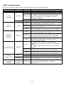
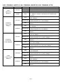
LED Indicators
The function of each LED is described in the table below.
LED
Color
State
Description
System LEDs
STA
(STATE)
Green
On
Normal operation
Blinking
1. The system is booting up
2. When pressing the reset button
and continue 5 seconds to reset
factory default
Off
N/A
Red
On
The system has initially failed
FLT
(FAULT)
Red
On
1. Switch initial failure
2. EEPROM information error
Blinking
When switch boot up and firmware
load to memory
Off
When system boot up and run well or
user-configured event is not trigger
M/H
(MSTR/
HEAD)
Green
On
When the switch is Master/Head/Root
of Turbo Ring/Turbo Chain
Blinking
When the switch is Ring Master/Head
of Turbo Ring/Turbo Chain and the
Turbo Ring/Turbo Chain is broken
Off
When the switch is not the
Master/Head/Root of this Turbo
Ring/Turbo Chain
C/T
(CPRL/TAIL)
Green
On
1. When the switch enables the
coupling function to form a back-up
path
2. When the switch is tail of Turbo
Chain
Blinking
When the switch is enable Turbo
Chain and Turbo Chain is broken
Off
When the switch disables the
coupling or tail role of Turbo Chain.
SYNC
(Reserved)
Amber
On
PTP function is enabled
Blinking
The switch receives sync packets
Green On
The PTP function is successful
converged
System LED
(Except
PWR)
Green/
Amber/
Red
Blinking
The switch is being
discovered/located by locator
function

- 13 -
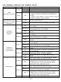
LM-7000H-4GTX/LM-7000H-4GSFP/LM-7000H-4TX
LED
Color
State
Description
MS
(Module
State)
Green
On
Normal operation
Blinking
This module is booting up
Off
The module is out of service
Red On
1. The module has initially failed
2. When insert module by different
model
Copper
(10/100
Mbps)
Green
On
When the port is active and links on
100 Mbps.
Blinking
When the port’s data is being
transmitted at 100 Mbps.
Off
When the port is inactive or link
down.
Amber
On
When the port is active and links on
10 Mbps.
Blinking
When the port’s data is being
transmitted at 10 Mbps.
Off
When the port is inactive or link
down.
Copper
(10/100/
1000Mbps)
Green
On
When the port is active and links on
1,000 Mbps.
Blinking
When the port’s data is being
transmitted at 1,000 Mbps.
Off
When the port is inactive or link
down.
Amber
On
When the port is active and links on
10/100 Mbps.
Blinking
When the port’s data is being
transmitted at 10/100 Mbps.
Off
When the port is inactive or link
down.
SFP
(100/1000
Mbps)
GREEN
ON
When the port is active and links on
1,000Mbps.
Blinking
When the port’s data is being
transmitted at 1,000 Mbps.
OFF
When the port is inactive or link
down.
Amber
On
When the port is active and links on
100 Mbps.
Blinking
When the port’s data is being
transmitted at 100 Mbps.
Off
When the port is inactive or link
down.

- 14 -
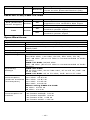
LM-7000H-4GPoE/LM-7000H-4PoE
LED
Color
State
Description
MS
(Module State)
Green
On
Normal operation
Blinking
The module is booting up
Off
This module is out of service.
Red On
1. The module has initially failed
2. When insert module by different
model
3.
When cold start, remove and insert
module before initial done
EPS
(External Power
Supply for PoE
module)
Amber
On Normal operation
Off No external power supply for PoE.
Copper
(10/100
Mbps)
Green
On
When the port is active and links on
100 Mbps.
Blinking
When the port’s data is being
transmitted at 100 Mbps.
Off
When the port is inactive or link
down.
Amber
On
When the port is active and links on
10 Mbps.
Blinking
When the port’s data is being
transmitted at 10 Mbps.
Off
When the port is inactive or link
down.
Copper
(10/100/
1000Mbps)
Green
On
When the port is active and links on
1,000Mbps.
Blinking
When the port’s data is being
transmitted at 1,000 Mbps.
Off
When the port is inactive or link
down.
Amber
On
When the port is active and links on
10/100Mbps.
Blinking
When the port’s data is being
transmitted at 10/100 Mbps.
Off
When the port is inactive or link
down.
PoE/PoE+
Green
On
When the port is connected to IEEE
802.3at powered device (PD)
Off
1. When the power is not being
supplied to a powered device (PD)
2. The port is not connected to an
IEEE 802.3at standard PD
Amber
On
When the port is connected to IEEE
802.3af powered device (PD)
Blinking
The PoE power has been shut off
because low power budget
Off
1. When the power is not being
supplied to a powered device (PD)
2. The port is not connected to an
IEEE 802.3af standard PD
Red
On
Powered device (PD) detection failure

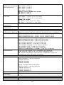
- 15 -
LED
Color
State
Description
Blinking
When detecting over current or short
circuit on the powered Device (PD)
Off
PoE is normal operation
PWR-HV-P48/PWR-LV-P48
LED
Color
State
Description
EPS (External
Power Supply)
Amber
On
External Power Supply is being
supplied to the module's EPS input
Off
No external power supply for PoE
PWR Amber
On
Power is being supplied to the
module's power input
Off
Power is not being supplied to the
module's power input
Specifications
Interface
Gigabit Ethernet
4-ports 10/100/1000BaseT(X)
Console Port
RS-232 console with an RJ45 interface
LED Indicators
PWR, EPS, STATE, SYNC, FAULT, MSTR/HEAD,
CPLR/TAIL
Relay Output
2 A @ 30 VDC
Power Requirements
Input Voltage
PWR-HV-P48:
110/220 VDC, 110 VAC, 60 Hz, 220 VAC, 50 Hz,
PoE: 48 VDC (53 to 57 VDC is
recommended of PoE+
device)
PWR-LV-P48: 24/48 VDC
PoE: 48 VDC (53 to 57 VDC is recommended of PoE+
device)
Operating
Voltage
PWR-HV-P48:
88 to 300 VDC, 90 to 264 VAC, 47 to 63 Hz, PoE: 46
to 57 VDC
PWR-LV-P48: 18 to 72 VDC, PoE: 46 to 57 VDC
Power
Consumption
(without modules
consumption)
When using PWR-HV-P48:
110 VDC: 12.43 W
220 VDC: 12.87 W
110 VAC: 13.42 W
220 VAC: 14.08 W
When using PWR-LV-P48:
24 VDC: 12.67 W
48 VDC: 13.2 W
Power
Consumption of
module
LM-7000H-4GTX: 3.63 W
LM-7000H-4GPoE: 3.8 W
LM-7000H-4GSFP: 4.8 W
LM-7000H-4TX: 1.85 W
LM-7000H-4PoE: 1.85 W

- 16 -
Input Current
(without modules
consumption)
When using PWR-HV-P48:
110 VDC: 0.11 A
220 VDC: 0.06 A
110 VAC: 0.29 A
220 VAC: 0.18 A
When using PWR-LV-P48:
24 VDC: 0.53 A
48 VDC: 0.28 A
Peak Inrush
Current
PWR-HV-P48:
110 VAC: <10 A (t > 0.1 ms)
220 VAC: <20 A (t > 0.1 ms)
PWR-LV-P48:
24 VDC: <5 A (t > 0.1 ms)
48 VDC: <10 A (t > 0.1 ms)
Overload Current
Protection
Present
Reverse Polarity
Protection
Present
Physical Characteristics
Ingress
Protection Rating
IP40 (This rating will only be achieved when the relay
output terminal block and all modules are installed.)
Dimensions
MDS-G4012 Series: 134 x 115 x 163.25 mm
MDS-G4020 Series: 176 x 115 x 163.25 mm
MDS-G4028 Series: 218 x 115 x 163.25 mm
Weight
MDS-G4012 Series: 2.00 kg (4.41 lb)
MDS-G4020 Series: 2.50 kg (5.51 lb)
MDS-G4028 Series: 2.84 kg (6.26 lb)
LM-7000H-4GSFP: 0.3 kg (0.66 lb)
LM-7000H-4GTX: 0.24 kg (0.53 lb)
LM-7000H-4GPoE: 0.31 kg (0.69 lb)
LM-7000H-4TX: 0.24 kg (0.53 lb)
LM-7000H-4PoE: 0.31 kg (0.69 lb)
PWR-HV-P48/PWR-LV-P48: 0.36 kg (0.69 lb)
Installation
Din-rail mounting: Pre-installed by default
Wall mount: WK-112-01 (with optional kit)
19'' rack mounting: RK-3U-01 (optional, only for
combining two 28-port models)
Environmental Limits
Operating Temp.
Standard Temperature Models:
-10 to 60°C (-14 to 140°F)
- MDS-G4012
- MDS-G4020
- MDS-G4028
Wide Temperature Models:
-40 to 75°C (-40 to 167°F)
- MDS-G4012-T
- MDS-G4020-T
- MDS-G4028-T
Storage Temp.
-40 to 85°C (-40 to 185°F)
Ambient Relative
Humidity
5 to 95% (non-condensing)
Standards and Certifications
Safety
EN 62368-1
EMC
EN 55035/55032

- 17 -
EMI
CISPR 32, FCC Part 15B Class A
EMS
IEC 61000-4-2 ESD: Contact: 8 kV; Air: 15 kV
IEC 61000-4-3 RS: 80MHz to 1GHz: 20 V/m
IEC 61000-4-4 EFT: Power: 4 kV; Signal: 4 kV
IEC 61000-4-5 Surge: Power 4 kV; Signal: 4 kV
IEC 61000-4-6 CS: 10V
IEC 61000-4-8 PFMF
IEC 61000-4-11 Voltage Dips & Interruptions
Note: For better conductive radiation immunity, it is recommended to
use a STP cable and install a surge protector at the PoE power input:
EPS.
Rail Traffic
EN 50121-4
Traffic Control
NEMA TS2
Shock
IEC 60068-2-27
Freefall
IEC 60068-2-31
Vibration
IEC 60068-2-6
Warranty
Warranty Period
5 years
Details
See www.moxa.com/warranty
Restricted Access Locations
• This equipment is intended to be used in Restricted
Access Locations, such as a computer room, with
access limited to service personnel or users who have
been instructed on how to handle the metal chassis of
equipment that is very hot. The location should only be accessible
with a key or through a security system.
• External metal parts of this equipment are extremely hot. Before
touching the equipment, you must take special precautions to
protect your hands and body from serious injury.
-
 1
1
-
 2
2
-
 3
3
-
 4
4
-
 5
5
-
 6
6
-
 7
7
-
 8
8
-
 9
9
-
 10
10
-
 11
11
-
 12
12
-
 13
13
-
 14
14
-
 15
15
-
 16
16
-
 17
17


Moxa MDS-G4028 Series Quick Installation Manual
- Type
- Quick Installation Manual
- This manual is also suitable for
Ask a question and I''ll find the answer in the document
Finding information in a document is now easier with AI
Related papers
-
Moxa MDS-G4028-L3 Series Quick setup guide
-
-
Moxa MDS-G4012 Series Installation guide
-
Moxa DR Power Supply Series Quick setup guide
-
-
 Moxa Technologies DR-120-24 Quick Install Guide
-
Moxa Technologies HDR-60-24 Series Quick Install Guide
-
-
-

Other documents
-
TELRAN 560925 User manual
-
RODE Microphones AI-1 Quick start guide
-
 UTEPO UTP3-VSP201GE-POE User manual
-
KTI Networks KSD-541 User manual
-
Wieland wienetUMS 8-4POE-W User manual
-
Elsema G4000 User guide
-
Hirschmann 943 880-001 Datasheet
-
Alcatel-Lucent OmniSwitch 6850-P48L Hardware User's Manual
-
Alcatel-Lucent OmniSwitch 6450-P48 User manual
-
Comelit HFX-7004M Technical Manual
