Page is loading ...

PW8
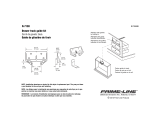
Pick-Up Header
Unloading and Assembly Instructions (North America)
215326 Revision A
Original Instruction
The Harvesting Specialists.

PW8 Pick-Up Header
1006866
Published May 2020
© 2020 MacDon Industries, Ltd.
The information in this publication is based on the information available and in effect at the time of printing. MacDon
Industries, Ltd. makes no representation or warranty of any kind, whether expressed or implied, with respect to the
information in this publication. MacDon Industries, Ltd. reserves the right to make changes at any time without notice.

Introduction
This manual contains the unloading, setup, and predelivery requirements for the MacDon PW8 Combine Pick-Up Header
for North America.
Carefully read all the material provided before attempting to unload, assemble, or use the machine.
The header can be configured for the following combines:
Combine Model
Case IH
50/60/7088, 51/61/7130, 51/61/7140, 70/8010, 71/81/9120, 72/82/9230, and 72/82/9240
John Deere
96/97/9860STS, 96/97/9870, S650/660/670/680/690, 9660WTS, and T670
New Holland
All CR/CX Series
Versatile
RT490
When setting up the machine or making adjustments, review and follow the recommended machine settings in all relevant
MacDon publications. Failure to do so may compromise machine function and machine life and may result in a hazardous
situation.
NOTE:
Keep your MacDon publications up-to-date. The most current version can be downloaded from our website
(www.macdon.com) or from our Dealer-only site (https://portal.macdon.com) (login required).
215326 i Revision A

Summary of Changes
At MacDon, we’re continuously making improvements, and occasionally these improvements affect product
documentation. The following list provides an account of major changes from the previous version of this document.
Section
Summary of Change Internal Use Only
6.7 Running up the Header, page 135 Added step to watch draper at v-guide.
Service
6.4.3 Greasing Points, page 132
Added caster wheel image. Tech. Pubs
1.4 Safety Sign Locations, page 5 Added safety decal MD #304865.
ECN 58722
215326 ii Revision A

215326 iii Revision A
Introduction ................................................................................................................................................i
Summary of Changes....................................................................................................................................ii
Chapter 1: Safety .................................................................... .................................................................... 1
1.1 Signal Words ......................................................................................................................................... 1
1.2 General Safety ....................................................................................................................................... 2
1.3 Safety Signs ........................................................................................................................................... 4
1.4 Safety Sign Locations............................................................................................................................... 5
Chapter 2: Shipping Data............................................. ............................................................................. 13
Chapter 3: Unloading the Header .......................................... .................................................................. 15
3.1 Unloading with a Forklift........................................................................................................................ 15
3.2 Lowering Header .................................................................................................................................. 17
3.3 Removing Shipping Stands ..................................................................................................................... 18
3.3.1 Opening Left Endshield ................................................................................................................. 20
3.3.2 Closing Left Endshield ................................................................................................................... 20
3.4 Attaching Fixed Wheels ......................................................................................................................... 22
3.5 Attaching Caster Wheels ........................................................................................................................ 23
3.6 Setting Fixed Wheels to Field/Working Position ......................................................................................... 25
3.7 Setting Caster Wheels to Field/Working Position ........................................................................................ 26
3.8 Extending Hold-Down to Field/Working Position ........................................................................................ 27
3.9 Adjusting Transport Lights...................................................................................................................... 28
3.10 Repositioning Driveline Storage Bracket.................................................................................................. 29
Chapter 4: Reconfiguring Headers ......................................... .................................................................. 31
4.1 Configuring Headers for John Deere......................................................................................................... 31
4.1.1 Moving Stripper Assemblies ........................................................................................................... 31
4.1.2 Removing Flighting Extensions ....................................................................................................... 34
4.1.3 Installing Auger Fingers ................................................................................................................. 35
4.2 Configuring Headers for Case IH .............................................................................................................. 37
4.2.1 Moving Stripper Assemblies ........................................................................................................... 37
4.3 Configuring Headers for New Holland CX .................................................................................................. 40
4.3.1 Moving Stripper Assemblies ........................................................................................................... 40
4.3.2 Removing Flighting Extensions ....................................................................................................... 43
4.3.3 Installing Auger Fingers ................................................................................................................. 43
4.4 Configuring Headers for New Holland CR .................................................................................................. 46
4.4.1 Moving Stripper Assemblies ........................................................................................................... 46
4.4.2 Installing Flighting Extensions......................................................................................................... 48
4.4.3 Removing Auger Fingers................................................................................................................ 50
4.5 Adjusting Stripper Plate Clearance ........................................................................................................... 52
TABLE OF CONTENTS

215326 iv Revision A
Chapter 5: Attaching Header to Combine ............................................................................................... 53
5.1 Attaching Header to Case IH Combine ...................................................................................................... 53
5.2 Attaching Header to John Deere 60, 70, S, or T Series Combine .................................................................... 56
5.3 Attaching Header to New Holland CR/CX Series Combine ............................................................................ 60
5.4 Attaching Header to Versatile Combine .................................................................................................... 64
5.5 Removing Deck Shipping Braces .............................................................................................................. 69
5.6 Installing Crop Deflectors ....................................................................................................................... 70
Chapter 6: Predelivery Inspection.......................................... .................................................................. 71
6.1 Auto Header Height Control ................................................................................................................... 71
6.1.1 Auto Header Height Control System Overview .................................................................................. 71
6.1.2 Auto Header Height Control Sensor Operation .................................................................................. 72
6.1.3 Height Sensor Output Voltage Range – Combine Requirements ........................................................... 72
Manually Checking Voltage Range ................................................................................................. 72
Adjusting Header Height Sensor Voltage Range – Left Side................................................................. 75
Adjusting Header Height Sensor Voltage Range – Right Side ............................................................... 75
6.1.4 Case IH 5130/6130/7130 and 5140/6140/7140 Midrange Combines ..................................................... 77
Setting up the Header on the Combine Display (Case IH 5130/6130/7130; 5140/6140/7140) ................... 77
Checking Voltage Range from Combine Cab (Case IH 5130/6130/7130; 5140/6140/7140) ....................... 78
Calibrating Auto Header Height Control (Case IH 5130/6130/7130; 5140/6140/7140)............................. 80
Setting Preset Cutting Height (Case IH 5130/6130/7130; 5140/6140/7140) ........................................... 81
6.1.5 Case IH 7010/8010, 7120/8120/9120, 7230/8230/9230, and 7240/8240/9240 Combines ......................... 83
Checking Voltage Range from Combine Cab (Case 8010).................................................................... 83
Checking Voltage Range from Combine Cab (Case IH 7010/8010; 7120/8120/9120; 7230/8230/9230;
7240/8240/9240) ............................................................................................................. 85
Calibrating Auto Header Height Control (Case IH 7010/8010; 7120/8120/9120; 7230/8230/9230;
7240/8240/9240) ............................................................................................................. 87
Calibrating Auto Header Height Control (Case IH Combines with Version 28.00 or Higher
Software)........................................................................................................................ 89
Setting Preset Cutting Height (Case 7010/8010, 7120/8120/9120, 7230/8230/9230,
7240/8240/9240) ............................................................................................................. 91
6.1.6 John Deere 60 Series Combines ...................................................................................................... 92
Checking Voltage Range from Combine Cab (John Deere 60 Series) ..................................................... 92
Calibrating Auto Header Height Control (John Deere 60 Series)........................................................... 93
Turning Off Accumulator (John Deere 60 Series) .............................................................................. 94
Setting Sensing Grain Header Height to 50 (John Deere 60 Series)....................................................... 95
Setting Sensitivity of Auto Header Height Control (John Deere 60 Series).............................................. 96
Adjusting Threshold for Drop Rate Valve (John Deere 60 Series) ......................................................... 96
6.1.7 John Deere 70 Series Combines ...................................................................................................... 97
Checking Voltage Range from Combine Cab (John Deere 70 Series) ..................................................... 97
Calibrating Feeder House Speed (John Deere 70 Series)..................................................................... 98
Calibrating Auto Header Height Control (John Deere 70 Series)........................................................... 98
Setting Sensitivity of Auto Header Height Control (John Deere 70 Series).............................................. 99
Adjusting Manual Header Raise/Lower Rate (John Deere 70 Series) ................................................... 100
6.1.8 John Deere S and T Series Combines ............................................................................................. 100
Checking Voltage Range from Combine Cab (John Deere S and T Series)............................................. 100
Calibrating Feeder House Fore-Aft Tilt Range (John Deere S and T Series) ........................................... 101
Calibrating Auto Header Height Control (John Deere S and T Series) .................................................. 104
Setting Sensitivity of Auto Header Height Control (John Deere S and T Series) ..................................... 105
Adjusting Manual Header Raise/Lower Rate (John Deere S and T Series) ............................................ 106
TABLE OF CONTENTS

215326 v Revision A
Setting Preset Cutting Height (John Deere S and T Series) ................................................................ 107
6.1.9 New Holland Combines CX/CR Series (CR Series – Model Year 2014 and Earlier) ................................... 109
Checking Voltage Range from Combine Cab (New Holland) .............................................................. 109
Engaging Auto Header Height Control (New Holland CR/CX Series) .................................................... 110
Calibrating Auto Header Height Control (New Holland CR/CX Series) ................................................. 111
Adjusting Header Raise Rate (New Holland CR/CX Series) ................................................................ 114
Setting Header Lower Rate to 50 (New Holland CR/CX Series)........................................................... 114
Setting Auto Header Height Control Sensitivity to 200 (New Holland CR/CX Series) .............................. 115
Setting Preset Cutting Height (New Holland CR/CX Series)................................................................ 115
6.1.10 New Holland Combines (CR Series – Model Year 2015 and Later)...................................................... 116
Engaging Auto Header Height Control (New Holland CR Series)......................................................... 116
Checking Voltage Range from Combine Cab (New Holland CR Series)................................................. 118
Calibrating Auto Header Height Control (New Holland CR Series) ...................................................... 120
Setting Auto Height (New Holland CR Series) ................................................................................. 122
Setting Maximum Work Height (New Holland CR Series).................................................................. 124
6.2 Wheels and Tires................................................................................................................................ 125
6.2.1 Inflating Tire ............................................................................................................................. 125
6.3 Checking Draper Belt Tension ............................................................................................................... 126
6.3.1 Adjusting Front Draper Belt Tension .............................................................................................. 126
6.3.2 Adjusting Rear Draper Belt Tension ............................................................................................... 129
6.4 Lubrication ........................................................................................................................................ 130
6.4.1 Lubricating the Header................................................................................................................ 130
6.4.2 Lubricating Auger Drive Chain ...................................................................................................... 130
6.4.3 Greasing Points ......................................................................................................................... 132
6.5 Manuals............................................................................................................................................ 133
6.6 Installing Endshield Decals ................................................................................................................... 134
6.7 Running up the Header........................................................................................................................ 135
Chapter 7: Reference .............................................................................................................................. 137
7.1 Definitions ........................................................................................................................................ 137
7.2 Conversion Chart................................................................................................................................ 139
7.3 Torque Specifications .......................................................................................................................... 140
7.3.1 Metric Bolt Specifications ............................................................................................................ 140
7.3.2 Metric Bolt Specifications Bolting into Cast Aluminum ...................................................................... 142
7.3.3 Flare-Type Hydraulic Fittings ........................................................................................................ 143
7.3.4 O-Ring Boss Hydraulic Fittings – Adjustable .................................................................................... 144
7.3.5 O-Ring Boss Hydraulic Fittings – Non-Adjustable.............................................................................. 146
7.3.6 O-Ring Face Seal Hydraulic Fittings................................................................................................ 147
7.3.7 Tapered Pipe Thread Fittings........................................................................................................ 148
Predelivery Checklist ...................... ...................................................................................... .................. 149
TABLE OF CONTENTS


215326 1 Revision A
Chapter 1: Safety
1.1 Signal Words
Three signal words, DANGER, WARNING, and CAUTION, are used to alert you to hazardous situations. Two signal words,
IMPORTANT and NOTE, identify non-safety related information. Signal words are selected using the following guidelines:
DANGER
Indicates an imminently hazardous situation that, if not avoided, will result in death or serious injury.
WARNING
Indicates a potentially hazardous situation that, if not avoided, could result in death or serious injury. It may also be
used to alert against unsafe practices.
CAUTION
Indicates a potentially hazardous situation that, if not avoided, may result in minor or moderate injury. It may be used
to alert against unsafe practices.
IMPORTANT:
Indicates a situation that, if not avoided, could result in a malfunction or damage to the machine.
NOTE:
Provides additional information or advice.

215326 2 Revision A
1.2 General Safety
1000004
Figure 1.1: Safety Equipment
CAUTION
The following general farm safety precautions should be part of
your operating procedure for all types of machinery.
Protect yourself when assembling, operating, and servicing
machinery, wear all protective clothing and personal safety
devices that could be necessary for the job at hand. Do NOT
take chances. You may need the following:
• Hard hat
• Protective footwear with slip-resistant soles
• Protective glasses or goggles
• Heavy gloves
• Wet weather gear
• Respirator or filter mask
1000005
Figure 1.2: Safety Equipment
In addition, take the following precautions:
• Be aware that exposure to loud noises can cause hearing
impairment or loss. Wear suitable hearing protection devices
such as earmuffs or earplugs to help protect against loud
noises.
1010391
Figure 1.3: Safety Equipment
• Provide a first aid kit in case of emergencies.
• Keep a properly maintained fire extinguisher on the machine.
Be familiar with its proper use.
• Keep young children away from machinery at all times.
• Be aware that accidents often happen when the Operator is
tired or in a hurry. Take time to consider safest way. NEVER
ignore warning signs of fatigue.
SAFETY

215326 3 Revision A
1000007
Figure 1.4: Safety around Equipment
• Wear close-fitting clothing and cover long hair. NEVER wear
dangling items such as scarves or bracelets.
• Keep all shields in place. NEVER alter or remove safety
equipment. Make sure driveline guards can rotate
independently of shaft and can telescope freely.
• Use only service and repair parts made or approved by
equipment manufacturer. Substituted parts may not meet
strength, design, or safety requirements.
1000008
Figure 1.5: Safety around Equipment
• Keep hands, feet, clothing, and hair away from moving parts.
NEVER attempt to clear obstructions or objects from a
machine while the engine is running.
• Do NOT modify the machine. Unauthorized modifications
may impair machine function and/or safety. It may also
shorten the machine’s life.
• To avoid injury or death from unexpected startup of the
machine, ALWAYS stop the engine and remove the key from
the ignition before leaving the operator’s seat for any reason.
1000009
Figure 1.6: Safety around Equipment
• Keep service area clean and dry. Wet and/or oily floors are
slippery. Wet spots can be dangerous when working with
electrical equipment. Be sure all electrical outlets and tools
are properly grounded.
• Keep work area well lit.
• Keep machinery clean. Straw and chaff on a hot engine are
fire hazards. Do NOT allow oil or grease to accumulate on
service platforms, ladders, or controls. Clean machines before
storage.
• NEVER use gasoline, naphtha, or any volatile material for
cleaning purposes. These materials may be toxic and/or
flammable.
• When storing machinery, cover sharp or extending
components to prevent injury from accidental contact.
SAFETY

215326 4 Revision A
1.3 Safety Signs
1000694
Figure 1.7: Operator’s Manual Decal
• Keep safety signs clean and legible at all times.
• Replace safety signs that are missing or illegible.
• If the original part on which a safety sign was installed is
replaced, be sure the repair part displays the current
safety sign.
SAFETY


/