Page is loading ...

9
8
7
6
5
4
3
2
1
9
8
7
6
5
4
3
2
1
9
8
7
6
5
4
3
2
1
9
8
7
6
5
4
3
2
1
240V 208V
24V
COM
11
22
RC
HI LO
PRIMARY
GAS VALVE
C
L Y2
R C
Y1 G W1 W2
COMFORT
ALERT
54321
54321
VARIABLE
SPEED
BLOWER
MOTOR
1
2
3
4
5
6
7
8
9
10
11
12
13
14
15
16
1
2
3
4
5
6
7
8
9
10
11
12
13
14
15
16
FLAME
TWIN
STATUS
L1
XFMR
EAC
COOL
HEAT
M3
M2
M1
HUM
NEUTRALS
EAC
COM
3 AMP FUSE
BLOWER OFF
24V
HUM
1
2
3
4
5
6
7
8
9
4
5
6
1
2
3
RC YGW
R
S
C
R
S
C
C
H
F
TO 208/230 VAC
POWER SUPPLY
FLAME ROLL-OUT SWITCH LIMIT SWITCH
FLAME
SENSOR
PRESSURE
SWITCH
INDUCER MOTOR
IGNITOR
13
R
R
W
W
11 7 5
7654321
VARIABLE SPEED CONTROL
BOARD
LOW PRESSURE
SWITCH
HIGH
PRESSURE
SWITCH
L1
L2
T1
T2
Y2
Y
C
R
S
L
R
C
DC
SOL
CCH
IF
EQUIPPED
RED
ECONOMIZER JUMPER
HARNESS ASSY. 8-WIRE
ECONOMIZER
PLUG
ECONOMIZER PLUG
AIR SENSOR
TO DISCHARGE RED
RED
BLACK
GREEN
WHITE
YELLOW
RED
ORANGE
ORANGE
YELLOW
BROWN
BROWN
BROWN
BLACK
GRAY
BLUE
BLUE
YELLOW
BROWN
BLUE
TERMINAL BLOCK
OUTDOOR
FAN MOTOR
COMPRESSOR
DUAL
CAPACITOR
CONTACTOR
BROWN
BROWN
GROUND
RED
WHITE
WHITE
RED
GRAY
RED
YELLOW
YELLOW / BLACK
BLACK
YELLOW
BLACK
BLACK
TRANSFORMER
GREEN
YELLOW / BLACK
YELLOW / BLACK
YELLOW
WHITE
GREEN
RED
ORANGE
ORANGE
BROWN
BLUE
BLUE
YELLOW
YELLOW
YELLOW
RED
RED
RED
ORANGE
BLUE
YELLOW
BLACK
GRAY
GREEN
YELLOW
BLUE
BLUE
CONTROL WIRING LEADS
Refer to Installation
Instructions for Connection to
Indoor Thermostat
Note: See Installation instructions for specific
blower speed setting.
P1
Pin Numbers
3 2 1
6 5 4
9 8 7
P2
Pin Numbers
3 2 1
6 5 4
(YELLOW) (RED)
BLACK
YELLOW
RED
BLACK / WHITE
BROWN
GREEN
BLACK
YELLOW
BLUE
¢711092¨¤
BLACK
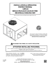
208/230 Volt Single PhasePackaged Two Stage Heat/Two Stage Electric Air Conditioner 60Hz
WIRING DIAGRAM
NOTES:
1. Disconnect power before servicing.
2. For supply connections use copper conductors only.
3. Not suitable on systems that exceed 150V to ground.
NOTES:
1. Couper le courant avant de faire letretien.
2. Employez uniquement des conducteurs en cuivre.
3. Ne convient pas aux installations de plus de 150 V
a la terre.
4. If any of the original wire as supplied with the furnace must be replaced, it
must be replaced with wiring material having a temperature of at least 105°C.
5. For supply wire ampacities and overcurrent protection, see unit rating plate.
6. Ensure that wires from the blower remain connected to the board thermostat
terminals after making the field thermostat connections.
7. Wiring shown for single stage operation. For two
stage operation, move Brown wire from low side
of Gas Valve to W2 on the Terminal Block and
remove the Jumper from W1 to W2.
7110920
(Replaces 708580C)
0310
FIELD WIRING
LEGEND:
LOW VOLTAGE
HIGH VOLTAGE
FAULT CONDITION STATUS LIGHT (RED)
Power On On
Limit Circuit Open 1 Flash
Pressure Switch Stuck Open with Inducer On 2 Flashes
Pressure Switch Stuck Open with Inducer Off 3 Flashes
Ignition Failure (Check Ground) 4 Flashes
230 VAC & Neutral Reversed or No Ground 5 Flashes
False Flame or Gas Relay Shorted Continuous Flash
Power Off Off
FAULT CONDITION STATUS LIGHT (YELLOW)
Low Flame Sensor Signal Continuous Flash
e Present On
/