Spektrum AR7110 7-Channel DSMX Heli Receiver User manual
- Category
- Toy parts
- Type
- User manual
This manual is also suitable for
Page is loading ...

2 3
EN
The following terms are used throughout the product literature to indicate various
levels of potential harm when operating this product:
NOTICE: Procedures, which if not properly followed, create a possibility of
physical property damage AND a little or no possibility of injury.
CAUTION: Procedures, which if not properly followed, create the probability of
physical property damage AND a possibility of serious injury.
WARNING: Procedures, which if not properly followed, create the probability
of property damage, collateral damage, and serious injury OR create a high
probability of superficial injury.
NOTICE
All instructions, warranties and other collateral documents are subject to change
at the sole discretion of Horizon Hobby, Inc. For up-to-date product literature,
visit horizonhobby.com and click on the support tab for this product.
Meaning of Special Language
WARNING: Read the ENTIRE instruction manual to become familiar with
the features of the product before operating. Failure to operate the product
correctly can result in damage to the product, personal property and cause serious
injury.
This is a sophisticated hobby product. It must be operated with caution and
common sense and requires some basic mechanical ability. Failure to operate this
Product in a safe and responsible manner could result in injury or damage to the
product or other property. This product is not intended for use by children without
direct adult supervision. Do not attempt disassembly, use with incompatible com-
ponents or augment product in any way without the approval of Horizon Hobby,
Inc. This manual contains instructions for safety, operation and maintenance. It
is essential to read and follow all the instructions and warnings in the manual,
prior to assembly, setup or use, in order to operate correctly and avoid damage or
serious injury.
WARNING AGAINST COUNTERFEIT PRODUCTS
Thank you for purchasing a genuine Spektrum product. Always purchase from a
Horizon Hobby, Inc. authorized dealer to ensure authentic high-quality Spektrum
product. Horizon Hobby, Inc. disclaims all support and warranty with regards, but
not limited to, compatibility and performance of counterfeit products or products
claiming compatibility with DSM or Spektrum technology.
Age Recommendation: Not for children under 14 years.
This is not a toy.
NOTICE: This product is only intended for use with unmanned, hobby-grade, re-
mote-controlled vehicles and aircraft. Horizon Hobby disclaims all liability outside
of the intended purpose and will not provide warranty service related thereto.
WARRANTY REGISTRATION
Visit www.spektrumrc.com/registration today to register your product.

3
EN
DSMX
®
Spektrum launched the 2.4GHz RC revolution with its DSM2™ technology. Since
then, millions of hobbyists the world over have come to embrace 2.4 as the way
to fly. Spektrum leads the way yet again with DSMX—the world’s first wideband,
frequency-agile 2.4GHz signal protocol.
How Does DSMX Work?
It’s a crowded 2.4GHz world out there and every 2.4GHz system faces the same
challenges. DSMX better equips you for these challenges by combining the superi-
or data capacity and interference resistance of a wideband signal (like that used in
DSM2) with the agility of frequency shifts.
Compared to the wideband signal of DSMX, the narrow band signal of other
frequency hopping 2.4 transmitters is more likely to suffer data loss in the event of
on-channel interference. Think of it as a river vs. a stream. It takes more interferen-
ce to dam a river than it does a stream.
As more and more 2.4 transmitters vie for the same number of available channels,
there is more interference and more of a risk for data loss. By adding the agility
of frequency shifts to the superior interference resistance of a wideband signal,
DSMX is far less likely to suffer significant data loss from on-channel interference.
The result is quicker connection times and superior response in even the most
crowded 2.4GHz environment.
DSMX Operational Differences
DSMX transmitters and receivers function nearly identically to Spektrum DSM2
systems. Binding, setting the failsafe, recording flight log data, as well as general
use of the system is no different than using any current Spektrum system.
Following are the operational differences:
Brownout Detection - Not Available on DSMX Receivers DSM2 receivers feature
Brownout Detection that flashes the receiver’s LED if a power interruption occurs.
While DSMX receivers have QuickConnect
™
technology and recover instantly from
a power interruption, the architecture of DSMX prevents Brownout Detection when
operating in DSMX mode.
Flight Log Recording-Fades Higher than DSM2
Note that DSMX hops through the band while DSM2 finds two quiet channels and
remains on those channels. Consequently because DSMX operates on quiet and
noisy channels, it’s common to have more Antenna Fades than when using DSM2,
when used in busy 2.4GHz environments. When taking flight log data readings, the
Frames and Hold Data are important and should be used a reference while Fades
are insignificant due to the nature of frequency hopping. A 10-minute flight will
typically result in less than 50 Frame Losses and no Holds.
Just How Good is DSMX?
In multiple tests, 100 DSMX systems were operated simultaneously for extended
periods of time. During these tests each of the 100 systems was monitored in flight
and on the ground. In every test not a single case of RF link loss, latency increase
or control degradation was experienced or recorded.

4 5
EN
Is DSMX Compatible with DSM2?
Yes. DSMX is fully compatible with all DSM2 hardware. In fact, many pilots may
find the DSM2 equipment they have now is all they will ever need. Even if a new
DSMX transmitter eventually comes along that they really want, all the DSM2
receivers they have now will work with it.
It is important to note, however, that while DSMX is compatible with DSM2, the
only way to experience the full benefits of DSMX in a busy 2.4 environment is by
pairing a DSMX transmitter with a DSMX receiver.
Are DSM2 Transmitters Eligible for a DSMX Add-on?
Yes. DX8 owners can simply download Spektrum AirWare
™
software from spekt-
rumrc.com and update the firmware using their SD card. All DSM2 transmitters,
except the DX5e, are eligible for the add-on by going to
https://community.spektrumrc.com/ for details. DSM2 receivers and transmitter
modules are not eligible for the DSMX add-on.
Does DSMX have ModelMatch
™
and ServoSync
™
?
Yes. DSMX will provide you with these and other exclusive Spektrum advantages
you already enjoy with DSM2. Want to know more about DSMX? Visit spektrumrc.
com for complete details on this as well as the many other reasons Spektrum is the
leader in 2.4.
Note: DSMX receivers are not compatible with DSM2 remote receivers and DSM2
receivers are not compatible with DSMX remote receivers.
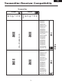
• DSMX transmitters are compatible with all DSM2 and DSMX receivers and will
operate in the mode noted below.
• DSM2 transmitters are compatible with all DSM2 and DSMX receivers and will
operate in the mode noted below.
• DSMX technology is active only when both transmitter and receiver are DSMX
enabled.
Note 1: DSMX upgraded DX5e and DX6i transmitters are compatible with all
DSMX receivers except the high-speed DSM2 receivers (like the AR7600, AR9000,
etc.). When using a high-speed DSM2 receiver with the DX5e or DX6i, it’s
necessary to manually put these transmitters into DSM2 mode. See the Spektrum
website for details on DX5e/DX6i DSM2 mode for details.

5
EN
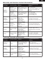
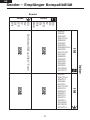
Transmitter-Receiver Compatibility
AR500
AR600
AR6100
AR6110/e
AR6200
AR6255
AR6300
AR6400/ALL
AR7000
AR7100/R
AR7600
AR8000
AR9000
AR9100
AR9200
AR9300
AR12000
AR12110
AR600
AR6115/e
AR6210
AR6255
AR7010
AR7110/R
AR7610
AR8000
AR9010
AR9110
AR9210
AR9310
AR10000
AR12010
AR12110
DX5e
DX6i
DX7
DX7SE
DX8
DX10t
Modules
DX5e
DX6i
DX7
DX7SE
DX8
DX10t
Set Tx to DSM2 only **note 1
DSM2 DSM2
DSM2 DSMX
Transmitter
Receiver
DSM2 DSMX
DSMX DSM2

6 7
EN
AR7110/AR7110R User Guide
Spektrum AR7110 series receivers offer the ultimate system for high-performance
nitro or 500-class and larger electric helicopters. Combining the bullet proof radio
link of Spektrum DSM2 technology with a built-in regulator for the Rudder, Aux2,
Gear and Throttle channels and an integrated RevLimit limiter (AR7110R only), the
AR7110 series receivers make installation of these normally complex devices clean
and simple.
The AR7110 features a Fail-On soft switch to ensure reliability and heavy 16AWG
low resistance input power leads for uninterrupted power even under the most
demanding high-current draw applications. The newly developed backplate rpm
sensor makes this integrated receiver, limiter and regulator system the easiest and
neatest possible to install with only one external rpm sensor lead for the limiter.
Designed and developed by helicopter experts, the all-in-one integrated design
of the AR7110 takes the hassle out of installing and properly setting up separate
receivers, regulators and limiters.
The AR7110/AR7110R full range 7-channel receiver features DSM
®
technology
and is compatible with all Spektrum™ and JR
®
aircraft radios that support DSM2
and DSMX technology including: JR12X, 11X, X9503, X9303, Spektrum DX8,
DX7, DX6i, DX5e and Module Systems.
NOTICE: The AR7110/AR7110R receiver is not compatible with the Spektrum DX6
parkflyer transmitter.
Features
• Regulated 5.2-voltage output to the Rudder, Gear, Aux 2 and Throttle channels
allowing the cyclic servos to be powered at high voltage for increased
performance while the gyro and throttle servos are powered by the necessary
compatible lower voltage (5.2V).
• AR7110R incorporates an integrated RevLimit limiter with backplate rpm sensor
offering the cleanest, easiest installation available.
• Easy-to-mount backplate RevLimit rpm sensor—with a single lead that plugs
into the receiver, eliminates the hassle of mounting magnets and brackets as is
the case for typical rpm sensors.
• Heavy-duty 16AWG input leads pre-wired with EC3 connector.
• Dual outputs on the Throttle and Aux 2 channels (regulated to 5.2 volts/
unregulated).
• One internal receiver and up to two remote receivers.
• Soft switch fails-on if the switch is damaged.
• Optional charge ON/OFF adaptor lead (included) allows charging, battery
monitoring and ON/OFF through one easily accessible lead.
• Two types of failsafe—SmartSafe (throttle only) and conventional failsafe (all
servos).
• QuickConnect - If a power interruption (brown out) occurs the system
reconnects in less than .25 seconds.
• Flight Log compatible.
•Compatible with all Spektrum and JR DSM2 full range radio systems.
• 2048 Resolution

7
EN
Note: The AR7110/AR7110R uses a specifically designed switch. Conventionally
wired switches are not compatible with the AR7110.
IMPORTANT: The AR7110 and AR7110R require that at least one remote receiver
(included) be plugged into port B or R to operate.
Applications
• All sizes of nitro powered helicopters
• 500-class and larger electric helicopters
Specifications:
AR7110/AR7110R
Type: DSM Full Range receiver
Channels: 7
Modulation: DSM2, DSMX
Dimensions: 1.86 in x 1.58 in x 0.56 in (47.3mm x 40.2mm x 14.2mm)
Weight: 1.1 oz (32.5 g)
Voltage range: 6.0 to 10.0 volts/ 5 to 7 cell NiMH or 2-cell LiPo*
Minimum receiver operational voltage: 3.5 volts
Minimum regulator operational voltage: 5.5 volts
Output voltage: Rudder, Aux 2, Throttle 2, Gear 2 = 5.2 volts/ all other channels
unregulated (for high voltage compatible servos only)
Max regulated channel current: 2 amp continuous
Resolution: 2048
Switch: Soft Switch (Switch port can also be used with charge adaptors
Connector type: EC3
™
Remote Receiver
Dimensions LxWxH: 1.02 in x 0.80 in x 0.27 in (25.8mm x 20.2mm x 6.8mm)
Weight: 0.1 oz (5.0 g)
CAUTION: When the battery is connected to the AR7110/AR7110R a low
current drain of less than 1mA occurs even when the soft switch is turned
off. If the system is going to be stored for any length of time it’s important that the
battery be disconnected from the AR7110 to prevent overdischarge.
Items Included
SPMAR7110/SPMAR7110R AR7110/AR7110R Receiver
SPM9545 Remote Receiver
SPM9011 9-inch Remote Extension Lead
SPM6820 Soft Switch
SPM6821 Charge ON/OFF Adaptor Lead
SPM6823 Backplate Rpm Sensor (AR7110R only)
SPM6803 Bind Plug
Instruction Manual

8 9
EN
Battery Requirements
IMPORTANT: DO NOT use a 4-cell 4.8-volt battery to power the AR7110/
AR7110R.
Because of the built-in regulator the AR7110/AR7110R has a minimum recommen-
ded operational battery voltage of 5.5 volts and is designed to use 6-volt 5-cell
NiMH, 7.2-volts 6-cell NiMH or 7.4-volt 2-cell LiPo batteries. (Higher voltage
should be used only if the servos are compatible.) While the AR7110 will continue
to operate down to 3.5 volts, the AR7110/ AR7110R features a built-in 5.2-volt
regulator for the Rudder, Aux 2, Gear 2, Throttle 2 channels output. A 4-cell
4.8-volt battery will not provide sufficient headroom (voltage margin) to maintain a
5.2 regulated voltage. Regulated outputs are provided to allow the gyro, gyro gain
and throttle to be operated at the necessary lower voltage while the cyclic servos
(aileron, elevator and pitch) are powered directly by the pack voltage (typically
5-cell 6-volt NiMH or if high voltage compatible servos are used 2-cell 7.4-volt
LiPo batteries).
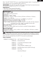
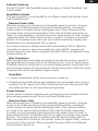
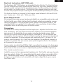
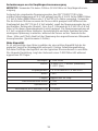
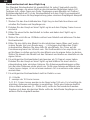
Battery Capacity
It is important to select a battery that has more than adequate capacity to provide
the necessary flight time. Our staff has been recording in-flight data to determine
typical current consumption of aircraft in flight. The following graph illustrates a
T-REX Nitro 600 during aggressive 3D flight.
Helicopter T-REX 600N
Servos 3-JR8717’s, 1-8900G (rudder),
1-8317 (throttle)
Batteries 1- 2100mAh 2-cell 7.4-volt LiPo
Engine YS50
Flight envelope Aggressive 3D
Average current 1.15 amps
Peak current 3.33 amps
Milliamps used per 8 minute flight 173mAh

9
EN
In the above example the average current was 1.15 amps, which calculates to
153mAh per 8 minutes (typical flight length). It’s recommended that only 60%
of the available capacity be used to ensure plenty of reserve battery capacity. In
this example using 2000mAh batteries 2000 x 60% = 1200mAh (available usable
capacity) divided by the capacity used per 8 minute flight, 153mAh would allow up
to 7 flights of 8 minutes each.
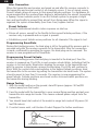
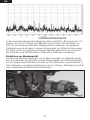
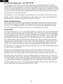
Recommended Guidelines for Battery Capacity
For 50-size electric and glow powered helicopters a minimum capacity of
2000mAh is recommended. For 90-size helicopters a minimum of 3000mAh is
recommended. Our staff uses 2000mAh LiPos in 50-size helis and 4000mAh LiPos
in 90-size machines and typically flies 4 or 5 flights then recharges. Following is a
picture of a typically recommended installation.

10 11
EN
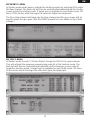
Installation
• Mount the Receiver unit in the position recommended by the helicopter manu-
facturer. Foam or thick double-sided tape is recommended to isolate the receiver
from vibration.
• Mount the switch and insert the switch plug into the port in the main unit marked
SWITCH. Note: The AR7110/AR7110R uses a specifically designed switch.
Conventionally wired switches are not compatible with the AR7110.
• Using the battery capacity guidelines select the battery system that best ts
your application and install the battery in your heli. Connect the battery to the
receiver’s EC3 connector. Spektrum batteries are pre-wired with an EC3 conne-
ctor and plug directly in. If using another brand of battery it will be necessary to
solder EC3 connectors to the battery leads.
• Using double-sided foam tape and tie wrap, mount a minimum of 1 and up to
2 remote receivers in your aircraft and plug them into the receiver ports. NOTE:
It’s necessary that one receiver be plugged into port B or R in order to operate.
The receiver should be mounted at least 2” away from the main receiver with the
antennas perpendicular.
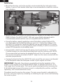
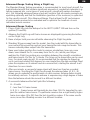
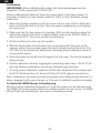
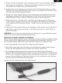
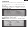
• If using the RevLimit Limiter (AR7110R only) mount the rpm sensor and bracket
to the backplate under two backplate screws of your engine as shown.
IMPORTANT: Normally, the pickup is mounted touching the backplate of the
engine. If your system is not limiting RPM in flight, re-position the sensor .5 to
1mm away from the back plate. This can be easily accomplished by loosening the
2-56 button head screw on the sensor mount, re-adjusting the position, and then
tightening. This should resolve the issue.
Threadlock must be used on the screws. The rpm sensor bracket is adjustable for
50-size or 90-size engines by extending or retracting the rpm sensor and fastening
the screw in place.

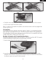
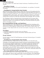
11
EN
Bracket adjusted for 50-size engineBracket adjusted for 90-size engine
• Plug the servo leads and rpm sensor into the appropriate ports in the receiver.
• You are now ready to bind the system.
Note: In order for the system to operate, one remote receiver must be plugged into
receiver port B or R.
Connections
The throttle and gear channels have two outputs. Output 1 is unregulated and the
pack voltage is provided at this port. Throttle and Gear outputs 2 are regulated to
5.2 volts when a throttle servo and gyro are used that are not compatible with high
voltage. Most gyros require less than 6 volts.
Binding Telemetry with PowerSafe Receivers
Spektrum PowerSafe receivers like the AR9110, AR12110 and the AR7110 require
a special binding procedure when using telemetry modules.
1. Insert a bind plug in the bind port in the receiver.
2. Insert the telemetry modules’ Data port lead into any un-used channel in the
receiver. (If all channels are being used remove any servo lead from the receiver
to allow an open servo port to be accessed).

12 13
EN
3. Power the receiver through the EC3 connector. Note all of the receivers
(internal and remote) should be flashing indicating they are in bind mode.
4. Using a second battery, insert the battery plug into any un-used channel in the
receiver while pressing and holding the bind button on the side of the telemetry
module. This will place the telemetry module in bind mode.
5. Make sure that the LEDs are flashing on all receivers and on the telemetry
module. Place the all channels (sticks and switches) on the transmitter in the
desired failsafe position. Now bind the transmitter to the system.
6. Remove the second battery from the receiver, remove the bind plug and move
the telemetry module connector to the bind port to allow flight log data to be
displayed.
NOTICE: Do not leave the secondary battery plugged in for more than a few
minutes as damage to the battery can occur.
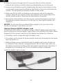
Optional Charge ON/OFF Adaptor Lead
Included with the system is an optional charge, ON/OFF adaptor lead. Some heli
pilots may prefer to use this adaptor lead instead of the included Soft Switch. When
plugged into the receiver’s switch port this adaptor lead allows the following:
• The battery can be charged through the adaptor lead.
• The system can be turned off by inserting the bind plug. Removing the bind plug
turns the system on.
• Battery voltage can be monitored through the adaptor lead using a Flight Log
or voltmeter. If the voltmeter is plugged directly into the male-male extension,
the system is active and voltage under load (system operational) is displayed. If
plugged into the charging lead, the at-rest battery voltage is displayed.
Install the adaptor lead as shown:

13
EN
Failsafe Functions
The AR7110/AR7110R PowerSafe features two types of failsafe: SmartSafe
™
and
Preset Failsafe.
SmartSafe Failsafe
This type of failsafe is recommended for most types of giant-scale aircraft. Here’s
how SmartSafe works:
Receiver Power Only
When the receiver only is turned on (no transmitter signal is present), all servos
except for the throttle are driven to their preset failsafe positions, normally all
control surfaces at neutral and the landing gear down. These failsafe positions
are stored in the receiver during binding. At this time the throttle channel has no
output, to avoid operating or arming an electronic speed control (if used). In glow-
-powered models, the throttle servo receives no input so it remains in its current
position. Some analog servos will coast (move when powered up) slightly even
though there is no signal present. This is normal.
The receivers remain in standby mode with the blue battery LEDs lit. When the
transmitter is turned on, the receiver locates the signal (GUID), connects and
normal control resumes. When connected, the amber LEDs on all attached remote
receivers will be on.
After Connection
When the transmitter and receiver are turned on and after the receiver connects to
the transmitter and normal control of all channels occurs, if loss of signal occurs,
SmartSafe drives the throttle servo to its preset failsafe position (low throttle) that
was set during binding. All other channels hold their last position. When the signal
is regained, the system immediately regains control.
SmartSafe:
• Prevents unintentional electric motor response on start-up.
• Establishes low-throttle failsafe and maintains last-commanded control surface
position if the RF signal is lost. Note: Failsafe positions are stored via the stick
and switch positions on the transmitter during binding.
Preset Failsafe
Preset Failsafe is ideal for sailplanes and is preferred by some modelers for their
glow and gas powered aircraft. Here’s how Preset Failsafe works.
Receiver Power Only
When the receiver only is turned on (no transmitter signal is present), all servos
except for the throttle are driven to their preset failsafe positions, normally all
control surfaces at neutral and the landing gear down. These failsafe positions
are stored in the receiver during binding. At this time the throttle channel has
no output, to avoid operating or arming an electronic speed control (if used). In
glow-powered models, the throttle servo has no input so it remains in its current
position. The receiver remains in standby mode with the blue battery LEDs lit.
When the transmitter is turned on, the receiver locates the signal (GUID), connects
and normal control resumes. When connected, the amber LEDs on all attached
remote receivers will be on.

14 15
EN
After Connection
When the transmitter and receiver are turned on and after the receiver connects to
the transmitter and normal control of all channels occurs, if loss of signal occurs
Preset Failsafe drives all servos to their preset failsafe positions. For sailplanes it’s
recommended that the spoilers/flaps deploy to dethermalize the aircraft, preventing
a flyaway. Some modelers prefer to use this failsafe system to program a slight
turn and low throttle to prevent their aircraft from flying away. When the signal is
regained, the system immediately (less than 4 ms) regains control.
Preset Failsafe:
• Prevents unintentional electric motor response on start-up.
• Drives all servos, except for the throttle to their preset failsafe positions, if the
receiver only is powered and no signal is present.
• Establishes preset failsafe servo positions for all channels if the signal is lost.
Programming SmartSafe
During the binding process, the bind plug is left in throughout the process and is
removed only after the receiver connects to the transmitter. After the connection
is made, confirmed by operating the servos, the bind plug can be removed. The
receiver is now programmed for SmartSafe.
Programming Preset Failsafe
During the binding process the bind plug is inserted in the bind port, then the
receiver is powered up. The LEDs in each receiver should blink, indicating that the
receiver is in bind mode. Now before binding the receiver to the transmitter and
with the receiver in bind mode, remove the bind plug. The LEDs will continue to
blink. With the control sticks and switches in the desired failsafe positions, bind
the transmitter to the receiver by putting the transmitter into bind mode. The system
should connect in less than 15 seconds. The receiver is now programmed for
preset failsafe. Failsafe positions are stored via the stick and switch positions on
the transmitter during binding.
Range Testing
1. With the model resting on the ground, stand 30 paces (approx. 90 feet/28
meters) away from the model.
2. Face the model with the transmitter in your normal flying position and put your
transmitter into range test mode. This causes reduced power output from the
transmitter.
3. You should have total control of the model in range test mode at 30 paces (90
feet/28 meters).
4. If control issues exist, call Horizon Product Support for further assistance.
Press and hold the bind button
30 paces (90 feet/28 meters)

15
EN
Advanced Range Testing Using a Flight Log
The Standard Range Testing procedure is recommended for most sport aircraft. For
sophisticated aircraft that contain significant amounts of conductive materials (e.g.
turbine powered jets, some types of scale aircraft, aircraft with carbon fuselages,
etc.), the following advanced range check will confirm that all remote receivers are
operating optimally and that the installation (position of the receivers) is optimized
for the specific aircraft. This Advanced Range Check allows the RF performance
of each remote receiver to be evaluated and to optimize the locations of each
individual remote receiver.
Advanced Range Testing
1. Plug a Flight Log into the data port in the AR7110/AR7110R and turn on the
system (Tx and Rx).
2. Advance the Flight Log until frame losses are displayed by pressing the button
on the Flight Log.
3. Have a helper hold your aircraft while observing the Flight Log data.
4. Standing 30 paces away from the model, face the model with the transmitter in
your normal flying position and put your transmitter into range test mode. This
causes reduced power output from the transmitter.
5. Have your helper position the model in various orientations (nose up, nose
down, nose toward the Tx, nose away from the Tx, etc.) while your helper
watches the Flight Log noting any correlation between the aircraft’s orientation
and frame losses. Do this for 1 minute. The timer on the transmitter can be used
here. For giant-scale aircraft, it’s recommended that the airplane be tipped up
on its nose and rotated 360 degrees for one minute then the data recorded. Next
place the airplane on its wheels and do a second test, rotating the aircraft in all
directions for one minute.
6. After one minute, a successful range check will have less than ten recorded
frame losses. Scrolling the Flight Log through the antenna fades (A, B, L, R)
allows you to evaluate the performance of each receiver. Antenna fades should
be relatively uniform. If a specific antenna is experiencing a high degree of fades
then that antenna should be moved to a different location.
7. A successful advanced test will yield the following:
H - 0 holds
F - less than 10 frame losses
A, B, R, L - Frame losses will typically be less than 100. It’s important to com-
pare the relative frame losses. If a particular receiver has a significantly higher
frame loss value (2 to 3X) then the test should be redone. If the same results
occur, move the offending receiver to a different location.

16 17
EN
Flight Log
The Spektrum Flight Log (SPM9540) is compatible with the AR7110/AR7110R
PowerSafe.
The Flight Log displays overall RF link performance as well as the individual
internal and external receiver link data. Additionally it displays receiver voltage.
Using the Flight Log
After a flight and before turning off the receiver or transmitter, plug the Flight Log
into the Data port on the PowerSafe. The screen will automatically display voltage
e.g. 6v2= 6.2 volts.
When the voltage reaches 4.8 volts or less, the screen will flash indicating low
voltage.
Press the button to display the following information:
A - Antenna fades on antenna A B - Antenna fades on antenna B
L - Antenna fades on the left antenna R - Antenna fades on the right antenna
F - Frame loss H - Holds
Antenna fades—represents the loss of a bit of information on that specific antenna.
Typically it’s normal to have as many as 50 to 100 antenna fades during a flight.
If any single antenna experiences over 500 fades in a single flight, the antenna
should be repositioned in the aircraft to optimize the RF link.
Frame loss—represents simultaneous antenna fades on all attached receivers. If
the RF link is performing optimally, frame losses per flight should be less than 20.
The antenna fades that caused the frame loss are recorded and will be added to the
total antenna fades.
A Hold occurs when 45 consecutive frame losses occur. This takes about one
second. If a hold occurs during a flight, it’s important to reevaluate the system,
moving the antennas to different locations and/or checking to be sure the
transmitter and receivers are all working correctly. The frame losses that led to the
hold are not added to the total frame losses.
A servo extension can be used to allow the Flight Log to more conveniently be
plugged in without having to remove the aircraft’s hatch or canopy. On some
models, the Flight Log can be plugged in, attached and left on the model using
double-sided tape. This is common with helicopters, mounting the Flight Log
conveniently to the side frame.

17
EN
RevLimit Instructions (AR7110R only)
The Spektrum AR7110R features an integrated RevLimit limiter. The RevLimit func-
tions as a digital rpm limiter preventing the main rotor from over-speeding. When
the rotor speed is at or below the programmed rpm, throttle position is controlled
via the radio (i.e. throttle curves). The RevLimit only engages when the rotor rpm
exceeds the programmed rpm reducing the throttle position preventing over-speed.
The RevLimit limiter is designed to limit engine speed between 9,500 and 20,500
rpm. Engine rpm = Rotor rpm * Main gear ratio.
Servo Requirements
All common three-wire servos (analog and digital) are compatible and can be used
for the throttle servo. Note that two throttle channel outputs are available: unregu-
lated and regulated. The unregulated throttle operates at the battery voltage. The
regulated throttle is regulated to 5.2 volts and is to be used when a high-voltage
compatible servo is not being used for throttle control.
Connections
The RevLimit is totally integrated and the target rpm is adjusted via the Gear cha-
nnel (channel 5). The only external connection needed is to mount the backplate
rpm sensor to the backplate of your engine using two backplate screws. Note
that the rpm sensor mount has two positions: extended for .90-size engines and
retracted for .50-size engines. When installed correctly, the rpm sensor should just
contact the backplate. On some engines and specifically the YS .50 and .90, the
sensors must be spaced .5 to 1mm from the backplate. No additional magnets or
brackets are needed. The rpm sensor picks up the magnetic effect of the crankpin
as it passes the rpm sensor.
If your system is not limiting RPM in flight, re-position the sensor .5 to 1mm away
from the backplate. This can be easily accomplished by loosening the 2-56 button
head screw on the sensor mount, re-adjusting the position, and then tightening.
This should resolve the issue.
Install the servos in their appropriately labeled ports. The throttle and gear channels
have two outputs. Output 1 is unregulated and the pack voltage is provided at this
port. Throttle and Gear outputs 2 are regulated to 5.2 volts when a throttle servo
and gyro are used that are not compatible with high voltage. Most gyros require
less than 6 volts.

18 19
EN
Modes of Operation
The RevLimit target rpm is adjusted thru the Gear channel (channel 5) output.
DX7
In system setup mode program AUX2 to GYRO and GEAR to AUX2, the RevLimit
will be controlled and adjusted via the AUX2 switch, and all the target rpm’s will be
adjusted using the GEAR channel travel adjust.
The Gyro Gain channel will plug into the AUX2 channel and the gyro screen will
be used to adjust the gyro gain (see the DX7 manual for more detail on gyro gain
settings).
In the travel adjust screen two values can be selected that will correspond with
the desired rpm. Note that two different rpms can be selected, or if one value is
programmed to zero, the RevLimit will be turned off when the AUX2 switch is in
that position.
IMPORTANT: When calibrating the system the AUX2 channel must remain at
100% in both directions.

19
EN
JR X9303 2.4GHz
In System mode under device, activate the limiter program by selecting GOV under
the Gear channel. The RevLimit will then be controlled and adjusted via the Limiter
screen located in function mode. A target rpm is available for each flight mode. 0%
turns off the limiter, while the larger the value the higher the target rpm.
The Gyro Gain channel will plug into the Gear channel and the gyro screen will be
used to adjust the gyro gain. (See the X9303 manual for more detail on Gyro Gain
settings.)
JR 12X 2.4GHz
In System mode in code 17 Device Select, Assign the GOV to the gear channel.
This will activate the governor programming code 45 in the function mode. The
RevLimit will then be controlled and adjusted via the Governor screen code 45
located in function mode. A target rpm is available for each flight mode. 0% turns
off the limiter, while the larger the value the higher the target rpm.

20 21
EN
Calibration
IMPORTANT: When calibrating the system, the limiter percentages must be
adjusted to 100% normal and -100% in ST1.
During calibration the RevLimit stores the output limits of the Gear channel. It’s
necessary to adjust the Gear channel output to 100% in both directions during
calibration.
1. Adjust the throttle operation so that the servo travel is near 100% in both direc-
tions at full throttle and at full idle. This may require lengthening or shortening
the servo horn.
2. Make sure that the Gear channel is traveling 100% in both directions when the
switch that controls the limiter is flipped (flight mode on the X9303 2.4GHz or
Aux 2 on the DX7). The servo monitor is helpful here.
3. Set the throttle trim to the low (off) position.
4. With the throttle stick at low throttle, turn on the transmitter then turn on the
receiver; within three seconds toggle the switch that will control the limiter. The
ACT LED on the receiver will flash green indicating that the calibration mode is
successfully entered.
5. Raise and lower the throttle stick throughout its full range. The throttle endpoint
will be stored.
6. Exit the calibration mode by toggling the controlling switch twice. The ACT LED
will stop flashing, indicating a successful calibration was achieved.
7. To verify correct calibration, lower the throttle stick below the 25% position and
the ACT LED should turn off. Above 25% the ACT LED (green) should be on.
Note: Calibration only needs to be performed when first setting up the RevLimit, or
when changing throttle servo throws, or if the unit is installed in another helicopter.
To Verify the RPM Sensor is Functioning
With the system calibrated and turned on, rotate the engine over by hand and note
the SENS LED on the receiver. When the crankpin passes the rpm sensor, the SENS
LED will light red indicating the rpm sensor is working properly.

21
EN
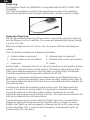
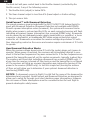
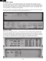
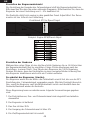
Setting a Target RPM
The Gear channel’s output sets the target rpm. See the diagram below. Note that the
limiter is turned off from 0% to 5% and the target rpm is increased as the travel
adjust/limiter setting is increased. Also note that the rpm increases above and
below 5%. Using the servo monitor is a helpful way of verifying adjustment.
Adjust the gear channel’s travel adjust (DX7) or the limiter program to select the
desired target rpm’s.
Fig: Auxiliary Channel ATV to Target Speed.
Example: Engine RPM/Travel Adjust
Adjusting Throttle Curves
During the initial flights, a slightly elevated throttle curve that will give a headspeed
of approximately 50 rpm above the target rpm is recommended. After operation is
verified, some pilots use a 100% throttle curve in stunt mode and allow the RevLi-
mit to fully regulate the engine rpm. Remember that flipping into normal mode and
low throttle will deactivate the limiter should an issue occur.
How the Limiter Works
The RevLimit waits for the engine to reach the target rpm set by the Gear channel
output. When the target rpm is exceeded, the limiter will smoothly take over the
throttle channel regulating the engine directly. If the rpm drops below the target
speed then normal control will be transferred to the throttle channel.
The RevLimit will only limit the throttle if all of the following conditions have been
met:
1. The rpm sensor, throttle and gear channel are adjusted and operating correctly.
2. The RevLimit has been calibrated.
3. The throttle is above 25%.
4. The gear channel output is greater than 5%.
5. The target rpm has been reached.
Page is loading ...
Page is loading ...
Page is loading ...
Page is loading ...
Page is loading ...
Page is loading ...
Page is loading ...
Page is loading ...
Page is loading ...
Page is loading ...
Page is loading ...
Page is loading ...
Page is loading ...
Page is loading ...
Page is loading ...
Page is loading ...
Page is loading ...
Page is loading ...
Page is loading ...
Page is loading ...
Page is loading ...
Page is loading ...
Page is loading ...
Page is loading ...
Page is loading ...
Page is loading ...
Page is loading ...
Page is loading ...
Page is loading ...
Page is loading ...
Page is loading ...
Page is loading ...
Page is loading ...
Page is loading ...
Page is loading ...
-
 1
1
-
 2
2
-
 3
3
-
 4
4
-
 5
5
-
 6
6
-
 7
7
-
 8
8
-
 9
9
-
 10
10
-
 11
11
-
 12
12
-
 13
13
-
 14
14
-
 15
15
-
 16
16
-
 17
17
-
 18
18
-
 19
19
-
 20
20
-
 21
21
-
 22
22
-
 23
23
-
 24
24
-
 25
25
-
 26
26
-
 27
27
-
 28
28
-
 29
29
-
 30
30
-
 31
31
-
 32
32
-
 33
33
-
 34
34
-
 35
35
-
 36
36
-
 37
37
-
 38
38
-
 39
39
-
 40
40
-
 41
41
-
 42
42
-
 43
43
-
 44
44
-
 45
45
-
 46
46
-
 47
47
-
 48
48
-
 49
49
-
 50
50
-
 51
51
-
 52
52
-
 53
53
-
 54
54
-
 55
55
-
 56
56


Spektrum AR7110 7-Channel DSMX Heli Receiver User manual
- Category
- Toy parts
- Type
- User manual
- This manual is also suitable for
Ask a question and I''ll find the answer in the document
Finding information in a document is now easier with AI
in other languages
Related papers
-
Spektrum Flight Log User manual
-
Spektrum SPM9745 Owner's manual
-
-
Spektrum DX8 Owner's manual
-
-
-
-
-
-
AOR AR7000 User guide
Other documents
-
Blade BLH9319 Owner's manual
-
 Spektrum SMART SPMXSE2125RX Owner's manual
-
-
GRAUPNER MX-10 HOTT User manual
-
HobbyZone HBZ5700 Owner's manual
-
-
E-flite MLP6DSM User manual
-
-
ElectrIQ ELQMEDMA User manual
-
Carson Reflex Wheel Pro Owner's manual
