Page is loading ...

2
EN
The following terms are used throughout the product literature to indicate
various levels of potential harm when operating this product:
NOTICE: Procedures, which if not properly followed, create a possibility of
physical property damage AND a little or no possibility of injury.
CAUTION: Procedures, which if not properly followed, create the probability
of physical property damage AND a possibility of serious injury.
WARNING: Procedures, which if not properly followed, create the probability
of property damage, collateral damage, and serious injury OR create a high
probability of superficial injury.
NOTICE
All instructions, warranties and other collateral documents are subject to
change at the sole discretion of Horizon Hobby, Inc. For up-to-date product
literature, visit horizonhobby.com and click on the support tab for this product.
Meaning of Special Language
WARNING: Read the ENTIRE instruction manual to become familiar
with the features of the product before operating. Failure to operate the
product correctly can result in damage to the product, personal property and
cause serious injury.
This is a sophisticated hobby product. It must be operated with caution and
common sense and requires some basic mechanical ability. Failure to operate
this Product in a safe and responsible manner could result in injury or damage
to the product or other property. This product is not intended for use by
children without direct adult supervision. Do not attempt disassembly, use with
incompatible components or augment product in any way without the approval
of Horizon Hobby, Inc. This manual contains instructions for safety, operation
and maintenance. It is essential to read and follow all the instructions and
warnings in the manual, prior to assembly, setup or use, in order to operate
correctly and avoid damage or serious injury.
Age Recommendation: Not for children under 14 years. This is not a toy.
WARNING AGAINST COUNTERFEIT PRODUCTS
Thank you for purchasing a genuine Spektrum product. Always
purchase from a Horizon Hobby, Inc. authorized dealer to ensure authentic
high-quality Spektrum product. Horizon Hobby, Inc. disclaims all support and
warranty with regards, but not limited to, compatibility and performance of
counterfeit products or products claiming compatibility with DSM or Spektrum.
NOTICE: This product is only intended for use with unmanned, hobby-grade,
remote-controlled vehicles and aircraft. Horizon Hobby disclaims all liability
outside of the intended purpose and will not provide warranty service
related thereto.
WARRANTY REGISTRATION
Visit www.spektrumrc.com/registration today to register your product.

EN
3
DSMX
®
Spektrum launched the 2.4GHz RC revolution with its DSM2 technology. Since
then millions of hobbyists the world over have come to embrace 2.4 as the way
to fly. Spektrum leads the way yet again with DSMX; the world’s first wideband,
frequency-agile 2.4GHz signal protocol.
How Does DSMX Work?
It’s a crowded 2.4GHz world out there and every 2.4GHz system faces the
same challenges. DSMX better equips you for these challenges by combining
the superior data capacity and interference resistance of a wideband signal
(like that used in DSM2) with the agility of frequency shifts.
Compared to the wideband signal of DSMX, the narrow band signal of other
frequency hopping 2.4 transmitters is more likely to suffer data loss in the
event of on-channel interference. Think of it as a river vs. a stream. It takes
more interference to dam a river than it does a stream.
As more and more 2.4 transmitters vie for the same number of available
channels, there is more interference and more of a risk for data loss. By
adding the agility of frequency shifts to the superior interference resistance of
a wideband signal, DSMX is far less likely to suffer significant data loss from
on-channel interference. The result is quicker connection times and superior
response in even the most crowded 2.4GHz environment.
DSMX Operational Differences
DSMX transmitters and receivers function nearly identically to Spektrum
DSM2 systems. Binding, setting the failsafe, recording flight log data, as
well as general use of the system is no different than using any current
Spektrum system.
Following are the operational differences:
Brownout Detection- Not Available on DSMX Receivers
DSM2 receivers feature Brownout Detection that flashes the receiver’s LED if
a power interruption occurs. While DSMX receivers have QuickConnect and
recover instantly from a power interruption, the architecture of DSMX prevents
Brownout Detection when operating in DSMX mode.
Flight Log Recording- Fades Higher than DSM2
Note that DSMX hops through the band while DSM2 finds two quiet channels
and remains on those channels. Consequently because DSMX operates on
quiet and noisy channels, it’s common to have more Antenna Fades than when
using DSM2, when used in busy 2.4GHz environments. When taking flight log
data readings, the Frames and Hold Data are important and should be used
a reference while Fades are insignificant due to the nature of frequency agile
systems. A 10-minute flight will typically result in less than 50 Frame Losses
and no Holds.

4
EN
Just How Good is DSMX?
In multiple tests, 100 DSMX systems were operated simultaneously for
extended periods of time. During these tests each of the 100 systems was
monitored in flight and on the ground. In every test not a single case of RF link
loss, latency increase or control degradation was experienced or recorded.
Is DSMX Compatible with DSM2?
Yes. DSMX is fully compatible with all DSM2 hardware. In fact, many pilots
may find the DSM2 equipment they have now is all they will ever need. Even if
a new DSMX transmitter eventually comes along that they really want, all the
DSM2 receivers they have now will work with it.
It is important to note, however, that while DSMX is compatible with DSM2, the
only way to experience the full benefits of DSMX in a busy 2.4 environment is
by pairing a DSMX transmitter with a DSMX receiver.
Are DSM2 Transmitters Eligible for a DSMX Add-on?
Yes. DX8 owners can simply download Spektrum AirWare
™
software
from spektrumrc.com and update the firmware using their SD card. DX6i
transmitters manufactured after October 2010 can be upgraded using
instructions provided on spektrumrc.com. All DSM2 transmitters, except the
DX5e, are eligible for the add-on for $75 by sending them to the Horizon Hobby
service center. DSM2 receivers and transmitter modules are not eligible for the
DSMX add-on.
Does DSMX have ModelMatch and ServoSync?
Yes. DSMX will provide you with these and other exclusive Spektrum
advantages you already enjoy with DSM2.
Want to know more about DSMX? Visit spektrumrc.com for complete details
on this as well as the many other reasons Spektrum is the leader in 2.4.
NOTICE: While DSMX allows you to use more than 40 transmitters
simultaneously, when using DSM2 receivers, DSMX receivers in DSM2
mode or transmitters in DSM2 mode, do not use more than 40 transmitters
simultaneously.

EN
5
Transmitter-Receiver Compatibility
AR500
AR600
AR6100
AR6110/e
AR6200
AR6255
AR6300
AR6410/ALL
AR7000
AR7100/R
AR7600
AR8000
AR9000
AR9100
AR9200
AR9300
AR12000
AR12100
AR600
AR6115/e
AR6210
AR6255
AR7010
AR7110/R
AR7610
AR8000
AR9010
AR9110
AR9210
AR9310
AR10000
AR12010
AR12110
DX5e
DX6i
DX7
DX7SE
DX8
DX10t
Modules
DX5e
DX6i
DX7
DX7SE
DX8
DX10t
Set Tx to DSM2 only **note 1
DSM2 DSM2
DSM2 DSMX
Transmitter
Receiver
DSM2 DSMX
DSMX DSM2

6
EN
AR9110 Instruction Manual
Features
The Spektrum
™
AR9110 PowerSafe
™
offers the ultimate solution for powering
high-current draw radio systems. In aircraft with multiple high-current draw
servos (e.g. giant-scale aircraft, jets, etc.), the AR9110 PowerSafe can provide
peak current of up to 50 amps and offers true dual battery redundancy and a
fail-on soft switch for the ultimate in reliability. By locating up to four remote
receivers throughout the aircraft, the RF link can be optimized in even the most
demanding aircraft installations that have significant conductive materials like
carbon, stainless steel bypass tubes, tuned exhausts, etc.
• Truedualbatteryredundancy—eachbatteryisisolatedandifonefails/
shorts the other takes over.
• UtilizesuptofourremotereceiversfortheultimateRFlinkineventhemost
demanding applications.
• Upto35ampscontinuousand50ampspeakcurrenthandlingcapability
• Softswitchfails-oniftheswitchisdamaged
• Twotypesoffailsafe:Smartsafe(throttleonly)andpresetfailsafe(allservos)
• QuickConnect:ifapowerinterruption(brownout)occursthesystem
reconnects in less than 1/2 second
• AircraftTelemetryandFlightLogcompatible
• Heavy16AWGdualbatteryleadswithpre-wiredE-ite
®
EC3 connectors
• CompatiblewithallSpektrum
™
and JR
®
full range radio and module
systems
• 2048resolution
Applications
The PowerSafe main unit is not a receiver. The PowerSafe main unit is a power
distribution center that provides up to 35-amps continuous and 50-amps
peak current to power your system. Through extensive testing our engineers
discovered that mounting the receiver in the typical location in sophisticated
aircraft (an aircraft with many high-current draw servos and/or conductive
materials), at the end of the servo and battery leads, is not the optimum
location to provide the clearest RF signal. The AR9110 PowerSafe uses up to
four (a minimum of three are required) remotely mounted receivers that can be
optimally placed in your aircraft providing the best possible RF link in the most
demanding conditions.
• Giant-scaleaircraft
• Jetswithmultiplehigh-currentdrawservos
• Scaleaircraftwithmultiplehigh-currentdrawservosandaccessories
(e.g. lights, ESCs, air valves, etc.)

EN
7
Specifications
PowerSafe Main Unit
Voltage input: 6.0 to 10.0 volts Note: Consult your servo manufacturer’s
specifications for maximum allowable voltage
Minimum operational voltage: 3.5 volts
Continuous current: 35 amps
Peak current: 50 amps
Resolution: 2048
Main unit Dimensions (LxWxH): 1.86 x 1.58 x .56 in (47.3 x 40.2 x 14.2mm)
Weight: 1.2 oz (34 grams)
Connector type: EC3
Regulator: None
Remote Receiver
Dimensions (LxWxH): 1.86 x.1.58 x .56 in (47.3 x 40.2 x 14.2mm)
Weight: 0.2 oz (3 g)
Items Included
• SPMAR9110 PowerSafeMainUnit
• SPM9645 ThreeRemoteReceivers
• SPM6820 SoftSwitch
• SPM9013 One24”RemoteReceiverExtension
• SPM9012 One12”RemoteReceiverExtension
• SPM9011 One9”RemoteReceiverExtension
• SPM6803 Male/femaleBindPlug
• EFLAEC302 TwoEC3BatteryConnectors,Female
• InstructionManual
• TwoChargeReceptacles
Optional Items
• SPMB2150NM 2150mAh6.0VNiMHReceiverPack
• SPMB2700NM 2700mAh6.0VNiMHReceiverPack
• SPMB4500NM 4500mAh6.0VNiMHReceiverPack
• SPMB1350LP LiPoReceiverPack1350mAh
• SPMB2000LP LiPoReceiverpack2000mAh
• SPMB4000LP LiPoReceiverPack4000mAh
• SPMB6000LP LiPoReceiverPack6000mAh
• SPMVR6007 VR6007VoltageRegulator7.5A,6V
• SPM9540 FlightLogDataRecorder
• SPM9548 FullRangeTelemetryModule
• SPM9549 Fly-ByTelemetryModule
• SPM9645 AdditionalRemoteReceiver
• SPM9010 6”RemoteReceiverExtension
• SPM9011 9”RemoteReceiverExtension
• SPM9012 12”RemoteReceiverExtension
• SPM9013 24”RemoteReceiverExtension

8
EN
• SPM9014 36”RemoteReceiverExtension
• SPMEXEC312 12”EC3Extension
• SPMEXEC324 24”EC3Extension
• EFLAEC302 EC3BatteryConnector,Female(2)
Battery Requirements
Using One Battery
The PowerSafe allows the option of using one or two battery packs. When
using one battery simply plug the battery into either one of the two battery
connectors (BATT 1 or BATT2). Be sure to secure the unused battery connector.
Note that the open contacts of the unused battery are not back powered (not
electrically hot), however, the unused connector should be secured to prevent
it from entangling during flight. When the system is powered using one battery,
a single blue LED will constantly emit when the system is powered.
Using Two Batteries
The PowerSafe offers a true redundant dual battery system. When using two
battery packs, each pack functions independently and is isolated from the
other, so that if one pack should fail (open circuit, short circuit, or become
discharged), the other battery will provide power to operate the system.
When using dual batteries it’s important that both batteries be of the same
capacity and ideally of the same age and condition. Note: It’s normal for one
battery to discharge slightly more than the other. This is the nature of a truly
redundant isolated battery system. The battery that has the higher voltage or
lower internal resistance will discharge at a faster rate. Generally the difference
is negligible (less than 10%). Because of this it’s normal for only one blue LED
(Batt 1 or Batt 2) to be on when the system is not under a heavy current load
depending on which pack is providing more power. When using two batteries,
the total available capacity equals the sum total of both batteries e.g.,
BATT1—2000mAh+BATT2-2000mAh=atotalcapacityof4000mAh.
Note:12”and24”EC3batteryextensionsareavailableforinstallations
where the battery is located a distance from the main PowerSafe unit.
Using Dual Voltage Regulators
Spektrum offers a 7.5-amp (11-amp peak) 6.0-volt regulator (SPMVR6007)
specifically designed for use with the AR9110 PowerSafe. Important: When
using two batteries powered through two regulators, each regulator operates
independently and it’s common for one battery to be discharged at a slightly
higher rate depending on the condition of the battery (internal resistance,
voltage, etc.) and the tolerance of the regulators. This causes one battery to
discharge before the other and it’s important to check each battery using a
loaded battery tester (HAN171) at a recommended 1-amp load before each
flight monitoring the voltage of each pack and recharging when the weakest
pack reaches 40% capacity. (See Battery Capacity)

EN
9
Battery Capacity
It’s important to select a battery(s) that has more than adequate capacity to
provide the necessary flight time. Our staff has been recording in-flight data
to determine typical current consumption of aircraft in flight. Following are
two graphs that illustrate the in-flight current draw of the radio system.
Note: Current draws may vary depending on your servos, installation
and flying style.
The following setup is shown as a worst-case scenario indicative of some
aerobatic pilots’ setups. It is not recommended to use this setup without
proper voltage regulation for your servos.
Airplane: 40% YAK
Servos: 9-JR8711’s 1-8317 (throttle)
Batteries: Two 4000mAh 2-cell 7.4-volt LiPos
Regulator: None
Note: JR8711’s and 8317’s are rated at a maximum of 6-volt 5-cell use.
Usinghighervoltageswillvoidthewarranty.
Engine: DA150
Weight: 40 lb
Flight envelope: Hard 3D
Average current: 2.62 amps
Peak current: 17.8 amps
Milliamps used per 10-minute flight: 435mAh
File: JasonNoll.FDR Session:All Sessions
Seconds
35030025020015010050
PackAmps_A
18
17
16
15
14
13
12
11
10
9
8
7
6
5
4
3
2
1
0
PackAmps_A: Mi n 0.00 Ma x 17.80 Avg 2.62
4504000
In the example above, the average current was 2.62 amps, which calculates to
435mAh per 10 minutes (typical flight length). It’s recommended that only 60%
of the available capacity be used to ensure plenty of reserve battery capacity.
In this example using two 4000mAh batteries (8000mAh total capacity) x
60%=4800mAh(availableusablecapacity)dividedbythecapacityusedper
10-minute flight, 435mAh would allow up to 11 flights, of 10 minutes each.

10
EN
Airplane: 33% Sukhoi
Servos: 7-JR8611’s 1-8317 (throttle)
Batteries: one 4000mAh 2-cell 7.4-volt LiPo
Regulator: 6 volt
Engine: DA100
Weight: 26 lb
Flight envelope: Moderate 3D
Average current: 0.82 amps
Peak current: 6.92 amps
Milliamps used per 10-minute flight: 137mAh
File: sukhio Session:All Sessions
PackAmps_A: Min 0.00 Max 6.92 Avg 0.82
Seconds
450400350300250200150100500
PackAmps_A
7
6.5
6
5.5
5
4.5
4
3.5
3
2.5
2
1.5
1
0.5
0
Recommended Guidelines for Battery Capacity
• 40-45%Aerobaticaircraftw/9–12high-currentservos:4000–8000mAh
• 33-35%Aerobaticaircraftw/7–10high-currentservos:3000–6000mAh
• 25%QuarterScaleAerobaticaircraftw/5–7high-currentservos:2000–
4000mAh
• Jets—BVMSuperBANDIT,F86,EuroSport,etc.:3000–6000mAh
• Giant-ScaleJets—BVMUltraBandit:4000–8000mAh
• Scaleaircraft:Thevarietiesofscaleaircraftandtheaccessoriestheyuse
vary tremendously making it difficult to give capacity recommendations for
thesetypesofaircraft.Usingthepreviouslymentionedaerobaticguidelines
relative to the size and number of servos used will provide a conservative
capacity for your scale aircraft. As always, check battery charge condition
before each flight.

EN
11
Battery Voltage
CAUTION: D0 NOT use a 4-cell 4.8-volt battery to power
the PowerSafe.
Four-cell 4.8-volt batteries do not provide enough voltage headroom (additional
marginneeded)necessarytopowerthesystemwhenheavilyloaded.Under
load the system voltage can drop below the voltage system’s minimum
operating voltage threshold (3.5 volts) and cause loss of control. The PowerSafe
is capable of handling voltages from 6.0 to 10.0 volts. The voltage limitations
are generally the servos. Most servos are compatible with 5-cell 6-volt packs.
Five-cell 6-volt NiMH packs have become the standard for many giant-scale
applications.
Be aware that NiMH batteries have a tendency to false peak when
being fast charged. Be especially careful when using NiMH batteries that
they are fully charged and have not false peaked.
Many pilots are using 2-cell LiPo batteries to power their aircraft. LiPos offer
greater capacity for their size and weight, and are easier to manage when
charging. Before using LiPo batteries, please check the voltage specifications
ofyourservos.Useofavoltageregulator,suchastheSpektrumVR6007
(SPMVR6007), might be necessary.
When a battery is connected to the PowerSafe, a low current drain
of less than 1mA occurs even when the switch is turned off. If the system
is going to be stored for any length of time, it’s important that the battery(s) be
disconnected from the PowerSafe to prevent over discharge.
Installation
The PowerSafe requires
a minimum of three
remote receivers to
operate and one receiver
must be plugged into the
A receiver port. Three
remote receivers are
included and in most
cases it is recommended
that three or four receivers
be used. Each receiver
functions independently
and additional receivers
(up to four) offer a more
secure RF link in difficult
environments. The added
security of redundancy
should a failure occur
outweighs the slight
additional weight
and cost penalties.

12
EN
Installing the PowerSafe Main Unit
1. Usingfoamorthickdouble-sidedfoamtapeandtiewraps,securethemain
PowerSafe unit in the position that you would normally mount the receiver.
2. Mount the switch on the side of your aircraft and insert the switch plug
in the port in the main unit marked SWITCH.
Note: The PowerSafe uses a specifically designed switch.
Conventionally wired switches are not compatible with the SmartSafe.
Installing the Batteries
Usingtheaboveguidelinesselectthebatterysystemthatbesttsyour
application and install the battery(s)/regulator(s) in your aircraft. Connect
the battery to the PowerSafe. Spektrum batteries are pre-wired with an EC3
connector and plug directly in. If using another brand of battery it will be
necessary to solder EC3 connectors (two are included with the AR9110)
to the battery leads. If using a regulator, install it per the guidelines
included with the regulator.

EN
13
Mounting the Remote Receivers
Antenna Polarization
For optimum RF link performance it’s important that the remote antennas be
mounted in an orientation that allows for the best possible signal reception
when the aircraft is at all possible attitudes and positions. This is known as
antenna polarization. This allows the greatest exposed visual cross section
of the antennas from all aircraft orientations. If three antennas are used it is
recommended that one antenna be mounted vertically, one horizontally in-
line with the fuselage and one horizontally perpendicular to the fuselage (see
illustrations on pages 11-12). This covers the X,Y and Z axis offering superb
cross section visibility in all aircraft orientations. An optional fourth antenna
can be added at an intermediate angle offering even greater RF link security
and system redundancy.
Locating the Remote Receivers
While Spektrum 2.4GHz systems are far more resistant to interference caused
from internal RF generating sources, the remote receivers should be mounted
asfarawayaspractical(typically4”orgreaterifpossible)fromthefollowing:
• Ignitionsystems
• Ignitionbatteries
• Ignitionswitches
• Engines
• ECU’spumps
• Electricmotors
• Receiverbatteries
• Fueltanks
• Metalbypasstubes
• High-temperature
components like
exhaust systems
• Anysignicant
metallic conductive
components
• High-vibrationareas
Theremoteantennasshouldbemountedaminimumofatleast2”apartfrom
each other as greater antenna separation gives improved path diversity (RF link
performance) in critical environments. In large aircraft where space is not an
issue it is highly recommended that the antennas be mounted throughout the
aircraft as illustrated. Spektrum offers remote receiver extensions ranging from
6”to36”allowingthereceiverstobemountedinthemostoptimumlocations
throughouttheaircraft.Usingdouble-sidedfoamtapeandtiewraps,mount
a minimum of 3 and up to four remote receivers in your aircraft as per the
illustrations and plug them into the receiver ports.
The following are illustrations of typically recommended installations.
Note the remote receiver orientation.
• 35%aerobaticplanewithsingleNiMHbatteryandthreeremotereceivers

14
EN
• 35%aerobaticplanewithdualNiMHbatteriesandthreeremotereceivers
• 40%aerobaticplanewithdualLiPobatteries,dualregulatorsandfour
remote receivers
• JetwithdualLiPobatteries,dualregulatorsandfourremotereceivers
Plugging in the Servos
Plug the servo leads into the appropriate ports in the PowerSafe.
You are now ready to bind the system.
Important: Y-Harnesses and Servo Extensions
When using Y-harnesses or servo extensions, it’s important to use standard
non-amplified Y-harnesses and servo extensions as this can/will cause the
servos to operate erratically or not function at all. Amplified Y-harnesses
were developed several years ago to boost the signal for some older PCM
systems and should not be used with Spektrum equipment. Note that
when converting other models to Spektrum be certain that all amplified
Y-harnesses and/or servo extensions are replaced with conventional,
non-amplified versions.
The JR PCM Y-Harness with Amplifier (JRPA133) is not compatible
with the AR9110 and should not be used.

EN
Binding
Note: In order for the system to operate, one remote receiver must be
plugged into receiver port A and two more receivers must be plugged into
any other ports. When binding the PowerSafe with three remote receivers,
if a fourth remote receiver is added, the system must be re-bound to
recognize the additional remote.
It’s necessary to bind the AR9110 to the transmitter so that the AR9110
will only recognize that specific transmitter, ignoring signals from any other
sources. If the PowerSafe is not bound to the transmitter, the system will
not operate. During binding the servo’s failsafe positions are stored.
How To Bind the PowerSafe
1. With the system hooked up and all remote receivers attached as described
previously, insert the bind plug in the BIND/DATA port in the PowerSafe.
2. Turn on the soft switch. Note that the LEDs on all receivers should
be flashing indicating that the receiver is ready to bind.
3. Establish the desired failsafe stick positions, normally low throttle and flight
controls neutral.
4. Follow the procedures of your transmitter to enter it into bind mode. The
system will connect within a few seconds. The LEDs on all receivers should
go solid, indicating the system has connected.
5. Remove the bind plug and store it in a convenient place.
6. After you’ve programmed your model, it’s important to rebind the system so
the true low throttle and neutral control surface positions are programmed.
Binding Telemetry with PowerSafe
Spektrum PowerSafe receivers like the AR9110, AR12110 and the AR7110
require a special binding procedure when using telemetry modules.
1. Insert a bind plug in the bind port in the receiver.
2. Insert the telemetry modules’ Data port lead into any un-used channel in the
receiver. (Note: If all channels are being used remove any servo lead from
the receiver to allow an open servo port to be accessed).
3. Power the receiver through the EC3 connector. Note that all the receivers
(internal and remote) should be flashing indicating they are in bind mode.

16
EN
4. Usingasecondbattery,insertthebatteryplugintoanyun-usedchannelin
the receiver while pressing and holding the bind button on the side of the
telemetry module. This will place the telemetry module in bind mode.
5. Make sure that the LED’s are flashing on all receivers and on the telemetry
module. Place the all channels (sticks and switches) on the transmitter in
the desired failsafe position. Now bind the transmitter to the system.
6. Remove the second battery from the receiver, remove the bind plug and
move the telemetry module connector to the bind port to allow flight log
data to be displayed.
Note: Do not leave the secondary battery plugged in for more than a few
minutes as damage to the battery can occur.
Failsafe Functions
The AR9110 PowerSafe features two types of failsafe: SmartSafe
™
and Preset Failsafe.
SmartSafe Failsafe
This type of failsafe is recommended for most types of giant-scale aircraft.
Here’s how SmartSafe works.
Receiver Power Only
When the receiver only is turned on (no transmitter signal is present), all
servos except for the throttle are driven to their preset failsafe positions,
normally all control surfaces at neutral and the landing gear down. These
failsafe positions are stored in the receiver during binding. At this time the
throttle channel has no output, to avoid operating or arming an electronic
speed control (if used). In glow-powered models, the throttle servo
receives no input so it remains in its current position.
Note: Some analog servos will coast (move when powered up)
slightly even though there is no signal present. This is normal.
The receiver remains in standby mode with the blue battery LEDs lit. When
thetransmitteristurnedon,thereceiverlocatesthesignal(GUID),connects
and normal control resumes. When connected, the amber LEDs on all
attached remote receivers will be on.
After Connection
When the transmitter and receiver are turned on and after the receiver
connects to the transmitter and normal control of all channels occurs, if loss
of signal occurs, SmartSafe drives the throttle servo to its preset failsafe
position (low throttle) that was set during binding. All other channels hold
their last position. When the signal is regained, the system immediately
(less than 4 ms) regains control.
SmartSafe:
• Preventsunintentionalelectricmotorresponseonstart-up.
• Establisheslow-throttlefailsafeandmaintainslast-commandedcontrol
surface position if the RF signal is lost. Note: Failsafe positions are stored
via the stick and switch positions on the transmitter during binding.

EN
Preset Failsafe
Preset Failsafe is ideal for sailplanes and is preferred by some modelers
for their glow and gas powered aircraft. Here’s how Preset Failsafe works.
Receiver Power Only
When the receiver only is turned on (no transmitter signal is present), all
servos except for the throttle are driven to their preset failsafe positions,
normally all control surfaces at neutral and the landing gear down. These
failsafe positions are stored in the receiver during binding. At this time the
throttle channel has no output, to avoid operating or arming an electronic
speed control (if used). In glow-powered models, the throttle servo has no
input so it remains in its current position. The receiver remains in standby
mode with the blue battery LEDs lit. When the transmitter is turned on,
thereceiverlocatesthesignal(GUID),connectsandnormalcontrol
resumes. When connected, the amber LEDs on all attached remote
receivers will be on.
After Connection
When the transmitter and receiver are turned on and after the receiver
connects to the transmitter and normal control of all channels occurs, if
loss of signal occurs Preset Failsafe drives all servos to their preset failsafe
positions. For sailplanes it’s recommended that the spoilers/flaps deploy to
de-thermalize the aircraft, preventing a flyaway. Some modelers prefer to
use this failsafe system to program a slight turn and low throttle to prevent
their aircraft from flying away. When the signal is regained, the system
immediately (less than 4 ms) regains control.
Preset Failsafe:
• Preventsunintentionalelectricmotorresponseonstart-up.
• Drivesallservos,exceptforthethrottletotheirpresetfailsafepositions,
if the receiver only is powered and no signal is present.
• Establishespresetfailsafeservopositionsforallchannelsifthe
signal is lost.
Programming SmartSafe
During the binding process, the bind plug is left in throughout the process
and is removed only after the receiver connects to the transmitter. After the
connection is made, confirmed by operating the servos, the bind plug can
be removed. The receiver is now programmed for SmartSafe.
Programming Preset Failsafe
During the binding process the bind plug is inserted in the bind port,
then the receiver is powered up. The LEDs in each receiver should blink,
indicating that the receiver is in bind mode. Now before binding the receiver
to the transmitter and with the receiver in bind mode, remove the bind plug.
The LEDs will continue to blink. With the control sticks and switches in the
desired failsafe positions, bind the transmitter to the receiver by putting
the transmitter into bind mode. The system should connect in less than
15 seconds. The receiver is now programmed for preset failsafe.
Note: Failsafe positions are stored via the stick and switch positions
on the transmitter during binding.

18
EN
Standard Range Testing
Before each flying session, and especially with a new model, it’s important to
perform a range check. All Spektrum aircraft transmitters incorporate a range
testing system, which reduces the output power allowing a range check.
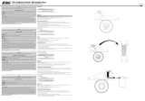
Range Testing
1. With the model resting on the ground,
stand 30 paces (approx. 90 feet/28
meters) away from the model.
2. Face the model with the transmitter
in your normal flying position and put
your transmitter into range test mode.
This causes reduced power output
from the transmitter.
3. You should have total control of the model in range test mode at 30 paces
(90 feet/28 meters).
4. If control issues exist, call the appropriate Horizon Product Support
department for further assistance.
Advanced Range Testing Using a Flight Log
The Standard Range Testing procedure is recommended for most sport aircraft.
For sophisticated aircraft that contain significant amounts of conductive
materials (e.g. turbine powered jets, some types of scale aircraft, aircraft with
carbon fuselages, etc.), the following advanced range check will confirm that
all remote receivers are operating optimally and that the installation (position of
the receivers) is optimized for the specific aircraft. This Advanced Range Check
allows the RF performance of each remote receiver to be evaluated and to
optimize the locations of each individual remote receiver.
Advanced Range Testing
1. Plug a Flight Log into the data port in the AR9110 and turn on the system
(Transmitter and Receiver).
2. Advance the Flight Log until frame losses are displayed by pressing
the button on the Flight Log.
3. Have a helper hold your aircraft while observing the Flight Log data.
4. Standing 30 paces away from the model, face the model with the
transmitter in your normal flying position and put your transmitter into
range test mode. This causes reduced power output from the transmitter.
5. Have your helper position the model in various orientations (nose up,
nose down, nose toward the Tx, nose away from the Tx, etc.) while your
helper watches the Flight Log noting any correlation between the aircraft’s
orientation and frame losses. Do this for 1 minute. The timer on the
transmitter can be used here. For giant-scale aircraft it’s recommended
that the airplane be tipped up on its nose and rotated 360 degrees for
one minute then the data recorded. Next place the airplane on its wheels
and do a second test rotating the aircraft in all directions for one minute.
30 paces (90 feet/28 meters)

EN
19
6. After one minute, a successful range check will have less than ten recorded
frame losses. Scrolling the Flight Log through the antenna fades (A, B, L,
R) allows you to evaluate the performance of each receiver. Antenna fades
should be relatively uniform. If a specific antenna is experiencing a high
degree of fades then that antenna should be moved to a different location.
7. A successful advanced test will yield the following:
0 holds
less than 10 frame losses
Frame losses will typically be less than 100. It’s important to
compare the relative frame losses. If a particular receiver has
a significantly higher frame loss value (2 to 3X) then the test
should be redone and if the same results occur, move the
offending receiver to a different location.
H
F
A, B, R, L
Flight Log
The Spektrum Flight Log (SPM9540) is compatible with the AR9110
PowerSafe. The Flight Log displays overall RF link performance as well
as the individual internal and external receiver link data. Additionally it
displays receiver voltage.
Using the Flight Log
After a flight and before turning
off the receiver or transmitter, plug
the Flight Log into the Data port
on the PowerSafe. The screen will
automatically display voltage e.g.
6v2=6.2volts.
Note: When the voltage reaches
4.8 volts or less, the screen will
flash indicating low voltage.
Press the button to display the following information:
A Antenna fades on internal antenna A
B Antenna fades on internal antenna B
L Antenna fades on the left external
antenna
R Antenna fades on the
right external antenna
F Frame loss
H Holds
Antennafades—representsthelossofabitofinformationonthatspecic
antenna. Typically it’s normal to have as many as 50 to 100 antenna fades
during a flight. If any single antenna experiences over 500 fades in a single
flight, the antenna should be repositioned in the aircraft to optimize the RF link.
Frameloss—representssimultaneousantennafadesonallattachedreceivers.
If the RF link is performing optimally, frame losses per flight should be less than
20. The antenna fades that caused the frame loss are recorded and will be
added to the total antenna fades.
A Hold occurs when 45 consecutive frame losses occur. This takes about one
second. If a hold occurs during a flight, it’s important to reevaluate the system,
moving the antennas to different locations and/or checking to be sure the

20
EN
transmitter and receivers are all working correctly. The frame losses that
led to the hold are not added to the total frame losses.
Note: A servo extension can be used to allow the Flight Log to more
conveniently be plugged in without having to remove the aircraft’s hatch or
canopy. On some models, the Flight Log can be plugged in, attached and
left on the model using double-sided tape. This is common with helicopters,
mounting the Flight Log conveniently to the side frame.
QuickConnect
™
with Brownout Detection
(Brownout Detection not available with DSMX)
The remote receivers now included with the AR9110 feature QuickConnect
with Brownout Detection (Brownout Detection not available with DSMX). Should
a power interruption occur (brownout), the system will reconnect immediately
when power is restored and the LEDs on each connected receiver will flash
indicating a brownout (power interruption) has occurred. Brownouts can be
caused by an inadequate power supply (weak battery or regulator), a loose
connector, a bad switch, an inadequate BEC when using an electronic speed
controller, etc. Brownouts occur when the receiver voltage drops below 3.2
volts thus interrupting control as the servos and receiver require a minimum
of 3.2 volts to operate.
How Brownout Detection Works
When the receiver voltage drops below 3.2 volts the system drops out (ceases
to operate). When power is restored, the receivers will immediately attempt
to reconnect transmitter was left on, the system reconnects, typically about
4ms. The receivers will then blink indicating a brownout has occurred (DSM2
only). If at any time the receiver is turned off then back on and the transmitter
is not turned off, the receivers will blink as a power interruption was induced
by turning off the power to the receiver (DSM2 only). In fact this simple test
(turning the receiver off then on) will allow you to determine if your system’s
brownout detection is functioning.
Note: If a brownout occurs in-flight it is vital that the cause of the brownout
be determined and corrected. QuickConnect is designed to allow you to
safely fly through most short duration power interruptions. However, the
root cause of these interruptions must be corrected before the next flight
to prevent catastrophic safety issues.

EN
21
2.4GHz Troubleshooting Guide
Problem Possible Cause Solution
Aircraft will not
“throttle up”but
all other controls
seem to function
User did not lower throttle
trim and throttle stick
prior to initializing the
aircraft
Lower throttle stick and
throttle trim to their lowest
settings
Throttle channel is
reversed. Futaba tran-
smitters (equipped with
Spektrum modules) may
require you to reverse the
throttle channel
Reverse throttle channel
on specific transmitter if
applicable
LED on aircraft
remains flashing
and cannot be
controlled by
transmitter
User did not wait at least
5 seconds after powering
the transmitter prior to
connecting the flight
battery to the aircraft
Unplug, then reconnect flight
battery
User bound the aircraft to
a different transmitter
Rebind aircraft to your desi-
red compatible transmitter
Transmitter was too
close to aircraft during the
initialization process
Move transmitter (powered
on) a few feet from the
aircraft prior to reconnecting
the flight battery
Controls appear
to be reversed
after binding
to a different
transmitter
User did not initially set
up transmitter prior to
binding to the aircraft
See the “Binding” section of
this manual
Aircraft does
not function
after connecting
flight battery and
aircraft smells
burnt
User may have acciden-
tally plugged the flight
battery in with the wrong
polarity
Replace the receiver board
and ensure the RED polarity
marks are facing the same
direction when connecting
the flight battery to the
receiver board
/