Extron CVEQ 100 User manual

Category
Network switches
Type
User manual
Setup Guide CVEQ/SVEQ 100 Series
This guide provides basic instructions for
an experienced installer to set up and operate
the Extron
®
CVEQ 100 Series and the SVEQ 100
Series of line drivers.
C
Installation and service must be performed
by authorized personnel only.
Installation
Step 1 — Turn off the line driver and input/output devices
Turn the input and output devices off and unplug their power cords. Verify that the line
driver is disconnected from the power source before proceeding.
Step 2 — Attach output cables
For the CVEQ 100 Series, connect a composite video output device to the female BNC
connector.
For the SVEQ 100 Series, connect a S-video output device to the female BNC connectors.
For audio output, wire a balanced/unbalanced audio output device to the 3.5 mm, 5-pole,
direct insertion captive screw connector.
Step 3 — Attach input cables
For the CVEQ 100 Series, connect a composite video input source to the connector (RCA
or BNC, depending on model).
For the SVEQ 100 Series, connect an S-video input source to the connector (4-pin mini
DIN or BNCs, depending on model).
For audio input, connect an unbalanced stereo audio source to the left and right RCA
connectors.
Step 4 — Power on the line driver
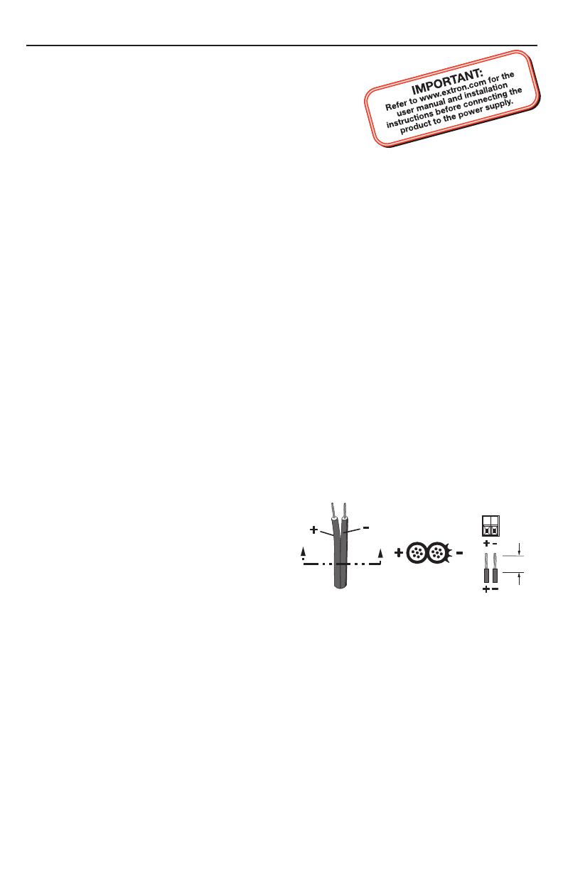
Wire the power connector (see figure 1).
When power is applied to the unit, the
front panel LED lights.
C
Always use a power supply
supplied and or specified
by Extron. Use of an
unauthorized power supply
voids all regulatory compliance
certification and may cause
damage to the supply and the
end product. Unless otherwise
stated, the AC/DC adapters are not suitable for use in air handling spaces or in
wall cavities. The installation must always be in accordance with the applicable
provisions of National Electrical Code ANSI/NFPA 70, article 75 and the Canadian
Electrical Code part 1, section 16. The power supply shall not be permanently fixed
to building structure or similar structure.
Step 5 — Power on devices and check for picture and sound
Connect the power cords and turn on the output devices and input devices.
The picture should appear and sound should be audible. If not, ensure that all devices are
plugged in and receiving power. Check the cabling and make adjustments as needed.
SECTION A–A
Ridges
Smooth
Power Supply
Output Cord
A A
Captive Screw
Connector
3/16”
(5 mm) Max.
Figure 1 – Power connector wiring
Extron USA - West
Headquarters
+800.63 3.9876
Inside USA / Canada Only
+1.714.4 91.1500
+1.714.4 91.1517 FAX
Extron USA - East
+800.63 3.9876
Inside USA / Canada Only
+1.919.86 3.1794
+1.919.86 3.1797 FAX
Extron Europe
+800.39 87.6673
Inside Europe Only
+31.33.453.4040
+31.33.453.4050 FAX
Extron Asia
+800.7339.8766
Inside Asia Only
+65.638 3.44 00
+65.638 3.46 64 FAX
Extron Japan
+81.3.3511.7655
+81.3.3511.7656 FAX
Extron China
+400.883.1568
Inside China Only
+86.21.3760.1568
+86.21.3760.1566 FA X
Extron Middle East
+971.4.2991800
+971.4.2991880 FAX
© 2010 Extron Electronics. All rights reserved.
Setup Guide — CVEQ/SVEQ 100 Series (cont’d)
Step 6 — Adjust video gain and equalization
While watching the display, adjust the video gain and equalization by using the rotary
gain and equalization (EQ) control potentiometers (see figure 2). Make all adjustments
using a small screwdriver. For a more precise setting, use an oscilloscope or a waveform
monitor connected to the far end of the output cable.
CVEQ 100 Series SVEQ 100 Series
If using very short output cables:
Set all potentiometers to the default setting (the arrow on the control pointing to the
dot beside it, as shown in figure 2).
If using longer output cables:
Supply the color bars test signal to the input (Recommendation: use an Extron
VTG 300 Video Test Generator to generate the test signal).
Adjust the gain control(s) for the output until the signal level at the far end is the
same as the input (or the display shows the correct brightness and contrast).
Adjust the EQ control for the output so that no overshoot or round front corner
appears at the far end on the oscilloscope or you see a sharp picture with no
smearing.
Step 7 — Mount the line driver
Make any cabling adjustments before mounting the line driver, as the cables may be
inaccessible afterwards. If necessary, mount the line driver. For mounting information, see
“Installation Instructions” in the CVEQ/SVEQ 100 Series User’s Manual.
Troubleshooting
If the image does not appear or there is no sound
Make sure that all of the devices are powered on.
Ensure that the connectors are wired correctly at both ends of the cables. Audio
cables must be wired for an unbalanced stereo input signal and for the appropriate
(unbalanced or balanced) output signal.
Check the manuals of the output and input devices or contact Extron to determine if
there are special requirements to output video to the external video port.
If the image is not displayed properly
If the picture is too bright or too dark, if the edges of the image seem to exceed their
boundaries, or if thin lines and sharp edges look thick and fuzzy, adjust the gain
setting.
If the picture appears and is stable, but it has ghosting or blooming, verify that the
video input is properly terminated. If the problem is not resolved by changing the
termination, try using a different input cable. Poor quality or damaged cable can
cause ghosting and blooming.
If problems persist, contact the Extron S3 Sales and Technical Support Hotline.
68-1442-50
Rev. A
02 10
Figure 2 – Equalization and gain controls
  • Page 1 1
  • Page 2 2

Extron CVEQ 100 User manual

Category
Network switches
Type
User manual

Ask a question and I''ll find the answer in the document

Finding information in a document is now easier with AI