Page is loading ...

DN1726-0811
KT-400
Ethernet Four-Door Controller
Installation Manual


DN1726-0811
iii
KT-400 Ethernet Four-Door Controller Installation Manual
Table of Contents
Pre-Installation Information ......................................................................................................................... 1
Copyright Information ............................................................................................................................................. 1
Safety Instructions .................................................................................................................................................. 1
Technical Support ....................................................................................................................................... 2
Compliance Specifications .......................................................................................................................... 3
FCC & IC Compliance ................................................................................................................................. 3
UL Compliance ........................................................................................................................................... 3
UL 294 Compliance Notice ......................................................................................................................... 3
UL 1076 Compliance Notice ....................................................................................................................... 3
Overview ..................................................................................................................................................... 5
Compatible with all EntraPass Special, Corporate and Global Editions ..................................................... 5
Multiple Configuration Options .................................................................................................................... 5
Four Onboard doors .................................................................................................................................... 5
Communication Ports .................................................................................................................................. 5
IP Connectivity ............................................................................................................................................ 5
Inputs .......................................................................................................................................................... 6
Lock Outputs ............................................................................................................................................... 6
Relay Outputs ............................................................................................................................................. 6
Reader Outputs ........................................................................................................................................... 6
Reader Interfaces ....................................................................................................................................... 6
Elevator Interface ........................................................................................................................................ 6
Alarm Panel Interface ................................................................................................................................. 6
Automatic Port Detection ............................................................................................................................ 6
Downloadable Firmware ............................................................................................................................. 7
Trouble and Reporting ................................................................................................................................ 7
Visual Status Indicators (LEDs) .................................................................................................................. 7
Built-in SPI Expansion ................................................................................................................................ 7
System Architecture .................................................................................................................................. 11
VITAL LED Heartbeat Patterns ................................................................................................................. 14
Technical Specifications ........................................................................................................................... 15
Electrical Specifications ............................................................................................................................ 16
KT-400 Ethernet Four-Door Controller Models, Expansion Modules Models........................................... 16
Models Information ................................................................................................................................... 18
Installing the KT-400 Ethernet Four-Door Controller ................................................................................. 19
Preparing to Install the KT-400 Ethernet Four-Door Controller ............................................................................ 19
Physical Installation .............................................................................................................................................. 19
Earth Grounding ................................................................................................................................................... 19
Door Locking Devices ........................................................................................................................................... 19
Hooking Up Inputs ................................................................................................................................................ 20
Connect readers and keypads ............................................................................................................................. 20
Relay Controlled Outputs ..................................................................................................................................... 21
Auxiliary Outputs .................................................................................................................................................. 21
Tamper Protection ................................................................................................................................................ 21
Connecting the KT-400 Ethernet Four-Door Controller ............................................................................. 22
Connecting the VC-485 or the USB-485 to the RS-485 Bus ................................................................................ 22
Connecting over Corporate Network (LAN) ..............................................................................................................23
Powering the KT-400 Ethernet Four-Door Controller ................................................................................ 23
SPI Expansion Port ................................................................................................................................... 24
Important Installation Rules about Expansion Modules ............................................................................ 25
Troubleshooting ........................................................................................................................................ 29
Default initialization ................................................................................................................................... 30
How to reset the KT-400 Ethernet Four-Door Controller for Factory Default DHCP mode .................................. 30
KT-400 Ethernet Four-Door Controller Maintenance Recommendations ................................................. 31
Configuring the KT-400 Ethernet Four-Door Controller with the Web Configuration Page ....................... 32
Optional Documentation ....................................................................................................................................... 32

DN1726-0811
iv
Configuring the KT-400 Ethernet Four-Door Controller with the KT-Finder .............................................. 33
Installation Checklist ................................................................................................................................. 37
Inputs and Outputs Assignments Sheet .................................................................................................... 38

DN1726-0811
1
KT-400 Ethernet Four-Door Controller Installation Manual
Pre-Installation Information
To the Installer: If you are familiar with the installation, you can use the installation checklist on page 37 with
the symbol.
Copyright Information
Copyright © 2008 Tyco International Ltd. and its Respective Companies. All Rights Reserved. All specifications were
current as of publication date and are subject to change without notice. EntraPass, Kantech and the Kantech logo are
trademarks of Tyco International Ltd. and its Respective Companies.
Safety Instructions
Important: NEVER INSTALL THE EQUIPMENT DURING A LIGHTNING STORM!
This equipment, KT-400 Ethernet Four-Door Controller, shall be used installed and used within an environment that provides
the pollution degree max 2 and over voltages category II NON HAZARDOUS LOCATIONS, INDOOR only. The equipment is
FIXED and PERMANENTLY CONNECTED and is designed to be installed by Service Persons only; [service person is defined
as a person having the appropriate technical training and experience necessary to be aware of hazards to which that person
may be exposed in performing a task and of measures to minimize the risks to that person or other persons.] The equipment is
installed in a metallic cabinet that meets the applicable requirements for a FIRE ENCLOSURE.
1. The connection to the mains supply must be made as per the local authorities rules and regulations: In the UK as per
BS6701. An appropriate disconnect device must be provided as part of the building installation. Where it is not possible to rely
on the identification of the NEUTRAL in the AC MAINS SUPPLY, the disconnecting device must disconnect both poles
simultaneously (LINE and NEUTRAL).
2. AVOID setting up the equipment near heaters, air conditioners, ventilators, and/or refrigerators;
DO NOT select a place that exposes your controller to direct sunlight, excessive heat, moisture, vapors, chemicals or dust.
3. If during the installation a knockout on the cabinet is removed, it is the installer's responsibility to ensure that the same
degree of protection for the cabinet is provided by the use of bushings, fittings, adequate sealant, etc.
4. The metallic cabinet must be secured to the building structure before operation. Use four (4) stainless steel tapping
screws #8, 32 mm (1.25 in) to mount the cabinet.
5. The ground connection must be as shown within the included diagram, or equivalent.
6. Internal wiring must be routed in a manner that prevents:
- Excessive strain on wire and on terminal connections;
- Loosening of terminal; connections;
- Damage of conductor insulation.
7. It is the end-user and/or installer's responsibility to ensure that the disposal of the used batteries is made according to the
waste recovery and recycling regulations applicable to the intended market.
8. There are no serviceable parts within the equipment; For any issues regarding the equipment please contact your
installer.
9. DISCONNECT POWER BEFORE SERVICING.

DN1726-0811
2
Technical Support
For technical assistance with the KT-400 Ethernet Four-Door Controller and other Kantech products, contact technical
support, Monday to Friday. See the following table for the technical support phone numbers.
Country/Region Phone Numbers
Support
Hours
Email
North America Toll Free +888 222 1560 (GMT -05:00)
US and Canada
Direct: +450 444 2030
Fax: +450 444 2029
8:00 to 20:00 [email protected]
Latin America (GMT -03:00)
Argentina
Direct: +5411 4717 2929
Direct: +5411 4717 1320
Direct: +5411 4717 5525
Fax: +5411 4717 1060
9:00 to 18:00 [email protected]
Asia (GMT +08:00)
Singapore
Direct: +65 6319 9820
Fax: +65 6319 9821
Direct: +65 6389 8297
Fax: +65 6389 8292
8:30 to 18:00
Europe Toll Free +800 CALL TYCO / +800 2255 8926 (GMT +01:00)
Bahrain +800 04127
8:00 to 18:00 [email protected]
France +33 04 72 79 14 83
Greece +00 800 31 22 94 53
Russia +8 10 800 2052 1031
Spain +900 10 19 45
Turkey +00 800 31 92 30 37
United Arab Emirates +800 0 31 0 7123
United Kingdom
+44 08701 ADT SUP / 44 08701 238 787
Direct: +31 475 352 722
Fax: +31 475 352 725

DN1726-0811
3
KT-400 Ethernet Four-Door Controller Installation Manual
Compliance Specifications
FCC & IC Compliance
This device complies with Part 15 of the FCC rules Class A. Operation is subject to the following two conditions: (1) this
device may not cause harmful interference, and (2) this device must accept any interference received including
interference that may cause undesired operation. This class A digital apparatus meets all requirements of the Canadian
Interference Causing Equipment Regulations. The KT-400 Ethernet Four-Door Controller is also compliant with
EN55022:1998, amendment 1:1995, Class A.
UL Compliance
To comply with UL listings, the following requirements must be met:
• Use of a UL listed computer
• Use of UL listed readers (Wiegand 26 and 34 bits, mag stripe 26 and 34 bits, XSF 39 bits have been tested and found to
comply)
• Use of a UL recognized tamper switch on every housing cabinet for the KT-400 Ethernet Four-Door Controller
• Do not use the SmartLink option
• Do not use a 240 VAC transformer (not UL listed)
• Use only UL listed cables
• Use only UL listed adaptors
• Use only a UL listed transformer Hammond BF2F such as Kantech part number TR1675 (Available through Kantech
distributors or dealers, please refer to the Technical Support contact information on page 2 to obtain the specific
transformer)
Note: All circuits are power limited.
UL 294 Compliance Notice
• IP Connectivity: Only for supplementary use when planning to install the KT-400 Ethernet Four-Door Controller with a
UL 294 access control system.
• Use only UL 294 or UL 1076 listed power supply
• Connect Kantech part number KT-ACPW-LED status indicator to the 16 VAC black terminals of the KT-400
• Use Kantech part number KT-BATT-12 battery, see Note.
Note: Backup battery provides operation of up to 12 hours but has been tested for 4 hours per Section 33 of UL 294,
fifth edition.
UL 1076 Compliance Notice
• The KT-400 is UL 1076 Listed as a Commercial Proprietary Control Unit Accessory and Proprietary Burglar Alarm
Unit (Section 83.2), with EntraPass and Redundant Server, alarm system features, KT-300 Controllers, ioProx
Proximity readers, and TRex request to exit devices – other sensor devices (temperature, water level, etc.) may
be used as long as they are also UL 1076 Listed.
• The EntraPass and Redundant Server shall be running at all time, and manned 24 hours a day, 365 days a year
– The EntraPass and Redundant Server will each have their own operator workstation.
• Data processing equipment and office appliance and business equipment used as central supervisory equipment
station shall be listed to Information Technology Equipment - UL 60950.
• Should the EntraPass and/or Redundant Server be replaced, a UL 60950 listed computer must be used.
• The following recommended system requirements apply to the EntraPass Server, Redundant Server, Video Vault,
Card Gateway, SmartLink, and Workstation:
• Operating Systems: Windows® 2000/XP/2003 Standard and Enterprise Server Editions/Vista
• Processor: Pentium IV at 1.8 GHz

DN1726-0811
4
• 1 GB RAM
• Minimum free hard disk space: 20 GB
• Color depth: 24-bit (16 million colors), required for Video Integration only
• Screen resolution: 1024 x 768
• Graphic adapter card: 32 MB
• 48X CD-ROM drive
• Network Interface card: 10/100 Base-T network adaptor
Note: Actual requirements may vary based on your operating system and configuration.
• The Central Supervisory Equipment shall employ supply line transient protection complying with the Standard for
Transient Voltage Surge Suppressors, UL 1449, with a maximum marked rating of 330 V.
• The Central Supervisory Equipment shall employ signal line Transient protection complying with the Standard for
Protectors for Data Communications and Fire Alarm Circuits, UL 497B, with a maximum marked rating of 50 V.
• The Central Supervisory Equipment shall employ that communication circuits and network components
connected to the telecommunications network shall be protected by secondary protectors for communication
circuits. These protectors shall comply with the Standard for Secondary Protectors for Communications Circuits,
UL 497A. These protectors shall be used only in the protected site of the telecommunications network.
• The Central Supervisory Equipment shall be installed in a temperature controlled environment. A temperature
controlled environment is defined as one that can be maintained between 13° - 35°C (55° - 95°F) by HVAC
system. Twenty-four hours on standby power shall be provided for the HVAC system. The standby power system
for the HVAC system may be supplied by an engine driven generator alone. A standby battery is not required to
be used.
• A marking to identify the application and signaling function of the product is located on the inside of the unit (inner
door sticker).
• For certified commercial proprietary control unit accessory applications, the requirements of UL 1076,
Commercial Proprietary Control Unit Accessory also apply.
• Use Kantech part number KT-3LED-PLATE 3-color LED indicators mounted on single plate when the KT-400 is
configured with the (APOU/ALVY) KT-NCC in an EntraPass Global Edition system for remote alarm monitoring.
Refer to the KT-NCC Installation Manual, DN1611 for additional details.
• The reader(s), that is(are) designated to arm or disarm the alarm system, must be within the secured side of the
customer premises.
• The following Kantech readers have been validated by UL for the UL 1076 Standard: P225W26, P225KPW26,
P225XSF, P225KPXSF, P325W26, P325KPW26, P325XSF, P325KPXSF and P600.
Note: All readers can be ordered with or without the following suffixes: BEI, BEI-SE, GRY or GRY-SE.
• The KT-400 Ethernet Four-Door Controller is UL 1076 listed when used with the (APOU/ALVY) KT-NCC (Network
Communications Controller).
• All alarms shall be reported and acknowledged in the following priority:
Note: To set these priorities, please adjust the Event Parameters, found in EntraPass System
1. Fire alarm and industrial supervision where a risk of injury to persons, or damage or destruction of property may be
involved
2. Hold-up or panic alarm
3. Burglar alarm
4. Watchman tour (Guard tour)
5. Fire-alarm supervision
6. Burglar-alarm supervision
7. Industrial supervision where a risk of injury to persons, or damage or destruction of property will not be involved.

DN1726-0811
5
KT-400 Ethernet Four-Door Controller Installation Manual
Overview
The KT-400 Ethernet Four-Door Controller is designed to meet the highest standards of access control and point
monitoring applications. Here are the features of the KT-400 Ethernet Four-Door Controller.
Compatible with all EntraPass Special, Corporate and Global Editions
The KT-400 Ethernet Four-Door Controller is compatible with all EntraPass Editions v4.01 and higher:
- EntraPass Special Edition
- EntraPass Corporate Edition with a Corporate Gateway
- EntraPass Global Edition with a Corporate Gateway
- EntraPass Global Edition with a Global Gateway
- EntraPass Global Edition with a KT-NCC Network Communications Controller
Multiple Configuration Options
- EntraPass: The KT-400 Ethernet Four-Door Controller can be configured with all EntraPass Editions v4.01 and
higher.
- Web Configuration Page: The Web Configuration Page is accessible through any browser. It can be used to verify
and configure the IP settings of the following Kantech devices: the KT-400 Ethernet Four-Door Controller, the KT-
NCC and the Kantech IP Link. Refer to the procedure “Configuring the KT-400 Ethernet Four-Door Controller with
the Web Configuration Page” on page 32 for further details.
- KT-Finder: The KT-Finder is a stand-alone application that can be used to verify and configure the IP settings of the
following Kantech devices: the KT-400 Ethernet Four-Door Controller, the KT-NCC and the Kantech IP Link. The
Kantech device can be located within the same LAN or in a remote location over the internet. Refer to the procedure
“Configuring the KT-400 Ethernet Four-Door Controller with the KT-Finder” on page 33 for further details.
Four Onboard doors
The KT-400 Ethernet Four-Door Controller is a full 4 onboard doors access controller. See Figure 1 for a description of
the PCB and Figure 2 for all the connection possibilities offered by the KT-400 Ethernet Four-Door Controller.
Communication Ports
• 1 10/100Base-T Ethernet for network connection with the EntraPass Gateway
• 1 RS-232 (COM3) for direct connection to the EntraPass Gateway and RS-485 communication with KT-100, KT-200,
KT-300 and KT-400
• 1 RS-485 (COM1) for RS-485 communication between the EntraPass Gateway and the KT-100, KT-200, KT-300 and
KT-400
• 1 SPI (Serial Peripheral Interface) port for expansion modules such as the KT-MOD-REL8 (8-Relay Outputs), the KT-
MOD-INP16 (16-Input) and the KT-MOD-OUT16 (16-Output)
IP Connectivity
The KT-400 Ethernet Four-Door Controller, when used with EntraPass Special Edition or a Corporate Gateway, can
report events, gather its configuration through an IP connection over the LAN (Local Area Network) and over the Internet
for a WAN (Wide Area Network). In this mode, the 1st or local controller becomes a “Master Controller” and can poll up
to 31 Kantech controller(s). The KT-400 Ethernet Four-Door Controller is compatible with all the controllers. Unlike the
other controllers, the KT-400 Ethernet Four-Door Controller asynchronously polls the controllers (KT-100, KT-200, KT-
300) and communicates with the EntraPass Gateway only when necessary. This significantly reduces the amount of
bandwidth required to operate your security system on the network.
• AES Encryption 128-Bit: The KT-400 Ethernet Four-Door Controller is extremely secure. It uses 128-bit AES
encryption to communicate with the Gateway which prevents any hacking from the internet and ensures secure
communications when used over the internet on a wide area network (WAN).

DN1726-0811
6
Inputs
There are 16 onboard inputs on the KT-400 Ethernet Four-Door Controller. Up to 240 more can be added through the
addition of expansion modules, such as the KT-MOD-INP16, for a total of 256 inputs. Each input can be individually
configured for one of the following application:
• Door contact (4 onboard)
• T.Rex (Request to Exit Detector) (4 onboard)
• Interlock (4 onboard)
• Floor Selection for Elevator Application
•Elevator Action
• External Alarm System Status (Armed / Disarmed)
• External Alarm System Alarm (Alarm / Secure)
• External Alarm System Zones
• Relays to trigger on each input in alarm event
• Zone shunt: Single or group of zones can be permanently or temporarily 'shunted' to a secure state on the same
controller. Shunt method includes:
- Zone Shunt by another Zone - When a zone in alarm is programmed to shunt another zone / group of zones.
- Zone Shunt on Unlock - When a zone is temporarily frozen to its actual state (alarm or secured) after an access
granted.
- Manual Shunt - Operator can manually 'Shunt' a zone to a secure state.
- Disarmed Door Shunt - When alarm system is disarmed, some zones may be 'Shunted' to a secure state.
- Entry / Exit Delay Shunt - When a user is in the process of disarming / arming the alarm system and entry / exit
delay prevails, some zones may be 'Shunted' to a secure state.
• Arming / Disarming Request
• Postpone Arming Request
• Tamper switch input: The tamper switch is a non-programmable 'Fixed-Function' input. It is used to identify tampering of
the KT-400 cabinet.
Lock Outputs
There are 4 onboard lock outputs and they are supervised. The locking function can also be performed by any onboard
relay configured for this functionality.
Relay Outputs
There are 4 onboard relay outputs. Up to 256 relay outputs can be supported through the addition of expansion modules
such as the KT-MOD-REL8.
Reader Outputs
There are 4 different possible outputs for each of the 4 onboard reader interfaces for a total of 16 programmable outputs.
Reader outputs are used to give user visual and/or audible feedback on the ongoing access events.
Reader Interfaces
There are 4 onboard reader interfaces. They can be programmed for Wiegand or ABA (Clock and Data) readers.
Elevator Interface
The KT-400 Ethernet Four-Door Controller supports elevator interfacing with the addition of expansion modules such as
the KT-MOD-REL8, KT-MOD-INP16 and KT-MOD-OUT16.
Alarm Panel Interface
The KT-400 Ethernet Four-Door Controller supports alarm panel interfacing with the appropriate connections made
between zone inputs, relay outputs and the alarm system panel.
Automatic Port Detection
The KT-400 Ethernet Four-Door Controller automatically detects the site communication speed set by EntraPass as well
as the communication port which can be IP (ETHERNET #1), RS-485 (COM1) or RS-232 (COM3).

DN1726-0811
7
KT-400 Ethernet Four-Door Controller Installation Manual
Downloadable Firmware
The firmware program can be downloaded from any EntraPass workstation to the KT-400 Ethernet Four-Door Controller.
The firmware program, stored in the controller’s flash memory, is upgraded without having to change any parts.
Trouble and Reporting
The KT-400 Ethernet Four-Door Controller constantly supervises ac power and battery condition and reports “AC Lost”,
“Normal Battery”, “Low Battery”, “Battery Critical” or “No Battery”, status to the EntraPass system. Power outputs are
supervised and electronically protected against short-circuits and surges. Locking devices are also supervised for short
and open circuits.
Visual Status Indicators (LEDs)
The KT-400 Ethernet Four-Door Controller has multiple status indicators such as for troubleshooting, network activity,
power status and outputs activity. See Figure 1 for their locations.
- VITAL or Heartbeat: The VITAL blue LED indicates the communication status with EntraPass or the IP mode of the
controller. Refer to Table 1 for a descriptions of the heartbeat patterns.
- SPI Active (YELLOW): This LED signals activity on the SPI expansion port as well as communication between the
main CPU and the input/output CPU.
- COM1-RX, COM1-TX, COM2-RX, COM2-TX, RS232-RX and RS232-TX (YELLOW): The six serial port LEDs are
transmit/receive activity indicators. The COM2-RX and COM2-TX LEDs are for future use.
- LOCK1, LOCK2, LOCK3 and LOCK4 (RED): Each lock output (Open Drain) has an indicator which turns on each
time the corresponding output is activated.
- RELAY1, RELAY2, RELAY3 and RELAY4 (RED): Each relay output has an indicator which turns on each time the
corresponding relay is activated.
- AC PWR and DC PWR (GREEN): Theses LEDs are on when AC and DC power are present at the AC and/or DC
power input terminals.
- ETH1 LINK (GREEN): The LED is OFF when there is no Ethernet network or the cable is disconnected, and ON
when there is an Ethernet cable and network connection.
- ETH1 TXRX (YELLOW): The LED indicates network activity.
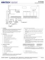
Built-in SPI Expansion
The KT-400 Ethernet Four-Door Controller allows connection of expansion modules in order to add outputs, like relays
and open drain outputs, and inputs. See Figure 10 and Figure 11 for an example with expansion modules.
- KT-MOD-REL8: The KT-MOD-REL8 is an 8-relay expansion module. Each relay is 3 Amps, 30 VDC Form C. The
module supports daisy-chaining which can add up to 32 KT-MOD-REL8 modules for a total of 256 relay outputs per
KT-400 Ethernet Four-Door Controller.
- KT-MOD-INP16: The KT-MOD-INP16 is a 16-zone input expansion module. The module supports daisy-chaining
which can add up to 15 KT-MOD-INP16 for a total of 240 external inputs per KT-400 Ethernet Four-Door Controller.
The KT-400 Ethernet Four-Door Controller has 16 onboard inputs which gives a total of 256 inputs per controller.
- KT-MOD-OUT16: The KT-MOD-OUT16 is a 16-output expansion module. Each output is capable of 750 mA. It
gives the opportunity to address the need for external LED, lock, relay, piezo and buzzer control. The module
supports daisy-chaining which can add up to 16 KT-MOD-OUT16 modules for a total of 256 external open drain
outputs per KT-400 Ethernet Four-Door Controller.
Note: The expansion modules support daisy chaining which can add up to 32 KT-MOD-REL8 modules for a total of 256
external relays per KT-400 Ethernet Four-Door Controller. Combining input and output expansion modules gives the
flexibility to connect up to 256 inputs and 256 outputs.

DN1726-0811
8
Figure 1: KT-400 Ethernet Four-Door Controller PCB View

DN1726-0811
9
KT-400 Ethernet Four-Door Controller Installation Manual
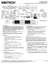
Figure 2: KT-400 Ethernet Four-Door Controller Inputs and Outputs View
10/100 BASE-T ETHERNET PORT
COMPUTER NETWORK
KT-300
KT-100
RS485 BUS (COM1)
TAMPER
NC
C
NC
Z3
NC DRY CONTACT
INPUT DEFINED OPTION
WITH DOUBLE EOL RESISTORS
INPUT DEFINED
RED
BLACK
7 A/H MINIMUM
12V BATTERY
WITH EOL RESISTOR
INPUT DEFINED
DRY CONTACT
NO
OR NC
WITHOUT EOL RESISTOR
DRY CONTACT
NC
OR NO
1200-115200 BAUDS DEVICE
LOW SPEED RS232C
WITH INTEGRATED KEYPAD
IOPROX P325KP READER
BROWN
BLUE
RED (+12V)
BLACK
WHITE
GREEN
BROWN
BLUE
BLACK
RED (+5V)
WHITE
GREEN
POLARIS 2 READER
WITH INTEGRATED
KEYPAD
NO
NC
CZ3
(CONNECT 1K RESISTOR
WHEN INTERNAL PWR USED
12-13.75 VDC, 1 AMP MAX
DOOR LOCKING DEVICE
Z3C Z4
SPI EXPANSION PORT
OPTIONAL
INPUT CONFIGURATIONS
12-28 VDC POWER
LOCKING DEVICES SUPPLY
12-28 VDC, 3 AMPS MAX
OPTIONAL EXTERNAL
IF NOT USED)
OPTIONAL
TAMPER SWITCH
DOOR 1 CONTACT
DOOR 1
REQUEST TO EXIT DEVICE
12VDC PWR
R
R
RS485 from USB-485
USB
ACCESS CONTROL AND INTEGRATED SYSTEMS
TM
POLARIS
*
9 0
7 8
5 6
3 4
1 2
SEALED RECHARGEABLE
BATTERY
12 VOLT
7 AMP/HR
KT-400
ACCESS CONTROL AND INTEGRATED SYSTEMS
KT-300
KT-400
USB-485
0506
+12V-
COM2-RX
RS232-RX
INPUT DOOR 3
COPYRIGHT (C) 2007 TYCO INTERNATIONAL LTD.
RELAY4
RED
EGND
GND+5V
LK4-
LK2-LK1-
BUZ GND
4
GND+LK3-
LOCK
VIN
+
C
TAMP
NC
RS-232
ETHERNET #1
3
C NC NO C NC NO
RELAY
21
CCNCNO NCNO
RELAY
COM2
+485-
AUX
BUZ +12VD1+5V D0 GND GRN YEL
READER DOOR 2
RED BUZD1+5V D0 GRN YEL
READER DOOR 3
RED BUZ +12VD1D0 GRN YEL
READER DOOR 1
RED +12VD1+5V D0 GRN YELDOOR REX Z3 C Z4
INPUT DOOR 1
DOOR C REX Z7 C
Z8
INPUT DOOR 2
DOOR C REX Z11 C Z12 DOOR C REX C Z16
INPUT DOOR 4
READER DOOR 4
Z15
C
P/N:566-472K
REV.:E
+485-
COM1
+12V
HEARTBEAT
SPI ACTIVE
COM1-RX
COM1-TX
COM2-TX
RS232-TX
LOCK4
LOCK3
LOCK2
LOCK1
RELAY3
RELAY2
RELAY1
AC PWR
CPU JTAG
CPLD JTAG
RESET
SPI
LCD MODULE
ETH2 TXRX
ETH2 100
ETH1 TXRX
ETH1 100
GND
EXT | INT
16V
AC
13.75V
DC
+ -
BATT
+
-
DC PWR
Y6
U36
U35
Q56
Q53
Q51
PTF8
PTF7
PTF6
P8
L9
D22
HS3
HS2
HS1
Y3
Y1
Y2
Y4
U13
U26
U9
U20
U22
U2
U28
U24
U17
U6
U14
U5
U25
U7
U3
U23
TR2
TR1
SW2
RV1
R23
R12
Q3
Q4
Q6
Q7
PTF1
PTF3
P3
P6
P2
P1
P5
L1
L5
L4
L2
L3
K2
K4
K1
JP4
JP2 JP3
DL14
DL12
DL18
DL16
DL4
DL3
DL5
DL19
DL17
DL2
DL11
DL8
DL15
DL13
DL7
DL6
DL10
DL9
DL21
DL20
DL1
C27
C28
C29
BT1
P7
J2
J4
R5
D3
CON1
SW1
DL22
EARTH GROUND
CABINET
PEM
LOCKNUT
JUMPER JP4 ON EXT
JUMPER JP4 ON INT
120 VAC, 60 Hz IN
16 VAC, 75 VA OUT
CLASS 2, WIRE-IN

DN1726-0811
10
Figure 3: KT-400 Cabinet Model for North America

DN1726-0811
11
KT-400 Ethernet Four-Door Controller Installation Manual
System Architecture
The KT-400 Ethernet Four-Door Controller can be used through various site applications with EntraPass Special Edition,
EntraPass Corporate Edition and EntraPass Global Edition.
Applications with EntraPass Special Edition and Corporate Edition with Corporate Gateway.
• Over the internet. See Figure 4.
• Over RS-232 with a USB-485. See Figure 5.
Application with EntraPass Global Edition and a Global Gateway.
• Over RS-232 with a VC-485. See Figure 6.
Application with EntraPass Global Edition and a KT-NCC.
• Over the internet with a KT-NCC. See Figure 7.
Application with EntraPass Special Edition, Corporate Edition and Global Edition.
• Over RS-232 straight from EntraPass RS-232 COM port. See Figure 8.
Figure 4: Over the Internet with EntraPass Special Edition and Corporate Edition with Corporate Gateway

DN1726-0811
12
Figure 5: USB-485 with EntraPass Special Edition and Corporate Edition with Corporate Gateway
Figure 6: VC-485 with EntraPass Global Edition and Global or Corporate Gateway

DN1726-0811
13
KT-400 Ethernet Four-Door Controller Installation Manual
Figure 7: Over the internet with a KT-NCC and EntraPass Global Edition
Figure 8: Over RS-232 straight from the EntraPass RS-232 COM port

DN1726-0811
14
VITAL LED Heartbeat Patterns
Communication status and other vital controller parameters can be obtained from VITAL LED heartbeat patterns. It is
located near the RS-232 port (COM3), see Figure 1. This information is particularly useful when connecting the
controller to the rest of the EntraPass system. The following table lists all conditions along with a brief description. Refer
to Table 3, if you must reset or change the communication mode of the KT-400 Ethernet Four-Door Controller.
Table 1: VITAL LED Heartbeat Patterns
Booting Up Steady
Factory Default DHCP Continuous LONG Pulses
Unable to Resolve DNS 2 LONG Pulses
Forced Default Static 3 LONG Pulses
DHCP Server Failed 4 LONG Pulses
Receive Broadcast Single 2.5 Sec. Burst
Card Read or Swipe
Single 0.5 sec burst, resume
previous flash
Hard Reset 4 SHORT Pulses
Corporate Gateway 3 SHORT Pulses
Global Gateway 1 SHORT Pulse
Fail Soft Continuous SHORT Pulses
Firmware Update 5 pulses / sec @ 50% duty cycle
Rebooting 10 pulses / sec @ 50% duty cycle

DN1726-0811
15
KT-400 Ethernet Four-Door Controller Installation Manual
Technical Specifications
Type Description
Power input (KT-400) Transformer class 2, IN 120 VAC; OUT 16 VAC, 75 VA
Battery back-up (KT-BATT-12) 12 VDC, 7 Ah battery supervised, provides up to 12 hours of operation
Operating Temperatures From 2°C to 49°C (35°F to 120°F) indoor use only
Humidity Level 0 to 85% (relative humidity non-condensing).
Cabinet Dimensions
(High-Wide-Deep)
37.59 cm (14.8 in) x 30.48 cm (12.0 in) x 12.57 cm (4.95 in)
Cabinet Weight (KT-400) 4.0 kg (8.82 lb)
PCB dimension 22.86 cm (9 in) X 13.97 cm (5.5 in) X 5.20 cm (2.04 in)
Reader types Wiegand, proximity, ABA Clock and Data, bar code, magnetic, integrated keypad,
smartcard and others
Reader power output 12 VDC and 5 VDC @ 175 mA max each, protected and supervised
Monitored points (inputs) 16 monitored points, single EOL (End of Line), double EOL, without EOL and
1 fixed-function tamper switch input
Points maximum wiring AWG #22 - 600 m (2,000 ft)
Door strike power 12 VDC, 250 mA max for KT-400 supervised
Reader outputs 16 outputs, 25mA max each, open collector outputs
Auxiliary outputs LEDs (LED, OUT1 and OUT2) and buzzer (Buz) for each individual door, 25mA max each,
open collector outputs
Relay controlled output 4 onboard Form C Relay controlled outputs, 30 VDC, 3 Amps max each
Communication ports 1 x RS-232 with RJ-12, 1 x RS-485, 1 x Ethernet 10/100Base-T with RJ-45
Expansion port 1 x SPI 6-pin connector, bidirectional data exchange supported. Supplies 12 VDC, 500 mA
max shared with 12 VDC Auxiliary port
Auxiliary port 1 x Auxiliary 12 VDC, 500 mA maximum shared with SPI expansion port
Communication speed - Up to 115200 Bauds (automatic detection) over RS-232 and RS-485
- 10/100 Mb/s BaseT over Ethernet
Flash memory 16 MB for application storage
RAM memory 64 MB for application loading and running, protected by a Lithium-Ion battery for a
minimum of 75 hours
Network autonomy Distributed data and processing
Certifications / Listing EN55022, EN61000-6-1, EN61000-6-2
FCC: Class A
UL 294, UL 1076

DN1726-0811
16
Electrical Specifications
KT-400 Ethernet Four-Door Controller Models, Expansion Modules Models,
Related Documentation and Miscellaneous Items
OPEN COLLECTOR OUTPUTS MAXIMUM CURRENT
(Typical)
COMBINED MAXIMUM
CURRENT
LEDs (LED, OUT1 and OUT2) for each door reader 25 mA (each)
2 Amps for KT-400
Buzzer (Buz) for each door reader 25 mA (each)
OUTPUTS MAXIMUM CURRENT
1 for 12 VDC Auxiliary Power (11.2 to 13.75 VDC) polyswitch
protected, shared with SPI expansion port
500 mA
4 for Controlled Readers (11.2 to 13.75 VDC) 500 mA
4 for Controlled Readers 5 VDC 400 mA
4 for Locks (11.2 to 13.75 VDC) when jumper JP4 is on INT
(internal)
1 Amp for KT-400
4 for Locks (11.2 to 28 VDC) when jumper JP4 is on EXT
(external)
3 Amp
Part number Description
KT-400 Ethernet Four-Door Controller Models
KT-400 KT-400 Ethernet Four-Door Controller, IP Ready with Accessory Kit in Metal Cabinet, see Table 2
KT-400-PCB KT-400 Ethernet Four-Door Controller PCB only, IP Ready with Accessory Kit, see Table 2
KT-400-CAB KT-400 Black Metal Cabinet with Lock and Keys, see Table 2
Expansion Modules Models
KT-MOD-INP16 KT-400 Expansion Module 16-Zone Inputs with SPI Cable 41 cm (16 in)
KT-MOD-REL8 KT-400 Expansion Module 8-Relay with SPI Cable 41 cm (16 in)
KT-MOD-OUT16 KT-400 Expansion Module 16-Output with SPI Cable 41 cm (16 in)
KT-MOD-CAB KT-400 Expansion Module Cabinet, Black, with SPI Cable 91 cm (36 in), Lock and Two Keys
KT-MOD-SPI16 KT-400 SPI Cable 41 cm (16 in) for SPI Interconnection within the Cabinet
KT-MOD-SPI36 KT-400 SPI Cable 91 cm (36 in) for SPI Interconnection between Cabinets
Related Documentation
DN1420 EntraPass Special Edition, Reference Manual - English version
DN1415 EntraPass Corporate Edition, Reference Manual - English version
DN1316 EntraPass Global Edition, Reference Manual - English version
DN1474 EntraPass Special Edition, Reference Manual - French version
DN1435 EntraPass Corporate Edition, Reference Manual - French version
DN1289 EntraPass Global Edition, Reference Manual - French version
/