
PART No. 9381066056-03
MADE IN THAILAND
AIR CONDITIONER
INDOOR UNIT ( Duct Type )
INSTALLATION MANUAL
For authorized service personnel only.
English
9381066056-03_IM_EN.indd 1 16/05/2019 13:30:53

En-1
1. SAFETY PRECAUTIONS
•Be sure to read this manual thoroughly before installation.
•The warnings and precautions indicated in this manual contain important information
pertaining to your safety. Be sure to observe them.
•Hand this manual, together with the operating manual, to the customer. Request the
customer to keep them on hand for future use, such as for relocating or repairing the unit.
WARNING
Indicates a potentially or imminently hazardous situation which,
if not avoided, could result in death or serious injury.
Installation of this product must be done by experienced service technicians
or professional installers only in accordance with this manual. Installation by
nonprofessional or improper installation of the product may cause serious accidents
such as injury, water leakage, electric shock, or fire. If the product is installed in
disregard of the instructions in this manual, it will void the manufacturer’s warranty.
Do not turn on the power until all work has been completed. Turning on the power before
theworkiscompletedcancauseseriousaccidentssuchaselectricshockorre.
If refrigerant leaks when you are working, ventilate the area. If the leaking refrigerant is
exposedtoadirectame,itmayproduceatoxicgas.
Donotusethisequipmentwithairoranyotherunspeciedrefrigerantintherefrigerant
lines. Excess pressure can cause a rupture.
Installation must be performed in accordance with regulations, codes, or standards for
electrical wiring and equipment in each country, region, or the installation place.
Do not touchthens of theheatexchanger.Touching the heatexchanger ns could
resultindamagetothensorpersonalinjurysuchasskinrupture.
CAUTION
Indicates a potentially hazardous situation that may result in
minor or moderate injury or damage to property.
Read carefully all safety information written in this manual before you install or use the
air conditioner.
Install the product by following local codes and regulations in force at the place of
installation, and the instructions provided by the manufacturer.
This product is part of a set constituting an air conditioner. The product must not be
installed alone or be installed with non-authorized device by the manufacturer.
Always use a separate power supply line protected by a circuit breaker operating on all
wires with a distance between contact of 3 mm for this product.
To protect the persons, earth (ground) the product correctly, and use the power cable
combined with an Earth Leakage Circuit Breaker (ELCB).
The product is not explosion proof, and therefore should not be installed in explosive
atmosphere.
To avoid getting an electric shock, never touch the electrical components soon after the
power supply has been turned off. After turning off the power, always wait 5 minutes or
more before you touch the electrical components.
This product contains no user-serviceable parts. Always consult experienced service
technicians for repairing.
When moving or relocating the air conditioner, consult experienced service technicians
for disconnection and reinstallation of the product.
Do not place any other electrical products or household belongings under the product.
Condensation dripping from the product might get them wet, and may cause damage or
malfunction of the property.
This appliance is not intended for use by persons (including children) with reduced
physical, sensory or mental capabilities, or lack of experience and knowledge, unless
they have been given supervision or instruction concerning use of the appliance by a
person responsible for their safety. Children should be supervised to ensure that they do
not play with the appliance.
2. ABOUT THIS PRODUCT
2. 1. Precautions for using R410A refrigerant
WARNING
Do not introduce any substance other than the prescribed refrigerant into the
refrigeration cycle. If air enters the refrigeration cycle, the pressure in the refrigeration
cycle will become abnormally high and cause the piping to rupture.
If there is a refrigerant leak, make sure that it does not exceed the concentration limit.
If a refrigerant leak exceeds the concentration limit, it can lead to accidents such as
oxygen starvation.
Do not touch refrigerant that has leaked from the refrigerant pipe connections or other
area. Touching the refrigerant directly can cause frostbite.
If a refrigerant leak occurs during operation, immediately vacate the premises and
thoroughlyventilatethearea.Iftherefrigerantcomesincontactwithaame,it
produces a toxic gas.
2. 2. Special tools for R410A refrigerant
WARNING
To install a unit that uses R410A refrigerant, use dedicated tools and piping materials
thathavebeenmanufacturedspecicallyforR410Ause.Becausethepressure
of R410A refrigerant is approximately 1.6 times higher than the R22, failure to use
dedicated piping material or improper installation can cause rupture or injury.
Furthermore,itcancauseseriousaccidentssuchaswaterleakage,electricshock,orre.
Tool name Changes
Gauge manifold
The pressure in the refrigerant system is extremely high
and cannot be measured with a conventional gauge.
To prevent erroneous mixing of other refrigerants,
the diameter of each port has been changed. It is
recommended to use a gauge manifold with a high
pressure display range of –0.1 to 5.3 MPa and a low
pressure display range of –0.1 to 3.8 MPa.
Charging hose
To increase pressure resistance, the hose material and
base size were changed.
(The charging port thread diameter for R410A is 1/2-20
UNF.)
Vacuum pump
A conventional vacuum pump can be used by installing a
vacuum pump adapter.
Besurethatthepumpoildoesnotbackowintothe
system. Use one capable for vacuum suction of
–100.7 kPa (5 Torr, –755 mmHg).
Gas leakage detector Special gas leakage detector for R410A refrigerant.
1. SAFETY PRECAUTIONS ……………………………………………………………… 1
2. ABOUT THIS PRODUCT
2.1. Precautions for using R410A refrigerant ………………………………………… 1
2.2. Special tools for R410A refrigerant ……………………………………………… 1
2.3. Accessories ………………………………………………………………………… 2
2.4. Optional parts ……………………………………………………………………… 2
3. GENERAL SPECIFICATION
3.1. Type of copper pipe and insulation material …………………………………… 2
3.2. Electrical requirement ……………………………………………………………… 2
4. INSTALLATION WORK
4.1. Selecting an installation location ………………………………………………… 3
4.2. Installation dimensions …………………………………………………………… 3
4.3. Installing the unit …………………………………………………………………… 3
4.4. Installing the drain hose …………………………………………………………… 4
4.5. Installing the drain hose heat insulation ………………………………………… 4
4.6. Intake duct connection …………………………………………………………… 4
4.7. Outlet duct connection……………………………………………………………… 5
4.8. Fresh air intake ……………………………………………………………………… 5
5. PIPE INSTALLATION
5.1. Selecting the pipe material ………………………………………………………… 6
5.2. Pipe connection …………………………………………………………………… 6
5.3. Installing heat insulation …………………………………………………………… 7
6. ELECTRICAL WIRING
6.1. Wiring method ……………………………………………………………………… 7
7. REMOTE CONTROLLER SETTING
7.1. Installing the remote controller …………………………………………………… 8
7.2. Routing the remote controller wires ……………………………………………… 8
7.3. Setting the DIP switches …………………………………………………………… 9
8. FUNCTION SETTING
8.1. Turning on the power ……………………………………………………………… 9
8.2. Setting method ……………………………………………………………………… 9
8.3. Function setting …………………………………………………………………… 9
8.4. Setting the room temperature detection location …………………………… 10
8.5. Jumper wire setting ……………………………………………………………… 10
9. SPECIAL INSTALLATION METHODS
9.1. Group control system …………………………………………………………… 11
9.2. Fan delay setting ………………………………………………………………… 11
10. OPTIONAL PARTS …………………………………………………………………… 11
11. CHECK LIST …………………………………………………………………………… 11
12. TEST RUN ……………………………………………………………………………… 12
13. CUSTOMER GUIDANCE ……………………………………………………………… 12
14. ERROR CODES ……………………………………………………………………… 12
Note: This manual describes how to install the air conditioner described above. Handling
and installation shall only be done by professionals as outlined in this manual.
AIR CONDITIONER
INSTALLATION MANUAL
PART No. 9381066056-03
Indoor Unit (Duct Type)
Contents
9381066056-03_IM_EN.indd 1 16/05/2019 13:30:53

En-2
2. 3. Accessories
WARNING
For installation purposes, be sure to use the parts supplied by the manufacturer or
other prescribed parts.
The use of non-prescribed parts can cause serious accidents such as the unit falling,
waterleakage,electricshock,orre.
•The following installation parts are furnished. Use them as required.
•Keep the Installation Manual in a safe place and do not discard any other accessories
until the installation work has been completed.
Name and Shape Q’ty Description
Operating Manual
1
Installation Manual
2
SpecicationManual
1
Hanger
4
For suspending the indoor unit
from ceiling
Special nut A
(largeange)
4
For suspending the indoor unit
from ceiling
Special nut B
(smallange)
4
Coupler heat insulation (large)
1
For indoor side pipe joint
(gas pipe)
Coupler heat insulation (small)
1
For indoor side pipe joint
(liquid pipe)
Cable tie (large)
1 Forxingthedrainhose
Cable tie (small)
1
Forxingtheremote
controller cable
Remote controller
(WAE type)
1 For air conditioner operation
Tapping screw
(ushheads)
2
For installing the remote
controller
Remote controller cable
1
For connecting the remote
controller
Drain hose insulation
1
Insulates the drain hose and
vinyl hose
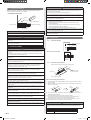
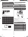
2. 4. Optional parts
Square ange
Model name : UTD–SF045T
(P/N 9098180007)
Round ange
Model name : UTD–RF204
(P/N 9093160004)
40 mm
204 mm
1065 mm
85 mm
ø195 mm
ø205 mm
ø225 mm
ø235 mm
Long-life lter
Model name : UTD–LF25NA
(P/N 9079892004)
507 mm
239 mm
Remote sensor
Model name : UTY-XSZX (P/N 9002763005)
External control wire set
Model name : UTD-ECS5A (P/N 9077359004)
3. GENERAL SPECIFICATION
3. 1. Type of copper pipe and insulation material
CAUTION
Refer to the Installation manual of the outdoor unit for description of the length of
connecting pipe or for difference of its elevation.
Diameter [mm (in.)]
Liquid
6.35 (1/4)
Gas
15.88 (5/8)
• Use pipe with water-resistant heat insulation.
CAUTION
Install heat insulation around both the gas and liquid pipes. Failure to do so may
cause water leaks.
Use heat insulation with heat resistance above 120 °C. (Reverse cycle model only)
In addition, if the humidity level at the installation location of the refrigerant piping is
expected to exceed 70 %, install heat insulation around the refrigerant piping.
If the expected humidity level is 70-80 %, use heat insulation that is 15 mm or thicker
and if the expected humidity exceeds 80 %, use heat insulation that is 20 mm or
thicker.Ifheatinsulationisusedthatisnotasthickasspecied,condensationmay
form on the surface of the insulation.
In addition, use heat insulation with heat conductivity of 0.045 W/(m·K) or less (at 20 °C).
3. 2. Electrical requirement
CAUTION
Beforetheelectricalworking,conrmelectricalstandardsandregulationsineach
country, region, or installing place. Then select appropriate cables and breakers that
comply with them.
Cable Cable size (mm
2
) Type Remarks
Connection cable 1.5 (MIN.) Type 60245 IEC57 3Cable+Earth (Ground),
1φ220-240V
Max. Cable Length: Limit voltage drop to less than 2%. Increase cable gauge if voltage
drop is 2% or more.
4. INSTALLATION WORK
WARNING
Do not turn on the power until all installation work is complete.
Carryingandinstallationoftheunitshouldbeperformedbyasufcientnumberof
peopleandwithsufcientequipmentthatisadequatefortheweightoftheunit.
Performingsuchworkwithaninsufcientnumberofpeopleorwithinadequate
equipment could result in dropping of the unit or personal injury.
CAUTION
For installation details, refer to the technical data.
9381066056-03_IM_EN.indd 2 16/05/2019 13:30:55

En-3
Placetheunitwhereitispossibletoinstallorremovethecontrolbox,fanunitsandlter.
500 mm
300 mm
100 mm
Maintenance hole
Control box
Intake panel
1550 mm
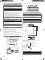
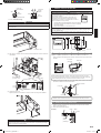
4. 3. Installing the unit
WARNING
Carryingandinstallationoftheunitshouldbeperformedbyasufcientnumber
ofpeopleandwithsufcientequipmentthatisadequatefortheweightoftheunit.
Performingsuchworkwithaninsufcientnumberofpeopleorwithinadequate
equipment could result in dropping of the unit or personal injury.
If the job is done with the panel frame only, there is a risk that the unit will come loose.
Please take care.
When fastening the hangers, make the bolt positions uniform.
CAUTION
Conrmthedirectionsoftheairintakeandoutletbeforeinstallingtheunit.
Hanging bolt installation diagram.
(Example)
(Top side)
(Left side)
740 mm
* 477 mm
AIR
AIR
1135 mm
270 mm
1177 mm
* The distance indicated is adjustable according to the place of the hanging bolts.
(MAX : 550 mm, MIN : 410 mm)
Slide the unit in the direction of the arrow and fasten it.
Hanging bolt M10
(Field supply)
Special nut A (Accessory)
Washer
(Field supply)
Special nut B (Accessory)
Hanger (Accessory)
Bolt Strength 9.81 to 14.71 N·m (100 to 150 kgf·cm)
WARNING
Fasten the unit securely with special nuts A and B so that the unit does not fall.
4. 1. Selecting an installation location
Decide the mounting position together with the customer as follows:
WARNING
Select installation locations that can properly support the weight of the indoor unit
and which will not amplify sound or vibration. If the installation location is not strong
enough, the indoor unit may fall and cause injuries.
Install the units securely so that they do not topple or fall.
CAUTION
Do not install the indoor unit in the following areas:
• Area with high salt content, such as at the seaside.
It will deteriorate metal parts, causing the parts to fall or the unit to leak water.
• Arealledwithmineraloilorcontainingalargeamountofsplashedoilorsteam,
such as a kitchen.
It will deteriorate plastic parts, causing the parts to fall or the unit to leak water.
• Area that generates substances that adversely affect the equipment, such as
sulphuric gas, chlorine gas, acid, or alkali. It will cause the copper pipes and brazed
joints to corrode, which can cause refrigerant leakage.
• Areathatcancausecombustiblegastoleak,containssuspendedcarbonbresor
ammabledust,orvolatileinammablessuchaspaintthinnerorgasoline.Ifgas
leaksandsettlesaroundtheunit,itcancauseare.
• Area where animals may urinate on the unit or ammonia may be generated.
Do not use the unit for special purposes, such as storing food, raising animals, growing
plants, or preserving precision devices or art objects. It can degrade the quality of the
preserved or stored objects.
Do not install where there is the danger of combustible gas leakage.
Donotinstalltheunitnearasourceofheat,steam,orammablegas.
Install the unit where drainage does not cause any trouble.
Install the indoor unit, outdoor unit, power supply cable, transmission cable, and remote
control cable at least 1 m away from a television or radio receivers. The purpose of this
istopreventTVreceptioninterferenceorradionoise.
(Even if they are installed more than 1 m apart, you could still receive noise under
some signal conditions.)
Install the unit where ambient temperature does not reach 60°C or more.
Take a measure such as ventilation for an environment in which heat is retained.
If children under 10 years old may approach the unit, take preventive measures so that
they cannot reach the unit.
(1) Install the indoor unit in a place which can withstand a load of at least 5 times the
weight of the unit.
(2) The inlet and outlet ports should not be obstructed; the air should be able to blow all
over the room.
(3) Leave the space required to service the air conditioner.
(4) Install the unit where connection to the outdoor unit is easy.
(5) Install the unit where the connection pipe can be easily installed.
(6) Install the unit where the drain pipe can be easily installed.
(7) Installtheunitwherenoiseandvibrationsarenotamplied.
(8) Take servicing, etc., into consideration and leave the spaces. Also install the unit where
theltercanberemoved.
(9) Do not install the unit where it will be exposed to direct sunlight.
Correctinitialinstallationlocationisimportantbecauseitisdifculttomoveunitafteritis
installed.
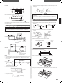
4. 2. Installation dimensions
300 mm
or more
150 mm
or more
2500 mm or more
(When no ceiling)
Floor
Place the unit where it is possible to install or remove the control box.
300 mm
500 mm
500 mm
100 mm
Maintenance hole
Control box
9381066056-03_IM_EN.indd 3 16/05/2019 13:30:56

En-4
Levelling
Base vertical direction levelling on the unit (right and left).
(Left side)
Level
AIR
AIR
Base horizontal direction levelling on top of the unit.
Drain hose
0 – 5 mm
Level
Give a slight tilt to the side to which the drain hose is connected. The tilt should be in the
range of 0 mm to 5 mm.
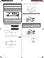
4. 4. Installing the drain hose
CAUTION
Install the drain hose in accordance with the instructions in this installation instruction
sheet and keep the area warm enough to prevent condensation. Problems with the
piping may lead to water leaks.
Installthedrainhoseaccordingtothemeasurementsgiveninthefollowinggure.
(Left side)
240 mm
Gas pipe
Drain pipe
ø 38 mm (O.D.)
Liquid pipe
32 mm
66 mm
114 mm
(Right side)
240 mm
Drain pipe
ø 38 mm (O.D.)
The drain cap is attached
at the factory setting.
32 mm
NOTE:
• Usegeneralhardpolyvinylchloridepipe(VP25)[outsidediameter38mm]andconnect
it with adhesive (polyvinyl chloride) so that there is no leakage.
• Installthedrainhosewithdownwardgradient(1/50to1/100)sotherearenorisesor
traps in the hose.
Drain
hose
Outlet air
ow
Arrange the drain hose
lower than this portion
OK
PROHIBITED
Rise
Trap
• Whenthehoseislong,installsupporters.
Supporter
1.5 to 2 m
• Donotperformairbleeding.
Air bleeding
•
When the unit is shipped from the factory, the drain port is on the left side (control box side).
• Whenusingthedrainportontherightsideoftheunit,reinstallthedraincaptotheleft
side drain port.
Drain port
Drain cap
Cable tie (large) (Accessory)
CAUTION
Always check that the drain cap is installed to the unused drain port and is fastened
with the cable tie.
Ifthedraincapisnotinstalled,orisnotsufcientlyfastenedbythecabletie,water
may drip during the cooling operation.
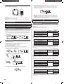
4. 5. Installing the drain hose heat insulation
• Alwaysheatinsulatetheindoorsideofthedrainhose.
(1) Cut the drain hose insulation at a position approximately 80 mm from the end with
cutters, etc.
450 mm
370 mm
170 mm
80 mm
170 mm
80 mm
Cut line
(2) Stick the large drain hose insulation at the drain hose installation side.
Drain hose
insulation
(large)
Unit
Drain hose
Unit
Drain hose
insulation
(large)
Drain hose
0 mm
(3) Stick the small drain hose insulation at the drain cap side.
(4) Cover the drain cap with the drain hose insulation.
Drain hose insulation (small)
Unit
Drain cap
Unit
Drain hose
insulation
(small)
0 mm
4. 6. Intake duct connection
Followtheprocedureinthefollowinggure.
1015 mm
240 mm
Theairintakeductcanbechangedbyreplacingtheintakegrilleandange.
Forthebottomairintake,position(1)theintakegrille,and(2)theange,asshowninthe
followinggure.(Thefactorysettingisbackairintake.)
(2)
(1)
9381066056-03_IM_EN.indd 4 16/05/2019 13:30:57

En-5
CAUTION
When air is taken in from the bottom side, the operating sound of the product will
easily enter the room.
Install the product and intake grilles where the affect of the operating sound is small.
To prevent people from touching the parts inside the unit, be sure to install grilles on
the inlet and outlet ports. The grilles must be designed in such a way that cannot be
removed without tools.
Recommended range of static pressure is 35 Pa to 150 Pa.
If an intake duct is installed, take care not to damage the temperature sensor (the
temperaturesensorisattachedtotheintakeportange).
Be sure to install the air inlet grille and the air outlet grille for air circulation. The
correct temperature cannot be detected.
Unit
(Room)
Air Outlet Grille Air Inlet Grille
When connecting the duct, perform duct-insulation appropriate for the installing
environment.
Inappropriate insulation work may cause condensation on the surface of the insulating
material, and may lead to condensation dripping.
Besuretoinstalltheairlterintheairinlet.Iftheairlterisnotinstalled,theheat
exchanger may be clogged and its performance may decrease.
4. 7. Outlet duct connection
(1) Duct installation pattern ( CUT PART)
• Squareduct
• Roundductoutlet×4
(Factory setting)
When using as a square duct
(1-1) Cut the slit seam
with a cutter.
(1-2) Turn up the insulation around the points to be cut according to the outlet port
shape working points so that the insulation does not stick out at the
part.
Cut Cut
CutCut
(1-3) Cut with nippers and remove the sheet metal.
(2) Since there is a slit in the insulation, use radio pliers, tweezers, etc. to stretch the
screwholepartusedwheninstallingtheroundangeandsquareangewhen
connecting the duct.
4. 8. Fresh air intake
(Processing before use)
(1) When taking in fresh air, cut a slit shaped cabinet in the left side of the outer case with
nippers.
Cut
Cut
Square hole
Cabinet (iron plate)
CAUTION
When removing the cabinet (iron plate), be careful not to damage the indoor unit
internal parts and surrounding area (outer case).
When processing the cabinet (iron plate), be careful not to injure yourself with burrs,
etc.
(2) Installtheroundangetothefreshairintake.
Roundange(Optionalparts)
(3) Connecttheducttotheroundange.
(4) Seal with a band, vinyl tape, etc. so that air does not leak from the connection.
Duct
9381066056-03_IM_EN.indd 5 16/05/2019 13:30:58

En-6
5. PIPE INSTALLATION
WARNING
Duringinstallation,makesurethattherefrigerantpipeisattachedrmlybeforeyou
run the compressor.
Do not operate the compressor under the condition of refrigerant piping not attached
properly with 2-way or 3-way valve open. This may cause abnormal pressure in the
refrigeration cycle that leads to breakage and even injury.
During the pump-down operation, make sure that the compressor is turned off before
you remove the refrigerant piping.
Do not remove the connection pipe while the compressor is in operation with 2-way or
3-way valve open. This may cause abnormal pressure in the refrigeration cycle that
leads to breakage and even injury.
When installing and relocating the air conditioner, do not mix gases other than the
speciedrefrigerant(R410A)toentertherefrigerantcycle.
If air or other gas enters the refrigerant cycle, the pressure inside the cycle will rise to
an abnormally high value and cause breakage, injury, etc.
If refrigerant leaks while work is being carried out, ventilate the area. If the refrigerant
comesincontactwithaame,itproducesatoxicgas.
CAUTION
Be more careful that foreign matter (oil, water, etc.) does not enter the piping than with
refrigerant R410A models. Also, when storing the piping, securely seal the openings
by pinching, taping, etc.
While welding the pipes, be sure to blow dry nitrogen gas through them.
5. 1. Selecting the pipe material
CAUTION
Do not use existing pipes.
Use pipes that have clean external and internal sides without any contamination which
may cause trouble during use, such as sulphur, oxide, dust, cutting waste, oil, or water.
It is necessary to use seamless copper pipes.
Material : Phosphor deoxidized seamless copper pipes
It is desirable that the amount of residual oil is less than 40 mg/10 m.
Do not use copper pipes that have a collapsed, deformed, or discoloured portion
(especially on the interior surface). Otherwise, the expansion valve or capillary tube may
become blocked with contaminants.
Improper pipe selection will degrade performance. As an air conditioner using R410A
incurs pressure higher than when using conventional refrigerant, it is necessary to
choose adequate materials.
•Thicknesses of copper pipes used with R410A are as shown in the table.
•Never use copper pipes thinner than those indicated in the table even if they are available
on the market.
Pipe outside diameter [mm (in.)] Thickness [mm]
6.35 (1/4) 0.8
9.52 (3/8) 0.8
12.70 (1/2) 0.8
15.88 (5/8) 1.0
19.05 (3/4) 1.2
5. 2. Pipe connection
5. 2. 1. Flaring
•UsespecialpipecutterandaretoolexclusiveforR410A.
(1) Cut the connection pipe to the necessary length with a pipe cutter.
(2) Hold the pipe downward so that cuttings will not enter the pipe and remove any burrs.
(3) Insertthearenut(alwaysusethearenutattachedtotheindoorandoutdoorunits
respectively)ontothepipeandperformtheareprocessingwithaaretool.Usethe
specialR410Aaretool,ortheconventionalaretool.Leakageofrefrigerantmay
resultifotherarenutsareused.
(4) Protect the pipes by pinching them or with tape to prevent dust, dirt, or water from
entering the pipes.
Checkif[L]isareduniformly
and is not cracked or scratched.
Pipe
Die
B
A
L
Pipe outside
diameter
[mm (in.)]
Dimension A [mm]
Dimension B
-
0
0.4
[mm]
Flare tool for R410A,
clutch type
6.35 (1/4)
0 to 0.5
9.1
9.52 (3/8) 13.2
12.70 (1/2) 16.6
15.88 (5/8) 19.7
19.05 (3/4) 24.0
WhenusingconventionalaretoolstoareR410Apipes,thedimensionAshouldbe
approximately0.5mmmorethanindicatedinthetable(foraringwithR410Aaretools)to
achievethespeciedaring.UseathicknessgaugetomeasurethedimensionA.
Width across
ats
Pipe outside
diameter [mm (in.)]
Width across ats
of Flare nut [mm]
6.35 (1/4) 17
9.52 (3/8) 22
12.70 (1/2) 26
15.88 (5/8) 29
19.05 (3/4) 36
5. 2. 2. Bending pipes
•If pipes are shaped by hand, be careful not to collapse them.
•Do not bend the pipes in an angle more than 90°.
•Whenpipesarerepeatedlybendorstretched,thematerialwillharden,makingitdifcult
to bend or stretch them any more.
•Do not bend or stretch the pipes more than 3 times.
CAUTION
To prevent breaking of the pipe, avoid sharp bends. Bend the pipe with a radius of
curvature of 150 mm or over.
If the pipe is bent repeatedly at the same place, it will break.
5. 2. 3. Connecting pipes
CAUTION
Be sure to apply the pipe against the port on the indoor unit correctly. If the centring is
improper,thearenutcannotbetightenedsmoothly.Ifthearenutisforcedtoturn,
the threads will be damaged.
Donotremovethearenutfromtheindoorunitpipeuntilimmediatelybefore
connecting the connection pipe.
Donotusemineraloilonaredpart.Preventmineraloilfromgettingintothesystem
as this would reduce the lifetime of the units.
(1) Detach the caps and plugs from the pipes.
(2) Centringthepipeagainstportontheindoorunit,turnthearenutwithyourhand.
Topreventgasleakage,coattheare
surface with alkylbenzene oil (HAB).
Do not use mineral oil.
Whenthearenutistightenedproperlybyyourhand,useatorquewrenchtonally
tighten it.
Holding
spanner
Torque wrench
Unit
side
90°
CAUTION
Hold the torque wrench at its grip, keeping it in the right angle with the pipe, in order to
tightenthearenutcorrectly.
Tightenthearenutswithatorquewrenchusingthespeciedtighteningmethod.
Otherwise,thearenutscouldbreakafteraprolongedperiod,causingrefrigerantto
leakandgenerateahazardousgasiftherefrigerantcomesintocontactwithaame.
Flare nut [mm (in.)] Tightening torque [N·m (kgf·cm)]
6.35 (1/4) dia. 16 to 18 (160 to 180)
9.52 (3/8) dia. 32 to 42 (320 to 420)
12.70 (1/2) dia. 49 to 61 (490 to 610)
15.88 (5/8) dia. 63 to 75 (630 to 750)
19.05 (3/4) dia. 90 to 110 (900 to 1,100)
9381066056-03_IM_EN.indd 6 16/05/2019 13:30:58

En-7
5. 3. Installing heat insulation
Install the heat insulation material after performing a refrigerant leak check (see the
Installation Manual for the outdoor unit for details).
COUPLER HEAT INSULATION
No gaps
Indoor unit side
Be sure to overlap
the insulation.
(Gas and liquid pipes)
Coupler heat insulation
CAUTION
There should be no gaps between the insulation and the product.
CAUTION
After connecting the piping, check the all joints for gas leakage with gas leak detector.
When inspecting gas leakage, always use the vacuum pump for pressure. Do not use
nitrogen gas.
Install heat insulation around both the large (gas) and small (liquid) pipes. Failure to
do so may cause water leaks.
6. ELECTRICAL WIRING
WARNING
Electrical work must be performed in accordance with this Manual by a person
certiedunderthenationalorregionalregulations.Besuretouseadedicatedcircuit
for the unit.
Aninsufcientpowersupplycircuitorimproperlyperformedelectricalworkcancause
seriousaccidentssuchaselectricshockorre.
Before starting work, check that power is not being supplied to the indoor unit and
outdoor unit.
Usetheincludedconnectioncablesandpowercablesoronesspeciedbythe
manufacturer.Improperconnections,insufcientinsulation,orexceedingtheallowable
currentcancauseelectricshockorre.
For wiring, use the prescribed type of cables, connect them securely, making sure
that there are no external forces of the cables applied to the terminal connections.
Improperly connected or secured cables can cause serious accidents such as
overheatingtheterminals,electricshock,orre.
Do not modify the power cables, use extension cables, or use any branches in the
wiring.Improperconnections,insufcientinsulation,orexceedingtheallowable
currentcancauseelectricshockorre.
Match the terminal board numbers and connection cable colours with those of the
outdoor unit. Erroneous wiring may cause burning of the electric parts.
Securely connect the connection cables to the terminal board. In addition, secure the
cables with wiring holders. Improper connections, either in the wiring or at the ends of
thewiring,cancauseamalfunction,electricshock,orre.
Always fasten the outside covering of the connection cable with the cable clamp. (If
the insulator is chafed, electric leakage may occur.)
Securely install the electrical box cover on the unit. An improperly installed electrical
boxcovercancauseseriousaccidentssuchaselectricshockorrethroughexposure
to dust or water.
Install sleeves into any holes made in the walls for wiring. Otherwise, a short circuit
could result.
Install a ground leakage breaker. In addition, install the ground leakage breaker so
that the entire AC main power supply is cut off at the same time. Otherwise, electric
shockorrecouldresult.
Install a ground leakage breaker.
Ifagroundleakagebreakerisnotinstalled,itmaycauseelectricshockorre.
Always connect the earth (ground) cable.
Improper earthing (grounding) work can cause electric shocks.
Install the remote control cables so as not to be direct touched with your hand.
Perform wiring work in accordance with standards so that the air conditioner can be
operated safely and positively.
Connecttheconnectioncablermlytotheterminalboard.Imperfectinstallationmay
causeare.
CAUTION
Ground the unit.
Do not connect the earth (ground) cable to a gas pipe, water pipe, lightning rod, or a
telephone earth (ground) cable.
Improper earthing (grounding) may cause electric shock.
Do not connect power supply cables to the transmission or remote control terminals,
as this will damage the product.
Never bundle the power supply cable and transmission cable together. Bundling these
cables together will cause miss operation.
When handling PCB, static electricity charged in the body may cause malfunction of
the PCB. Follow the cautions below:
• Establish a ground for the indoor and outdoor units and peripheral devices.
• Cut power (breaker) off.
• Touch metal part of the indoor and outdoor units for more than 10 seconds to
discharge static electricity charged in the body.
• Do not touch terminals of parts and patterns implemented on PCB.
Install circuit breakers, which have the terminal spacing of more than 3 mm, in a place
of near the indoor unit and outdoor unit.
Be sure to execute the electrical work according to the Laws of each country and the
Installation Instructions. In addition, be sure to set as exclusive line and use the rated
voltage and circuit breaker.
6. 1. Wiring method
6. 1. 1. Connection diagrams
Connection cable to outdoor unit
Earth (ground) line
Power line
Control line
Wired remote controller cable
Red
White
Black
Indoor
unit side
6. 1. 2. Connection cable preparation
Keep the earth (ground) wire longer than the other wires.
Power supply cable
or connection cable
Earth wire
20 mm
50 mm or more
Use a 4-core wire cable.
How to connect wiring to the terminals.
(1) Useringterminalswithinsulatingsleevesasshowninthegurebelowtoconnectto
the terminal block.
(2) Securely clamp the ring terminals to the wires using an appropriate tool so that the
wires do not come loose.
Strip 10 mm
Ring
terminal
Sleeve
(3) Usethespeciedwires,connectthemsecurely,andfastenthemsothatthereisno
stress placed on the terminals.
(4) Use an appropriate screwdriver to tighten the terminal screws.
Do not use a screwdriver that is too small, otherwise, the screw heads may be
damaged and prevent the screws from being properly tightened.
(5) Do not tighten the terminal screws too much, otherwise, the screws may break.
(6) See the table below for the terminal screw tightening torques.
WARNING
Useringterminalsandtightentheterminalscrewstothespeciedtorques,otherwise,
it may cause abnormal overheating and possibly cause serious damage inside the
unit.
Tightening torque [N·m (kgf·cm)]
M4 screw 1.2 to 1.8 (12 to 18)
M5 screw 2.0 to 3.0 (20 to 30)
9381066056-03_IM_EN.indd 7 16/05/2019 13:30:59

En-8
Screw with
special washer
Ring
terminal
Terminal blocks
Wire
Wire
Screw with
special
washer
Ring
terminal
6. 1. 3. Connection wiring
CAUTION
Be careful not to mistake the power supply cable and connection wires when installing.
Install so that the wires for the remote controller will not come in contact with other
connection wires.
(1)
Remove the control box cover and install each connection wire.
Control box cover
Screw
(2) After wiring is complete, secure the remote controller cable and connection cable with
cable clamps.
45 mm or more
Cable clamp
Cable clamp
Connection cable
(to outdoor unit)
Remote
controller cable
(3) Install control box cover.
Adjust the position of the screws for control box cover according to the installation.
CAUTION
Do not bundle the remote controller cable, or wire the remote controller cable in
parallel, with the indoor unit connection wire (to the outdoor unit) and the power supply
cable. It may cause erroneous operation.
7. REMOTE CONTROLLER SETTING
CAUTION
When detecting the room temperature using the remote
controller, please set up the remote controller according to
the following conditions.
If the remote controller is not well set, the correct room
temperature will not be detected, and thus the abnormal
conditions like “not cooled” or “not heated” will occur even if
the air conditioner is running normally.
Temperature sensor
• A location with an average temperature for the room being air-conditioned.
• Not directly exposed to the outlet air from the air conditioner.
• Out of direct sunlight.
• Awayfromtheinuenceofotherheatsources.
When installing the remote controller and cable near a source of electromagnetic
waves, separate the remote controller from the source of the electromagnetic waves
and use shielded cable.
Do not touch the remote controller PC board and PC board parts directly with your
hands.
Hole
Hole 2
Hole 3
Unit : mm
33.5
4.5
4.5
4.5
12.5
45.3
63.5
83.5
15.3
30
23
8
6
17120
120
7. 1. Installing the remote controller
(1) Open the operation panel on the front of the remote controller, remove the two
screwsindicatedinthefollowinggure,andthenremovethefrontcaseoftheremote
controller.
Connector
Front case
(back side)
Rear case
Screws
When installing the remote controller, remove the connector from the front case.
The wires may break if the connector is not removed and the front case hangs down.
When installing the front case, connect the connector to the front case.
(2) Install the rear case to the wall, etc. with the two tapping screws. Refer to the following
information to install the remote controller wires.
Rear case
Connector
Front case
Remote controller
wires
Install the remote controller wires so as not to be directly touched with your hand.
7. 2. Routing the remote controller wires
(1) Install the remote controller wires to the terminals on the top of the rear case as
showninthefollowinggure.
(2) Fasten the wires with the cable tie.
(Example)
Cable tie
(small)
(Accessory)
1. Red
2. White
3. Black
9381066056-03_IM_EN.indd 8 16/05/2019 13:31:00

En-9
7. 3. Setting the DIP switches
When using a battery (memory backup)
1
2
3
4
5
6
Front case (back side)
OFF ON
ON
DIP switch1
Change the DIP switch setting to use batteries. (The DIP switch is not set to use batteries
at the factory.)
Change DIP switch No. 6 from OFF to ON.
If batteries are not used, all of the settings stored in memory will be deleted if there is a
power failure.
8. FUNCTION SETTING
CAUTION
Conrmwhetherthewiringworkforoutdoorunithasbeennished.
Conrmwhetherthecoverforelectriccontrolboxontheoutdoorunitisclose.
8. 1. Turning on the power
(1) Check the remote controller wiring and DIP switch settings.
(2) Install the front case. When installing the front case, connect the connector to the front
case.
(3) Check the indoor and outdoor unit wiring and circuit board switch settings, and then
turnontheindoorandoutdoorunits.After“9C”hasashedonthesettemperature
display for several seconds, the clock display will appear in the centre of the remote
controller display.
The clock display will appear in the centre of the remote controller display.
SU
MO
TU
WE
TH FR
SA
8. 2. Setting method
•This procedure changes to the function settings used to control the indoor unit according
to the installation conditions.
•Incorrect settings can cause the indoor unit malfunction.
•After the power is turned on, perform the “FUNCTION SETTING” according to the
installation conditions using the remote controller.
•The settings may be selected between the following two:
•FunctionNumberorSettingValue.
•Settings will not be changed if invalid numbers or setting values are selected.
(1) Press the SET TEMP. buttons (
) ( ) and FAN button simultaneously for more than
5 seconds to enter the function setting mode.
SU
MO
TU
WE
TH FR
SA
Press the SET BACK button to select the indoor R.C. address.
SET BACK
SU
MO
TU
WE
TH FR
SA
R.C. address of INDOOR UNIT
(2) Press the Set time buttons (
) ( ) to select the function number.
SU
MO
TU
WE
TH FR
SA
Function number
(3) Press the SET TEMP. buttons (
) ( ) to select the setting value.
Thedisplayashesasshowntotherightduringsettingvalueselection.
(4) PresstheTIMERSETbuttontoconrmthesetting.PresstheTIMERSETbuttonfora
fewsecondsuntilthesettingvaluestopsashing.
Ifthesettingvaluedisplaychangesorif“--”isdisplayedwhentheashingstops,
the setting value has not been set correctly. (An invalid setting value may have been
selected for the indoor unit.)
SU
MO
TU
WE
TH FR
SA
Setting value
(5) Repeat steps 2 to 4 to perform additional settings. Press the SET TEMP. buttons
(
) ( ) and FAN button simultaneously again for more than 5 seconds to cancel
the function setting mode. In addition, the function setting mode will be automatically
cancelled after 1 minute if no operation is performed.
(6) After completing the FUNCTION SETTING, be sure to turn off the power and turn it on again.
CAUTION
After turning off the power, wait 30 seconds or more before turning on it again. The
FUNCTION SETTING doesn’t become effective if it doesn’t do so.
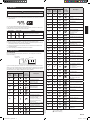
8. 3. Function setting
The function settings are as follows.
Filter Sign
•Selectappropriateintervalsfordisplayingtheltersignontheindoorunitaccordingtothe
estimated amount of dust in the air of the room.
If the indication is not required, select “No indication” (03).
(
♦
...Factory setting)
Setting Description
Function
Number
Setting
Value
Standard (2500 hours)
11
00
Long interval (4400 hours) 01
Short interval (1250 hours) 02
♦
No indication 03
Static pressure
•Select appropriate static pressure according to the installation conditions.
(
♦
...Factory setting)
Setting Description
Function
Number
Setting
Value
♦
Normal (35 Pa)
21
00
High static pressure 1 (60 Pa) 01
High static pressure 2 (95 Pa) 02
High static pressure 3 (150 Pa) 03
Room temperature control for cooling
•Depending on the installed environment, correction of the room temperature sensor may
be required.
•Select the appropriate control setting according to the installed environment.
(
♦
...Factory setting)
Setting Description
Function
Number
Setting
Value
♦
Standard
30
00
Lower control 01
Slightly higher control 02
Higher control 03
Room temperature control for heating
•Depending on the installed environment, correction of the room temperature sensor may
be required.
•Select the appropriate control setting according to the installed environment.
(
♦
...Factory setting)
Setting Description
Function
Number
Setting
Value
♦
Standard
31
00
Lower control 01
Slightly lower control 02
Higher control 03
Auto Restart
•Enable or disable automatic restart after a power interruption.
(
♦
...Factory setting)
Setting Description
Function
Number
Setting
Value
♦
Enable
40
00
Disable 01
* Auto restart is an emergency function such as for power outage etc. Do not attempt to
use this function in normal operation. Be sure to operate the unit by remote controller or
external device.
9381066056-03_IM_EN.indd 9 16/05/2019 13:31:00

En-10
Room temperature sensor switching
(Only for wired remote controller)
When using the Wired remote controller temperature sensor, change the setting to “Both”
(01).
(
♦
...Factory setting)
Setting Description
Function
Number
Setting
Value
♦
Indoor Unit
42
00
Both 01
00: Sensor on the indoor unit is active.
01: Sensors on both indoor unit and wired remote controller are active.
Cold Air Prevention
•This setting is to disable the cold air prevention function during heating operation. When
disabled, the fan setting will always follow the setting on the remote controller. (Excluding
defrost mode)
(
♦
...Factory setting)
Setting Description
Function
Number
Setting
Value
♦
Enable
43
00
Disable 01
External input control
•“Operation/Stop” mode or “Forced stop” mode can be selected.
(
♦
...Factory setting)
Setting Description
Function
Number
Setting
Value
♦
Operation/Stop mode
46
00
(Setting prohibited) 01
Forced stop mode 02
Room temperature sensor switching (Aux.)
•To use the temperature sensor on the wired remote controller only, change the setting to
“Wired remote controller” (01). This function will only work if the function setting 42 is set
at “Both” (00)
(
♦
...Factory setting)
Setting Description
Function
Number
Setting
Value
♦
Both
48
00
Wired remote controller 01
Setting record
Record any changes to the settings in the following table.
Function setting Setting Value
Filter Sign
Static Pressure
Room temperature control for cooling
Room temperature control for heating
Auto restart
Room temperature sensor switching
Cold air prevention
External input control
Room Temperature Sensor Switching (Aux.)
•After completing the FUNCTION SETTING, be sure to turn off the power and turn it on
again.
8. 4. Setting the room temperature detection location
The detection location of the room temperature can be selected from the following three
examples. Choose the detection location that is best for the installation location.
A. Indoor unit setting (factory setting)
The room temperature is detected by the indoor unit temperature sensor.
(1) WhentheTHERMOSENSORbuttonispressed,thelockdisplayashesbecausethe
function is locked at the factory.
A
Indoor unit
B. Remote controller setting
The room temperature is detected by the remote controller temperature sensor.
(1) Enable the room temperature sensor selection by changing the room temperature
sensor switching in “8.3. Function setting” to “Both”.
(2) Press the THERMO SENSOR button for 5 seconds or more to select the temperature
sensor of the indoor unit or the remote controller.
B
Indoor unit
CAUTION
When selecting the “Remote controller setting”, if the detected
temperature value between the temperature sensor of the indoor unit
and the temperature sensor of the remote controller varies
signicantly,itislikelytoreturntothecontrolstatusoftemperature
sensor of the indoor unit temporarily.
As the temperature sensor of remote controller detects the temperature near the wall,
when there is a certain difference between the room temperature and the wall tempera-
ture, the sensor will not detect the room temperature correctly sometimes.
Especially when the outer side of the wall on which the sensor is positioned is
exposed to the open air, it is recommended to use the temperature sensor of the indoor
unit to detect the room temperature when the indoor and outdoor temperature difference
issignicant.
The temperature sensor of the remote controller is not only used when there is a problem
in the detection of the temperature sensor of the indoor unit.
NOTE:
If the function to change the temperature sensor is used as shown in example A, be sure to
lock the detection location. If the function is locked, the lock display
willashwhen
the THERMO SENSOR button is pressed.
8. 5. Jumper wire setting
Change the following settings by using the jumpers.
This setting is made by cutting the jumper wires on the circuit board of the indoor unit.
JM3
JM2
JM1
Jumper wires
Jumper wire
JM state
Details
Connect
Disconnect
JM1
-
Cannot be used
(Do not change)
JM2
JM3 Disable Enable Fan delay setting
9381066056-03_IM_EN.indd 10 16/05/2019 13:31:01

En-11
9. SPECIAL INSTALLATION METHODS
CAUTION
Be sure to turn off the electrical breaker before making settings.
When setting the DIP switches, do not touch any other parts on the circuit board
directly with your bare hands.
9. 1. Group control system
CAUTION
Group control is only possible between units with remote controllers of the same type.
Toconrmthetypeofremotecontroller,seethebackoftheremotecontrolleror“2.3.
Accessories”.
A number of indoor units can be operated at the same time using a single remote controller.
(1) Wiring method (indoor unit to remote controller)
Indoor
unit
1
Bus wire
Remote
controller cable
Remote controller
When ground wire is necessary
Indoor
unit 2
Indoor
unit
3
Indoor
unit 4
(2) DIP switch setting (Indoor unit)
Set the unit number of each indoor unit using the DIP switches on the indoor unit
circuitboard.(Seethefollowingtableandgure.)
The DIP switches are normally set to make the unit number 00.
Indoor unit Unit number DIP SWITCH No.
1 2 3 4
1
00 OFF OFF OFF OFF
2
01 ON OFF OFF OFF
3
02 OFF ON OFF OFF
4
03 ON ON OFF OFF
5
04 OFF OFF ON OFF
6
05 ON OFF ON OFF
7
06 OFF ON ON OFF
8
07 ON ON ON OFF
9
08 OFF OFF OFF ON
0
09 ON OFF OFF ON
A
10 OFF ON OFF ON
B
11 ON ON OFF ON
C
12 OFF OFF ON ON
D
13 ON OFF ON ON
E
14 OFF ON ON ON
F
15 ON ON ON ON
ON
Example :
Unit number 02
DIP switches
Circuit board in the control box of indoor unit.
NOTE:
Be sure to set the unit numbers sequentially.
• When different indoor unit models are connected using the group control system, some
functions may no longer be available.
•It should not be connected to any other Gr that is not of the same series.
9. 2. Fan delay setting
This setting can be used when the auxiliary heater is mounted.
When the operation is stopped when the indoor unit is operating with an auxiliary heater,
the operation continues 1 minutes.
Refer to “8.5. Jumper wire setting” to change the settings.
10. OPTIONAL PARTS
WARNING
Regulation of cable differs from each locality, refer in accordance with local rules.
This air conditioner can be connected with the following optional kits.
Option type Connector No.
UTY-XSZX (Remote sensor unit) CN8
UTD-ECS5A (External input) CN102
UTD-ECS5A (External output) CN103
CN103
CN102
CN8
Remote sensor
•Remove the existing connector and replace it with the remote sensor connector (ensure
that the correct connector is used).
•The original connector should be insulated to ensure that it does not come into contact
with other electrical circuitry.
Setting for room temperature correction
When a remote sensor is connected, set the function setting of indoor unit as indicated
below.
•Set Function Number “30” (Room temperature control for cooling) to “01”
•Set Function Number “31” (Room temperature control for heating) to “01”
11. CHECK LIST
Pay special attention to the check items below when installing the indoor unit(s). After
installation is complete, be sure to check the following check items again.
Check items Check box
Has the indoor unit been installed correctly?
Has there been a check for gas leaks (refrigerant pipes)?
Has heat insulation work been completed?
Does water drain easily from the indoor units?
Is the voltage of the power source the same as that indicated on the
label on the indoor unit?
Are the wires and pipes all connected completely?
Is the indoor unit grounded?
Istheconnectioncablethespeciedthickness?
Are the inlets and outlets free of any obstacles?
After installation is completed, has the proper operation and handling
been explained to the user?
Operate the unit according to the operating manual provided, and
check that it is operating normally.
9381066056-03_IM_EN.indd 11 16/05/2019 13:31:02

En-12
12. TEST RUN
CAUTION
Supply power to the crankcase heater for at least 12 hours before the start of
operation in winter.
(1) Stop the air conditioner operation.
(2) Press the MODE button and the FAN button simultaneously for 2 seconds or more to
start the test run.
Test run display
(3) Press the START/STOP button to stop the test run.
If “C0” appears in the unit number display, there is a remote controller error. Refer to the
installation manual included with the remote controller.
Unit number Error code Content
Incompatible indoor unit is connected
Indoor unit
↔
remote controller communication
error
13. CUSTOMER GUIDANCE
Explain the following to the customer in accordance with the operating manual:
(1) Starting and stopping method, operation switching, temperature adjustment, timer, air
owswitching,andotherremotecontrolleroperations.
(2) Cleaningandmaintenanceoftheproduct,andotheritemssuchasairltersandair
louvers if applicable.
(3) Give the operating and installation manuals to the customer.
14. ERROR CODES
[SELF-DIAGNOSIS]
If an error occurs, the following display will be shown. (“Er” will appear in the set room
temperature display.)
Unit number
of indoor unit
Error code
EX. Self-diagnosis
If you use a wired type remote controller, error codes will appear on the remote controller
display. If you use a wireless remote controller, the lamps on the IR receiver unit will output
error codes by way of blinking patterns. See the lamp blinking patterns and error codes in
the table below. An error display is displayed only during operation.
Error display
Wired
remote
controller
Error code
Description
OPERATION
lamp
(green)
TIMER
lamp
(orange)
ECONOMY
lamp
(green)
(1)
(1)
Serial communication error
(1)
(2)
Wired remote controller
communication error
(1)
(5)
Checkrununnished
(2)
(1)
Unit number or Refrigerant circuit
address setting error
[SimultaneousMulti]
(2)
(2)
Indoor unit capacity error
(2)
(3)
Combination error
(2)
(4)
•Connection unit number
error (indoor secondary unit)
[SimultaneousMulti]
•Connection unit number error
(indoor unit or branch unit)
[FlexibleMulti]
(2)
(7)
Primary unit, secondary unit setup
error[SimultaneousMulti]
(3)
(1)
Power supply interruption error
(3)
(2)
Indoor unit PCB model
information error
(3)
(5)
Manual auto switch error
Error display
Wired
remote
controller
Error code
Description
OPERATION
lamp
(green)
TIMER
lamp
(orange)
ECONOMY
lamp
(green)
(4)
(1)
Room temp. sensor error
(4)
(2)
Indoor unit Heat Ex. Middle temp.
sensor error
(5)
(1)
Indoor unit fan motor error
(5)
(3)
Drain pump error
(5)
(7)
Damper error
(5)
(15)
Indoor unit error
(6)
(2)
Outdoor unit main PCB
model information error or
communication error
(6)
(3)
Inverter error
(6)
(4)
Activeltererror,PFCcircuiterror
(6)
(5)
Trip terminal L error
(6)
(10)
Display PCB microcomputers
communication error
(7)
(1)
Discharge temp. sensor error
(7)
(2)
Compressor temp. sensor error
(7)
(3)
Outdoor unit Heat Ex. liquid temp.
sensor error
(7)
(4)
Outdoor temp. sensor error
(7)
(5)
Suction Gas temp. sensor error
(7)
(6)
•2-way valve temp. sensor error
•3-way valve temp. sensor error
(7)
(7)
Heat sink temp. sensor error
(8)
(2)
•Sub-cool Heat Ex. gas inlet
temp. sensor error
•Sub-cool Heat Ex. gas outlet
temp. sensor error
(8)
(3)
Liquid pipe temp. sensor error
(8)
(4)
Current sensor error
(8)
(6)
•Discharge pressure sensor error
•Suction pressure sensor error
•High pressure switch error
(9)
(4)
Trip detection
(9)
(5)
Compressor rotor position
detection error (permanent stop)
(9)
(7)
Outdoor unit fan motor 1 error
(9)
(8)
Outdoor unit fan motor 2 error
(9)
(9)
4-way valve error
(9)
(10)
Coil (expansion valve) error
(10)
(1)
Discharge temp. error
(10)
(3)
Compressor temp. error
(10)
(4)
High pressure error
(10)
(5)
Low pressure error
(13)
(2)
Branch boxes error
[FlexibleMulti]
Display mode
: 0.5s ON / 0.5s OFF
: 0.1s ON / 0.1s OFF
() :Numberofashing
9381066056-03_IM_EN.indd 12 16/05/2019 13:31:06
-
 1
1
-
 2
2
-
 3
3
-
 4
4
-
 5
5
-
 6
6
-
 7
7
-
 8
8
-
 9
9
-
 10
10
-
 11
11
-
 12
12
-
 13
13


Fujitsu ARGA25FMTA-K Installation guide
- Type
- Installation guide
- This manual is also suitable for
Ask a question and I''ll find the answer in the document
Finding information in a document is now easier with AI
Related papers
-
Fujitsu RDA60UHTC-S Installation guide
-
Fujitsu ASGA18FUTA-U Installation guide
-
-
Fujitsu ARSA40UMTB Installation guide
-
Fujitsu UTY-RNBLU Installation guide
-
-
-
-
-
Fujitsu ASGA30FUTC-M Installation guide
Other documents
-
MD Building Products 50148 Installation guide
-
Dimplex DCES09WIFI User manual
-
Tripp Lite Toolless Cat6a Keystone Jack Owner's manual
-
LG AP-W50GT3E0 Installation guide
-
Friedrich C24YJ Ductless Split System Warranty
-
Carrier 38EYV025M Installation guide
-
Acson 5SLY20 Installation guide
-
LG PTVK420 Installation guide