
OPER ATOR'S MANUAL
DITCH BANK
ROTARY CUTTER
MAN1248
(Rev. 7/18/2019)
DBH5.31
DBH5.31Q
DBH6.31
DBH6.31Q

2 Introduction
Gen’l (Rev. 2/25/2016)
TO THE DEALER:
Assembly and proper installation of this product is the responsibility of the Woods
®
dealer. Read manual instructions
and safety rules. Make sure all items on the Dealer’s Pre-Delivery and Delivery Check Lists in the Operator’s Manual
are completed before releasing equipment to the owner.
The dealer must complete the online Product Registration form at the Woods Dealer Website which certifies that
all Dealer Check List items have been completed. Dealers can register all Woods product at
dealer.WoodsEquipment.com under Product Registration.
Failure to register the product does not diminish customer’s warranty rights.
TO THE OWNER:
Read this manual before operating your Woods equipment. The information presented will prepare you to do a better and
safer job. Keep this manual handy for ready reference. Require all operators to read this manual carefully and become
acquainted with all adjustment and operating procedures before attempting to operate. Replacement manuals can be
obtained from your dealer. To locate your nearest dealer, check the Dealer Locator at www.WoodsEquipment.com, or in
the United States and Canada call 1-800-319-6637.
The equipment you have purchased has been carefully engineered and manufactured to provide dependable and
satisfactory use. Like all mechanical products, it will require cleaning and upkeep. Lubricate the unit as specified.
Observe all safety information in this manual and safety decals on the equipment.
For service, your authorized Woods dealer has trained mechanics, genuine Woods service parts, and the necessary
tools and equipment to handle all your needs.
Use only genuine Woods service parts. Substitute parts will void the warranty and may not meet standards required for
safe and satisfactory operation. Record the model number and serial number of your equipment in the spaces
provided:
Model: _______________________________ Date of Purchase: _____________________
Serial Number: (see Safety Decal section for location) ____________________________________
Provide this information to your dealer to obtain correct repair parts.
Throughout this manual, the term NOTICE is used to indicate that failure to observe can cause damage to equipment.
The terms CAUTION, WARNING, and DANGER are used in conjunction with the Safety-Alert Symbol (a triangle with
an exclamation mark) to indicate the degree of hazard for items of personal safety.

Introduction 3
MAN1248 (2/26/2018)
TABLE OF CONTENTS
INTRODUCTION . . . . . . . . . . . . . . . . . . . . . . . . . . . . . . . . . . . . . . . . . . . . . . . . . . . . . . . . . . . . . . . . . . . . . 2
SPECIFICATIONS . . . . . . . . . . . . . . . . . . . . . . . . . . . . . . . . . . . . . . . . . . . . . . . . . . . . . . . . . . . . 4
GENERAL INFORMATION. . . . . . . . . . . . . . . . . . . . . . . . . . . . . . . . . . . . . . . . . . . . . . . . . . . . . . 4
ONLINE SAFETY VIDEO . . . . . . . . . . . . . . . . . . . . . . . . . . . . . . . . . . . . . . . . . . . . . . . . . . . . . . . 5
SAFETY . . . . . . . . . . . . . . . . . . . . . . . . . . . . . . . . . . . . . . . . . . . . . . . . . . . . . . . . . . . . . . . . . . . . . . . . . . . . 7
SAFETY RULES. . . . . . . . . . . . . . . . . . . . . . . . . . . . . . . . . . . . . . . . . . . . . . . . . . . . . . . . . . . . . . 7
INSTALLATION . . . . . . . . . . . . . . . . . . . . . . . . . . . . . . . . . . . . . . . . . . . . . . . . . . 7
TRAINING . . . . . . . . . . . . . . . . . . . . . . . . . . . . . . . . . . . . . . . . . . . . . . . . . . . . . . 7
PREPARATION . . . . . . . . . . . . . . . . . . . . . . . . . . . . . . . . . . . . . . . . . . . . . . . . . . 7
TRANSPORTATION. . . . . . . . . . . . . . . . . . . . . . . . . . . . . . . . . . . . . . . . . . . . . . . 8
OPERATION. . . . . . . . . . . . . . . . . . . . . . . . . . . . . . . . . . . . . . . . . . . . . . . . . . . . . 8
MAINTENANCE . . . . . . . . . . . . . . . . . . . . . . . . . . . . . . . . . . . . . . . . . . . . . . . . . . 9
STORAGE . . . . . . . . . . . . . . . . . . . . . . . . . . . . . . . . . . . . . . . . . . . . . . . . . . . . . . 9
SAFETY & INSTRUCTIONAL DECALS . . . . . . . . . . . . . . . . . . . . . . . . . . . . . . . . . . . . . . . . . . . 10
OPERATION. . . . . . . . . . . . . . . . . . . . . . . . . . . . . . . . . . . . . . . . . . . . . . . . . . . . . . . . . . . . . . . . . . . . . . . . 13
OPERATION. . . . . . . . . . . . . . . . . . . . . . . . . . . . . . . . . . . . . . . . . . . . . . . . . . . . . . . . . . . . . . . . 13
GENERAL TRACTOR REQUIREMENTS . . . . . . . . . . . . . . . . . . . . . . . . . . . . . 13
TRACTOR FRONT END STABILITY . . . . . . . . . . . . . . . . . . . . . . . . . . . . . . . . . 13
CONNECT CUTTER TO TRACTOR . . . . . . . . . . . . . . . . . . . . . . . . . . . . . . . . . 14
CUTTING HEIGHT ADJUSTMENT . . . . . . . . . . . . . . . . . . . . . . . . . . . . . . . . . . 14
PRE-OPERATION CHECKLIST. . . . . . . . . . . . . . . . . . . . . . . . . . . . . . . . . . . . . 15
GENERAL MOWING . . . . . . . . . . . . . . . . . . . . . . . . . . . . . . . . . . . . . . . . . . . . . 15
TRANSPORT . . . . . . . . . . . . . . . . . . . . . . . . . . . . . . . . . . . . . . . . . . . . . . . . . . . 17
STORAGE . . . . . . . . . . . . . . . . . . . . . . . . . . . . . . . . . . . . . . . . . . . . . . . . . . . . . 17
OWNER SERVICE . . . . . . . . . . . . . . . . . . . . . . . . . . . . . . . . . . . . . . . . . . . . . . . . . . . . . . . . . . . . . . . . . . . 18
OWNER SERVICE . . . . . . . . . . . . . . . . . . . . . . . . . . . . . . . . . . . . . . . . . . . . . . . . . . . . . . . . . . . 18
LUBRICATION . . . . . . . . . . . . . . . . . . . . . . . . . . . . . . . . . . . . . . . . . . . . . . . . . . 18
BLADE SERVICING. . . . . . . . . . . . . . . . . . . . . . . . . . . . . . . . . . . . . . . . . . . . . . 19
CHAIN SHIELDING REPAIR . . . . . . . . . . . . . . . . . . . . . . . . . . . . . . . . . . . . . . . 20
OIL FILTER SERVICE . . . . . . . . . . . . . . . . . . . . . . . . . . . . . . . . . . . . . . . . . . . . 20
SCREEN FILTER SERVICE. . . . . . . . . . . . . . . . . . . . . . . . . . . . . . . . . . . . . . . . 20
FLEXIBLE COUPLER DISK REPLACEMENT. . . . . . . . . . . . . . . . . . . . . . . . . . 21
CLEANING . . . . . . . . . . . . . . . . . . . . . . . . . . . . . . . . . . . . . . . . . . . . . . . . . . . . . 21
TROUBLESHOOTING . . . . . . . . . . . . . . . . . . . . . . . . . . . . . . . . . . . . . . . . . . . . 22
DEALER SERVICE . . . . . . . . . . . . . . . . . . . . . . . . . . . . . . . . . . . . . . . . . . . . . . . . . . . . . . . . . . . . . . . . . . 26
DEALER SERVICE. . . . . . . . . . . . . . . . . . . . . . . . . . . . . . . . . . . . . . . . . . . . . . . . . . . . . . . . . . . 26
GEARBOX MAINTENANCE . . . . . . . . . . . . . . . . . . . . . . . . . . . . . . . . . . . . . . . 26
SEAL REPLACEMENT . . . . . . . . . . . . . . . . . . . . . . . . . . . . . . . . . . . . . . . . . . . 26
SEAL INSTALLATION . . . . . . . . . . . . . . . . . . . . . . . . . . . . . . . . . . . . . . . . . . . . 26
GEARBOX REMOVAL . . . . . . . . . . . . . . . . . . . . . . . . . . . . . . . . . . . . . . . . . . . . 27
GEARBOX INSTALLATION . . . . . . . . . . . . . . . . . . . . . . . . . . . . . . . . . . . . . . . . 27
PUMP MAINTENANCE . . . . . . . . . . . . . . . . . . . . . . . . . . . . . . . . . . . . . . . . . . . 27
MOTOR MAINTENANCE. . . . . . . . . . . . . . . . . . . . . . . . . . . . . . . . . . . . . . . . . . 28
PUMP & MOTOR SEAL AND GEAR REPLACEMENT . . . . . . . . . . . . . . . . . . . 29
SPINDLE FLANGE MAINTENANCE . . . . . . . . . . . . . . . . . . .
. . . . . . . . . . . . . . 30
BLADE ROTATION CHANGE . . . . . . . . . . . . . . . . . . . . . . . . . . . . . . . . . . . . . . 31
CROSSBAR . . . . . . . . . . . . . . . . . . . . . . . . . . . . . . . . . . . . . . . . . . . . . . . . . . . . 32
UNIVERSAL JOINT REPAIR . . . . . . . . . . . . . . . . . . . . . . . . . . . . . . . . . . . . . . . 33
DEALER CHECK LISTS . . . . . . . . . . . . . . . . . . . . . . . . . . . . . . . . . . . . . . . . . . . . . . . . . . . . . . . . . . . . . . 35
ASSEMBLY INSTRUCTIONS . . . . . . . . . . . . . . . . . . . . . . . . . . . . . . . . . . . . . . . . . . . . . . . . . . . . . . . . . . 36
ASSEMBLY INSTRUCTIONS. . . . . . . . . . . . . . . . . . . . . . . . . . . . . . . . . . . . . . . . . . . . . . . . . . . 36
DEALER SET UP INSTRUCTIONS . . . . . . . . . . . . . . . . . . . . . . . . . . . . . . . . . . 36
PARTS INDEX . . . . . . . . . . . . . . . . . . . . . . . . . . . . . . . . . . . . . . . . . . . . . . . . . . . . . . . . . . . . . . . . . . . . . . 43
APPENDIX . . . . . . . . . . . . . . . . . . . . . . . . . . . . . . . . . . . . . . . . . . . . . . . . . . . . . . . . . . . . . . . . . . . . . . . . . 57
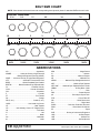
BOLT TORQUE CHART . . . . . . . . . . . . . . . . . . . . . . . . . . . . . . . . . . . . . . . . . . . . . . . . . . . . . . . 57
BOLT SIZE CHART & ABBREVIATIONS . . . . . . . . . . . . . . . . . . . . . . . . . . . . . . . . . . . . . . . . . . 58
INDEX . . . . . . . . . . . . . . . . . . . . . . . . . . . . . . . . . . . . . . . . . . . . . . . . . . . . . . . . . . . . . . . . . . . . . . . . . . . . . 59
REPLACEMENT PARTS WARRANTY . . . . . . . . . . . . . . . . . . . . . . . . . . . . . . . . . . . . . . . . . . . . . . . . . . . 61
PRODUCT WARRANTY . . . . . . . . . . . . . . . . . . . . . . . . . . . . . . . . . . . . . . . . . . . . . . . . . . . . . . . . . . . . . . 62
Si no lee Ingles, pida ayuda a
alguien que si lo lee para que le
traduzca las medidas de seguridad.
LEA EL INSTRUCTIVO!
!

4 Introduction
MAN1248 (2/26/2018)
SPECIFICATIONS
GENERAL INFORMATION
Some illustrations in this manual show the cut-
ter with safety shields removed to provide a better
view. The cutter should never be operated with any
safety shielding removed.
The purpose of this manual is to assist you in operating
and maintaining your cutter. Read it carefully. It fur-
nishes information and instructions that will help you
achieve years of dependable performance. These
instructions have been compiled from extensive field
experience and engineering data. Some information
may be general in nature due to unknown and varying
operating conditions. However, through experience
and these instructions, you should be able to develop
procedures suitable to your particular situation.
The illustrations and data used in this manual were cur-
rent at the time of printing, but due to possible inline
production changes, your machine may vary slightly in
detail. We reserve the right to redesign and change the
machines as may be necessary without notification.
Throughout this manual, references are made to right
and left directions. These are determined by standing
behind the equipment facing the direction of forward
travel. Blade rotation is counterclockwise as viewed
from the top of the cutter.
DBH5.31
DBH5.31Q DBH6.31 DBH6.31Q
Cutting Width 60" 60" 72" 72"
PTO Speed (rpm) 540 1000 540 1000
Blade Tip Speed (feet per minute) 15,800 16,000 18,900 17,700
Minimum Tractor Weight Recommended 4000 lbs 4000 lbs 5000 lbs 5000 lbs
Minimum Tractor HP Recommended 55 HP 55 HP 60 HP 60 HP
Minimum 3-Point Lift Capacity 2500 lbs 2500 lbs 3000 lbs 3000 lbs
Weight (Approximate)
Including Hydraulic Oil and Counter Weights
2250 lbs. 2450 lbs.
Cutting Height (Depending on 3-point hitch height) . . . . . . . . . . . . . . . . . . . . . . . . . . . . . . . . . . . . . . . . 2" - 10"
3-Point Hitch . . . . . . . . . . . . . . . . . . . . . . . . . . . . . . . . . . . . . . . . . . . . . . . . . . . . . . . . . . . . . . . . Category 2 & 3
Offset from Centerline Tractor PTO to Inside Edge of Cut (Approximate) . . . . . . . . . . . . . . . . . . . . . . . . . . . 65"
Transport Width from Centerline PTO to Right Side with Head Raised (Approximate) . . . . . . . . . . . . . . . . . 73"
Transport Width from Centerline PTO to Left Side with Head Raised (Approximate) . . . . . . . . . . . . . . . . . . 51"
Blade Rotation . . . . . . . . . . . . . . . . . . . . . . . . . . . . . . . . . . . . . . . . . . . . . . . . . . . . . . . . . . . . . . . . . . . . . . CCW
(With Option to Convert To CW)
WARNING

Safety 5
Safety Video Online Form (Rev. 1/09/2018)
Watch a Mower Safety Video Online
The AEM (Association of Equipment Manufacturers) offers a safety
training video, Industrial and Agricultural Mower Safety Practices. The
22-minute video can be viewed online for free at TheAEMStore,
https://youtu.be/uEWXsDqhDq0
It reinforces the proper procedures to follow while operating your mowing
equipment. The video does not replace the information contained in the
Operator’s Manual, so please review this manual thoroughly before
operating your new mowing equipment.
Safety Training
Does Make a Difference.
BE SAFE!
BE ALERT!
BE ALIVE!
BE TRAINED
Before Operating Mowers!
ASSOCIATION OF
EQUIPMENT
MANUFACTURERS
Safety Video Order Form

6 Safety
Safety Video Online Form (Rev. 1/09/2018)
Also, available from the Association of Equipment Manufacturers:
A large variety of training materials (ideal for groups) are available for a nominal
charge from AEM. Following is a partial list:
● Training Package for Rotary Mowers/Cutters-English
Contains: DVD & VHS (English)
Guidebook for Rotary Mowers/Cutters (English)
AEM Industrial/Agricultural Mower Safety Manual (English)
AEM Agricultural Tractor Safety Manual (English)
● Training Package for Rotary Mowers/Cutters-English/Spanish
Contains: DVD & VHS (English/Spanish)
Guidebook for Rotary Mowers/Cutters (English/Spanish)
AEM Industrial/Agricultural Mower Safety Manual (English/Spanish)
AEM Agricultural Tractor Safety Manual (English/Spanish)
AEM training packages are available through:
AEM at: www.aem.org
or
Universal Lithographers, Inc.
Email: [email protected]
800-369-2310 tel
866-541-1668 fax

Safety 7
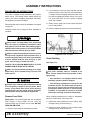
DBH Safety Rules (10/4/2016)
INSTALLATION
Hydraulics must be connected as instructed in
this manual. Do not substitute parts, modify, or
connect in any other way.
TRAINING
Safety instructions are important! Read all
attachment and power unit manuals; follow all
safety rules and safety decal information. (Replace-
ment manuals and safety decals are available from
your dealer. To locate your nearest dealer, check
the Dealer Locator at www.WoodsEquipment.com,
or in the United States and Canada call 1-800-319-
6637.) Failure to follow instructions or safety rules
can result in serious injury or death.
If you do not understand any part of this manual
and need assistance, see your dealer.
Know your controls and how to stop engine and
attachment quickly in an emergency.
Operators must be instructed in and be capable
of the safe operation of the equipment, its attach-
ments, and all controls. Do not allow anyone to
operate this equipment without proper instructions.
Keep hands and body away from pressurized
lines. Use paper or cardboard, not hands or other
body parts to check for leaks. Wear safety goggles.
Hydraulic fluid under pressure can easily penetrate
skin and will cause serious injury or death.
Make sure that all operating and service person-
nel know that if hydraulic fluid penetrates skin, it
must be surgically removed as soon as possible by
a doctor familiar with this form of injury or gan-
grene, serious injury, or death will result. CON-
TACT A PHYSICIAN IMMEDIATELY IF FLUID
ENTERS SKIN OR EYES. DO NOT DELAY.
Never allow children or untrained persons to
operate equipment.
PREPARATION
Check that all hardware is properly installed.
Always tighten to torque chart specifications
unless instructed otherwise in this manual.
Air in hydraulic systems can cause erratic oper-
ation and allows loads or equipment components
to drop unexpectedly. When connecting equipment
or hoses or performing any hydraulic maintenance,
purge any air in hydraulic system by operating all
hydraulic functions several times. Do this before
putting into service or allowing anyone to
approach the equipment.
Make sure all hydraulic hoses, fittings, and
valves are in good condition and not leaking before
starting power unit or using equipment. Check and
route hoses carefully to prevent damage. Hoses
must not be twisted, bent sharply, kinked, frayed,
pinched, or come into contact with any moving
parts. Operate moveable components through full
operational range to check clearances. Replace
any damaged hoses immediately.
After connecting hoses, check that all control
lever positions function as instructed in the Opera-
tor's Manual. Do not put into service until control
lever and equipment movements are correct.
Set tractor hydraulic relief valve at 2500 psi (170
bars) (17,000 kPa) to prevent injury and equipment
damage due to hydraulic system failure.
Your dealer can supply original equipment
hydraulic accessories and repair parts. Substitute
parts may not meet original equipment specifica-
tions and may be dangerous.
Always wear relatively tight and belted clothing
to avoid getting caught in moving parts. Wear
sturdy, rough-soled work shoes and protective
equipment for eyes, hair, hands, hearing, and head;
and respirator or filter mask where appropriate.
Make sure spring-activated locking pin or collar
slides freely and is seated firmly in tractor PTO
spline groove.
Make sure attachment is properly secured,
adjusted, and in good operating condition.
Power unit must be equipped with ROPS or
ROPS cab and seat belt. Keep seat belt securely
fastened. Falling off power unit can result in death
from being run over or crushed. Keep foldable
ROPS system in “locked up” position at all times.
Safety is a primary concern in the design and
manufacture of our products. Unfortunately, our
efforts to provide safe equipment can be wiped
out by an operator’s single careless act.
In addition to the design and configuration of
equipment, hazard control and accident preven-
tion are dependent upon the awareness, con-
cern, judgement, and proper training of
personnel involved in the operation, transport,
maintenance, and storage of equipment.
It has been said, “The best safety device is an
informed, careful operator.” We ask you to be
that kind of operator.
SAFETY RULES
ATTENTION! BECOME ALERT! YOUR SAFETY IS INVOLVED!

8 Safety
DBH Safety Rules (10/4/2016)
Remove accumulated debris from this equip-
ment, power unit, and engine to avoid fire hazard.
Make sure all safety decals are installed.
Replace if damaged. (See Safety Decals section for
location.)
Make sure shields and guards are properly
installed and in good condition. Replace if dam-
aged.
Do not put this equipment into service unless all
side skids are properly installed and in good condi-
tion. Replace if damaged.
A minimum 20% of tractor and equipment
weight must be on the tractor front wheels when
attachments are in transport position. Without this
weight, front tractor wheels could raise up result-
ing in loss of steering. The weight may be attained
with front wheel weights, ballast in tires, front trac-
tor weights or front loader. Weigh the tractor and
equipment. Do not estimate.
Inspect and clear area of stones, branches, or
other hard objects that might be thrown, causing
injury or damage.
Connect PTO driveline directly to power unit
PTO shaft. Never use adapter sleeves or adapter
shafts. Adapters can cause driveline failures due to
incorrect spline or incorrect operating length and
can result in personal injury or death.
TRANSPORTATION
Power unit must be equipped with Roll Over
Protection System (ROPS) or ROPS cab and seat
belt. Keep seat belt securely fastened. Falling off
power unit can result in death from being run over
or crushed. Keep foldable ROPS system in “locked
up” position at all times.
Before transporting, stop tractor PTO, raise cut-
ter center section, then raise cutter head, and
install transport bar. A raised cutter head can fall
and crush. Keep away; never go underneath. Lower
cutter head after transport and for storage.
Always comply with all state and local lighting
and marking requirements.
Never allow riders on power unit or attachment.
Do not operate PTO during transport.
Do not operate or transport on steep slopes.
Do not operate or transport equipment while
under the influence of alcohol or drugs.
Use additional caution and reduce speed when
under adverse surface conditions, turning, or on
inclines.
OPERATION
Do not allow bystanders in the area when oper-
ating, attaching, removing, assembling, or servic-
ing equipment.
Never walk, stand, or place yourself or others
under a raised wing or in the path of a lowering
wing. Hydraulic system leak-down, hydraulic sys-
tem failures, mechanical failures, or movement of
control levers can cause wings to drop unexpect-
edly and cause severe injury or death.
Full chain shielding must be installed at all
times. Thrown objects could injure people or dam-
age property.
• If the machine is not equipped with full chain
shielding, operation must be stopped.
• This shielding is designed to reduce the risk
of thrown objects. The mower deck and protec-
tive devices cannot prevent all objects from
escaping the blade enclosure in every mowing
condition. It is possible for objects to ricochet
and escape, traveling as much as 300 feet
(92m).
Never direct discharge toward people, animals,
or property.
Do not operate or transport equipment while
under the influence of alcohol or drugs.
Operate only in daylight or good artificial light.
Keep hands, feet, hair, and clothing away from
equipment while engine is running. Stay clear of all
moving parts.
Never allow riders on power unit or attachment.
Power unit must be equipped with ROPS or
ROPS cab and seat belt. Keep seat belt securely
fastened. Falling off power unit can result in death
from being run over or crushed. Keep foldable
ROPS system in “locked up” position at all times.
Always sit in power unit seat when operating
controls or starting engine. Securely fasten seat
belt, place transmission in neutral, engage brake,
and ensure all other controls are disengaged
before starting power unit engine.
Operate tractor PTO at 540 RPM (1000 RPM on Q
Series cutters). Do not exceed.
Raise or lower wings slowly to prevent personal
injury or damage to cutter.
SAFETY RULES
ATTENTION! BECOME ALERT! YOUR SAFETY IS INVOLVED!

Safety 9
DBH Safety Rules (10/4/2016)
Look down and to the rear and make sure area
is clear before operating in reverse.
Do not operate or transport on steep slopes.
Do not stop, start, or change directions sud-
denly on slopes.
Watch for hidden hazards on the terrain during
operation.
Stop power unit and equipment immediately
upon striking an obstruction. Turn off engine, set
parking brake, remove key, inspect, and repair any
damage before resuming operation.
MAINTENANCE
Before dismounting power unit or performing
any service or maintenance, follow these steps:
disengage power to equipment, lower the 3-point
hitch and all raised components to the ground,
operate valve levers to release any hydraulic pres-
sure, set parking brake, stop engine, remove key,
and unfasten seat belt.
Do not modify or alter or permit anyone else to
modify or alter the equipment or any of its compo-
nents in any way.
Your dealer can supply original equipment
hydraulic accessories and repair parts. Substitute
parts may not meet original equipment specifica-
tions and may be dangerous.
To prevent contamination, clean and then cover
hose ends, fittings, and hydraulic ports with tape.
Do not allow bystanders in the area when oper-
ating, attaching, removing, assembling, or servic-
ing equipment.
Never go underneath equipment (lowered to the
ground or raised) unless it is properly blocked and
secured. Never place any part of the body under-
neath equipment or between moveable parts even
when the engine has been turned off. Hydraulic
system leak down, hydraulic system failures,
mechanical failures, or movement of control levers
can cause equipment to drop or rotate unexpect-
edly and cause severe injury or death. Follow Oper-
ator's Manual instructions for working underneath
and blocking requirements or have work done by a
qualified dealer.
Make sure attachment is properly secured,
adjusted, and in good operating condition.
Keep all persons away from operator control
area while performing adjustments, service, or
maintenance.
Make certain all movement of equipment com-
ponents has stopped before approaching for ser-
vice.
Frequently check blades. They should be sharp,
free of nicks and cracks, and securely fastened.
Do not handle blades with bare hands. Careless
or improper handling may result in serious injury.
Your dealer can supply genuine replacement
blades. Substitute blades may not meet original
equipment specifications and may be dangerous.
Tighten all bolts, nuts, and screws to torque
chart specifications. Check that all cotter pins are
installed securely to ensure equipment is in a safe
condition before putting unit into service.
Make sure all safety decals are installed.
Replace if damaged. (See Safety Decals section for
location.)
Make sure shields and guards are properly
installed and in good condition. Replace if dam-
aged.
Never perform service or maintenance with
engine running.
Do not disconnect hydraulic lines until machine
is securely blocked or placed in lowest position
and system pressure is released by operating
valve levers.
Service and maintenance work not covered in
OWNER SERVICE must be done by a qualified
dealership. Special skills, tools, and safety proce-
dures may be required. Failure to follow these
instructions can result in serious injury or death.
STORAGE
Keep children and bystanders away from stor-
age area.
Store on level, solid ground.
Block equipment securely for storage.
SAFETY RULES
ATTENTION! BECOME ALERT! YOUR SAFETY IS INVOLVED!

10 Safety MAN1248 (2/26/2018)
BE CAREFUL!
Use a clean, damp cloth to clean safety decals.
Avoid spraying too close to decals when using a pressure washer; high-pressure
water can enter through very small scratches or under edges of decals causing
them to peel or come off.
Replacement safety decals can be ordered free from your Woods dealer. To
locate your nearest dealer, check the Dealer Locator at
www.WoodsEquipment.com, or in the United States and Canada call 1-800-319-
6637.
SAFETY & INSTRUCTIONAL DECALS
ATTENTION! BECOME ALERT! YOUR SAFETY IS INVOLVED!
Replace Immediately If Damaged!
(Safety Decals continued on next page)

Safety 11
MAN1248 (2/26/2018)
SAFETY & INSTRUCTIONAL DECALS
ATTENTION! BECOME ALERT! YOUR SAFETY IS INVOLVED!
Replace Immediately If Damaged!
(Safety Decals continued on next page)
5 - PN 1003751
7 - PN 18865
3 - PN 18866 -or- PN 15922
-or-
4 - PN 29029
14 - SERIAL NUMBER PLATE
1 - REAR RED REFLECTOR
(PN 57123)
6 - FRONT AMBER REFLECTOR
(PN 1002940)
2 - PN 1004114
(Safety Decals continued from previous page)

12 Safety MAN1248 (2/26/2018)
SAFETY & INSTRUCTIONAL DECALS
ATTENTION! BECOME ALERT! YOUR SAFETY IS INVOLVED!
Replace Immediately If Damaged!
(Safety Decals continued from previous page)
13 - PN 18864
11 - PN 57840 -or- PN 57841
-or-
10 - PN 15503
9 - PN 19924
8 - PN 18964
12 - PN 33347

Operation 13
MAN1248 (2/26/2018)
OPERATION
The operator is responsible for the safe operation of the
cutter. The operator must be properly trained.
Opera-
tors should be familiar with the cutter, the tractor,
and all
safety practices before starting operation. Read
the
safety rules and safety decals on page 7 through
page 13.
This machine is a heavy-duty cutter designed for ditch-
bank and side bank mowing. Five foot and six foot cut-
ting heads are available in 540 RPM and 1000 RPM
models.
The 1000 RPM unit is designated with the marking
“1000 RPM” on the front and rear center frame, and the
input gearbox has a “1000 RPM” tag attached to it.
Full chain shielding must be installed at all
times. Thrown objects could injure people or dam-
age property.
• If the machine is not equipped with full chain
shielding, operation must be stopped.
• This shielding is designed to reduce the risk
of thrown objects. The mower deck and protec-
tive devices cannot prevent all objects from
escaping the blade enclosure in every mowing
condition. It is possible for objects to ricochet
and escape, traveling as much as 300 feet
(92m).
Never allow children or untrained persons to
operate equipment.
Keep bystanders away from equipment.
Never allow riders on power unit or attachment.
Keep all persons away from operator control
area while performing adjustments, service, or
maintenance.
Stop power unit and equipment immediately
upon striking an obstruction. Turn off engine, set
parking brake, remove key, inspect, and repair any
damage before resuming operation.
Always wear relatively tight and belted clothing
to avoid getting caught in moving parts. Wear
sturdy, rough-soled work shoes and protective
equipment for eyes, hair, hands, hearing, and head;
and respirator or filter mask where appropriate.
Operate tractor PTO at 540 RPM (1000 RPM on Q
Series cutters). Do not exceed.
GENERAL TRACTOR REQUIREMENTS
Mount on tractors of adequate size; 4000 lbs minimum
weight for DBH5.31, and 5000 lbs minimum weight
for
DBH6.31. Tractors should have a minimum 3-point
lift
capacity of 2500 lbs for the DBH5.31 and 3000 lbs
for the
DBH6.31.
Stabilizer bars must be used on lower 3-point hitch
arms to minimize cutter side to side sway.
An adjustable, rigid top link must be used to achieve
the tilt adjustments.
TRACTOR FRONT END STABILITY
A minimum 20% of tractor and equipment
weight must be on the tractor front wheels when
attachments are in transport position. Without this
weight, front tractor wheels could raise up result-
ing in loss of steering. The weight may be attained
with front wheel weights, ballast in tires, front trac-
tor weights or front loader. Weigh the tractor and
equipment. Do not estimate.
The use of 3-point mounted equipment can cause loss
of tractor front end stability.
If there is any question at all of the tractor stability or
the tractor rockshaft strength, use a counterweight of
approximately 400 lbs or more on left end of cutter cen-
ter frame. The rockshaft is required to carry all torsion
load resulting from cutter head weight. Adding weight
to the left side of the cutter frame reduces the torsion
load.
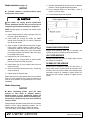
Figure 1. Tractor Stability
DANGER
WARNING
CAUTION
WARNING

14 Operation
MAN1248 (2/26/2018)
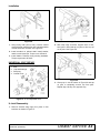
CONNECT CUTTER TO TRACTOR
Tractor Adjustments
Before attaching tractor to cutter, install sway blocks or
sway chains, or adjust stabilizer bars. Refer to the trac-
tor operator's manual for instructions.
Install tractor front end weights as recommended by
the tractor manufacturer to provide 20% of weight on
front wheels.
A minimum 20% of tractor and equipment
weight must be on the tractor front wheels when
attachments are in transport position. Without this
weight, front tractor wheels could raise up result-
ing in loss of steering. The weight may be attained
with front wheel weights, ballast in tires, front trac-
tor weights or front loader. Weigh the tractor and
equipment. Do not estimate.
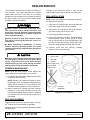
Figure 2. 3-Point Mounting Positions
Category 2 Standard Hitch
1. Position tractor lower lift arms between hitch mast
plates.
2. Insert lower hitch pins to Cat 2 position through
mast plates and tractor lower lift arms in either
upper or lower holes, Figure 2.
3. Secure with lynch pins.
4. Attach top link for mounted units in the second hole
of upper mast for the upper position, and the third
hole for the lower position using top link pin.
Category 3 Standard Hitch
1. Position tractor lower lift arms between hitch mast
plates.
2. Insert lower hitch pins to Cat 3 position through
mast plates and tractor lower lift arms in either the
upper or lower holes, Figure 2.
3. Secure with lynch pins.
4. Attach top link for mounted units in the top (upper)
or second (lower) hole of upper mast using top link
pin.
Category 2 & 3 Quick Hitches
1. Position lower hitch pins to Category 2 position in
either the upper or lower holes Figure 2.
2. Use the upper hole that matches upper quick hitch
point location. This is usually the fifth (lower) or
third (upper) hole for Category 2 and the fourth
(lower) or second (upper) hole for Category 3.
3. Secure with lynch pins.
4. Attach tractor to cutter and secure hitch according
to hitch manufacturer’s instructions.
Make sure spring-activated locking pin or collar
slides freely and is seated firmly in tractor PTO
spline groove.
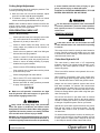
CUTTING HEIGHT & ATTITUDE ADJUST-
MENT
Place tractor and cutter on a level area. Lower cutting
head (parallel to ground but suspended in air). Adjust
tractor 3-point lower arms to position cutter center sec-
tion level from side to side and level with the cutting
head. On some tractors, the left lift arm can telescope
up or be locked down. When using this cutter, it must
be locked down.
Figure 3. Attitude Adjustment
WARNING

Operation 15
MAN1248 (2/26/2018)
Cutting Height Adjustment
It is recommended that level cutting be practiced. This
is done by following these steps:
1. With the lower link from tractor attached, adjust
upper link so that height A equals height B.
2. If tailwheel option is applied, adjust tail wheel
ratchet so that height A and B remain equal.
NOTE: Under conditions where extension and flex are
used in uneven terrain, it may be feasible to employ a
hydraulic top link to the upper hitch.
PRE-OPERATION CHECK LIST
(Owner’s Responsibility)
___ Check hydraulic tank level using dip stick under
cap. Level should be 5" from bottom of stick.
___ Hydraulic oil (in tank) is above 50° F.
___ Check to ensure blades are sharp, secure, and
cutting edges are positioned in the direction of
crossbar rotation.
___ Check to be sure gearbox is half full of 90W
gear
lube and has vent plug installed.
___ Check to ensure PTO shaft universal joints and
all other lubrication points are
properly serviced.
___ Check to ensure all safety shielding is properly
installed and in good condition.
___ Check to ensure PTO shielding rotates freely.
___ Clear mowing area of debris that could be picked
up and thrown by cutter.
___ Check cutting height and cutter attitude.
___ Place tractor PTO and transmission in neutral
before attempting to start engine.
___ Review and follow all safety practices presented
on page 7 through page 13.
NOTICE
■ Make sure all hydraulic connections are tight
and all hydraulic lines and hoses are in good con-
dition before engaging tractor PTO.
Keep hands and body away from pressurized
lines. Use paper or cardboard, not hands or other
body parts to check for leaks. Wear safety goggles.
Hydraulic fluid under pressure can easily penetrate
skin and will cause serious injury or death.
Make sure that all operating and service person-
nel know that if hydraulic fluid penetrates skin, it
must be surgically removed as soon as possible by
a doctor familiar with this form of injury or gan-
grene, serious injury, or death will result.
CONTACT A PHYSICIAN IMMEDIATELY IF FLUID
ENTERS SKIN OR EYES. DO NOT DELAY.
Do not disconnect hydraulic lines until machine
is securely blocked or placed in lowest position
and system pressure is released by operating
valve levers.
GENERAL MOWING
Look down and to the rear and make sure area
is clear behind tractor and cutter before operating
in reverse.
This cutter may be used for mowing in either forward or
reverse. Reverse mowing will enable you to cut close
to obstructions. When mowing in both directions, cutter
should be level front to rear.
Cutter Head Hydraulic Lift
The cutter head is raised with a 3.5" single-acting
hydraulic cylinder. The cylinder, which lifts only, is con-
trolled by the tractor hydraulic controls. The head is
lowered
by gravity.
There is an orifice restrictor in the hydraulic line to con-
trol the descent
When mowing, set hydraulic valve in the neutral posi-
tion, unless using optional gauge wheel(s) then set in
float.
This will allow cutter to follow the ground contour.
Always use the tractor hydraulic system with built-in
float when available. On tractors with closed-center
systems that do not have float, you may lock the con-
trol in the down mode. This will allow the head to float.
Please use Gauge Wheel option while using float oper-
ation. See page 52.
Do not lock the control in the down mode on tractors
with open-center systems. Refer to the tractor owner's
manual or contact your dealer if you have questions as
to the type of hydraulic system used on your tractor.
Operate the open-center system that does not have a
float with the control in the neutral position. This will
not
allow cutter head to float up when encountering
an
obstruction.
For tractors without hydraulic controls, an auxiliary con-
trol valve may be used. It has three positions: pull out
to raise, push in to slightly lower, and push all the way
in and snap into detent to allow cutter head to float.
WARNING
WARNING
WARNING

16 Operation
MAN1248 (2/26/2018)
Operating Extension Cylinder
Verify that transport bar is disengaged from deck and
holstered. Verify that extension is properly greased
before operating. When operating cylinder, make sure
that areas where deck will extend or retract are free of
obstacles. Do not extend or retract the deck as a
means for starting a cutting operation.
NOTICE
■ Never install a double-acting cylinder as dam-
age to the cutter will occur.
Tractor and Cutter Operation
Full chain shielding must be installed at all
times. Thrown objects could injure people or dam-
age property.
• If the machine is not equipped with full chain
shielding, operation must be stopped.
• This shielding is designed to reduce the risk
of thrown objects. The mower deck and protec-
tive devices cannot prevent all objects from
escaping the blade enclosure in every mowing
condition. It is possible for objects to ricochet
and escape, traveling as much as 300 feet
(92m).
Keep bystanders away from equipment.
Never allow riders on power unit or attachment.
This cutter is operated with tractor controls. Engage the
PTO control at idle rpm to prevent undue stress on
tractor, cutter drivelines and gearboxes. Set tractor
PTO speed and tractor throttle to operate at either 540
rpm or 1000 rpm, depending on which model cutter you
have. Change ground travel by using higher or lower
gears. Be sure operator is familiar with all tractor con-
trols and can stop it and the cutter in an emergency.
The operator should give complete, undivided attention
to operating the tractor and cutter when mowing.
Brush and Ditch Bank Mowing
Never direct discharge toward people, animals,
or property.
■ Do not raise cutter head with PTO engaged. A
raised cutter head exposes blades and increases
thrown object hazards. Always operate with cutter
head close to surface being cut.
When operating this cutter on ditch banks and cutting
brush, the operator must be alert. Should the cutter hit
an obstruction, the front of the tractor will usually slide
toward the ditch (to the right). It would be possible to
run the tractor and cutter into the ditch if mowing speed
is too high or operator is not alert. On steep banks, it
may be necessary to use the left turning brake to coun-
teract the load occurring when cutter is hitting brush.
This cutter can handle brush up to 2" without serious
damage if reasonable judgement is used. Sometimes,
in ditches, it is well to raise the hitch and cutter head as
high as needed and then lower it gradually
onto top of
brush. This will produce a good shredding
job and
usually is the best method for heavy brush.
When mowing steep banks with cutter on the uphill
side, it is possible to raise cutter head high enough to
over-center and make it difficult to lower. When this
occurs, it will be necessary to maneuver tractor to
cause lowering to take place.
Hydraulic Drive
All adjustments to the hydraulic drive system have
been made at the factory. It is designed to flow 20 gpm
of oil up to 4000 psi pressure. The pressure relief valve
is set for 4000 psi.
When the mower is overloaded, the pressure relief
valve will operate as oil is by-passed. When this
occurs, stop the tractor, or back up, to start the mower
blades rotating again. Continued by-passing of oil "over
relief" will overheat the unit and can cause damage to
hydraulic components.
The DBH5.31 and DBH6.31 mowers are supplied with
a temperature gauge mounted on top of the reservoir. If
the oil temperature gets over 180°F, stop mowing until
this temperature drops to a safe level. This gauge is to
aid in obtaining maximum use from the mower.
For operating in highly loaded conditions, consider
adding the cooler option to the hydraulic tank. See
page 55.
■ Frequent or continuous contact of blades with
the ground will cause mower hydraulic oil to over-
heat and may cause cutter damage. Be sure to fol-
low initial start-up instructions before operating for
the first time.
DANGER
DANGER
WARNING
WARNING
CAUTION

Operation 17
MAN1248 (2/26/2018)
TRANSPORT
■ Before transporting, stop tractor PTO, raise
cutter hitch, then raise cutter head and
install
transport bar. A raised cutter head can fall
and
crush. Keep away; never go underneath. Lower
cut-
ter head after transport and for storage.
Transport lock-up bar should be used when unit is
under transport.
When transporting the machine or working on the
underside, attach lock-up bar (1) to cutter frame and
secure with safety pin (2).
Engaging Lock-Up Bar
1. Retract deck extension with hydraulic cylinder.
2. Raise deck with deck hydraulic pivot cylinder.
3. Remove safety pin (2) from pin at deck near to
motor.
4. Remove lock-up bar (1) from holster at hitch.
Rotate towards deck.
5. Engage lock-up bar hole to pin. Slide onto pin.
6. Reinstall safety pin (2).
7. To lower deck for operation, retract deck pivot and
extension cylinders. Remove safety pin and return
lock-up bar and pin to storage position.
Figure 4. Lock-Up Bar
STORAGE
Do not disconnect hydraulic lines until machine
is securely blocked or placed in lowest position
and system pressure is released by operating
valve levers.
When unhooking and parking the cutter, lower cutter
head to ground. Lower the jack stand. Lower hitch until
3-point arms
are released and then disconnect. Be
sure to disconnect PTO and hydraulic lines before
moving tractor away.
WARNING
1. Transport lock-up bar
2. Safety pin
WARNING

18 Owner Service
MAN1248 (2/26/2018)
OWNER SERVICE
The information in this section is written for operators
who possess basic mechanical skills. If you need help,
your dealer has trained service technicians available.
For your protection, read and follow the safety informa-
tion in this manual.
■ For service and adjustments, lower center
frame and cutter head to ground and disconnect
cutter driveline from tractor PTO. Raise as needed
for working room and securely block all sections of
this equipment before working underneath. Block-
ing up prevents cutter dropping from hydraulic
leak down, hydraulic system failures, or mechani-
cal component failures.
■ When transporting the machine or working on
the underside, attach lock-up bar as shown on
page 18.
Make sure shields and guards are properly
installed and in good condition. Replace if damaged.
Do not disconnect hydraulic lines until machine
is securely blocked or placed in lowest position
and system pressure is released by operating
valve levers.
Operate tractor PTO at 540 RPM (1000 RPM on Q
Series cutters). Do not exceed.
Always wear relatively tight and belted clothing
to avoid getting caught in moving parts. Wear
sturdy, rough-soled work shoes and protective
equipment for eyes, hair, hands, hearing, and head;
and respirator or filter mask where appropriate.
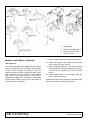
LUBRICATION
■ Lower cutter head to ground, shut off tractor
engine and remove key before servicing.
Do not let excess grease collect on or around parts,
particularly when operating in sandy areas.
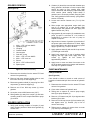
Figure 3 shows the lubrication points. The chart gives
the frequency in operating hours based on normal
operating conditions. Severe or unusual conditions
may require more frequent lubrication. Some reference
numbers have more than one location; be sure to
check number of points.
Use a SAE multi-purpose type grease. Be sure to clean
fitting thoroughly before using grease gun.
Use a good quality 90W gear lube in gearboxes.
Figure 3. Lubrication Points
CAUTION
REF DESCRIPTION FREQUENCY
1 Hitch & Extension 8 Hours
2 Hitch & Extension 8 Hours
3 Deck Hinge 8 Hours
4 Deck Hinge 8 Hours
5 Hydraulic Oil in Tank (5” on Dipstick) Check or Fill
8 Hours
6 Driveline U-Joint 8 Hours
7 Telescoping Shaft 8 Hours
8 Spindle Flange (Fill 1/2 Full With SAE
90W Gear Lube)
8 Hours
9 Gearbox (Fill 1/2 Full With SAE 90W
Gear Lube)
C h e c k o r F i l l
8 Hours
10 Tailwheel Pivot Tube 8 Hours
11 Tailwheel 8 Hours
12 Ratchet Jack 20 Hours
13 Hydraulic Oil Change 500 Hours

Owner Service 19
MAN1248 (2/26/2018)
Gearbox
Each Woods gearbox is equipped with tapered bear-
ings throughout. These bearings are preset at the fac-
tory and normally do not require adjustment during
their useful life. Gearbox must be half full of SAE 90
gear lube. Check every eight hours. If there are any
leaks around bolts or covers, apply #3 Permatex
®
or
Gasket Compound to seal. Check seals to be sure they
do not leak.
Hydraulic Drive Oil Recommendations
Use of type "A" or "F" automatic transmission fluid is
recommended for all ambient temperatures; however,
the following motor oils may be used:
SAE 30-30W for temperatures above 90°F
SAE 20-20W for 35° to 90°F
SAE 10-10W for temperatures below 35°F
Oil level should be checked daily and oil added as nec-
essary to maintain level at full mark on dipstick. Capac-
ity is 35 gallons.
Oil Leaks
Keep hands and body away from pressurized
lines. Use paper or cardboard, not hands or other
body parts to check for leaks. Wear safety goggles.
Hydraulic fluid under pressure can easily penetrate
skin and will cause serious injury or death.
Make sure that all operating and service person-
nel know that if hydraulic fluid penetrates skin, it
must be surgically removed as soon as possible by
a doctor familiar with this form of injury or gan-
grene, serious injury, or death will result.
CONTACT A PHYSICIAN IMMEDIATELY IF FLUID
ENTERS SKIN OR EYES. DO NOT DELAY.
Most oil leaks occur in the tubes, hoses and fittings. If
you have an oil leak, check where the leak is and fix it.
Three types of fittings are used on this machine:
● O-Ring seal fittings on pumps, motors, etc. - A leak
here is usually from a faulty O-ring.
● Pipe fittings - Use Teflon
®
tape to seal these
"thread seal" joints.
● Hose, hose nipple, and clamp fitting - Surfaces
should be in good condition. Hoses should be of
correct size and clamps tightened.
BLADE SERVICING
■ Do not handle blades with bare hands. Care-
less or improper handling may result in serious
injury.
Raise cutter head and lock in up position. Inspect
blades before each use to determine that they are
properly installed and in good condition. Check to be
sure blades are snug but still swivel on blade pin (see
Blade Installation). Replace any blade that is bent,
excessively nicked, worn or has any other damage.
Small nicks can be ground out when sharpening.
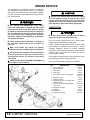
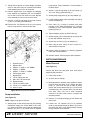
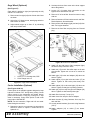
Blade Removal (Figure 4)
Align crossbar and blade pin assembly with blade
access hole in cutter frame. Remove bolt (1) and blade
pin lock clip (5). Slide keyhole plate (4) out of blade pin
groove and remove. Remove spacers and drive pin out
of crossbar.
NOTICE
■ If blade is seized in crossbar and extreme
force will be required to remove it, support cross-
bar from below to prevent gearbox damage.
Figure 4. Blade Removal/Installation
AWARNING
AWARNING
CAUTION
1. 1/2 NC x 1-1/4 HHCS GR5
2. Shim, 18 GA
3. Shim, 20 GA
4. Keyhole plate
5. Blade pin lock clip
6. Blade pin
7. Crossbar
8. Blade

20 Owner Service
MAN1248 (2/26/2018)
Blade Installation (Figure 4)
NOTICE
■ Crossbar rotation is counter-clockwise when
looking down on the cutter.
Your dealer can supply genuine replacement
blades. Substitute blades may not meet original
equipment specifications and may be dangerous.
NOTE: Always replace or sharpen both blades at the
same time.
1. Inspect blade pin (6) for nicks or gouges, and if you
find any, replace the blade pin.
2. Insert blade pin through the blade (8). Blade
should swivel on blade pin; if it doesn’t, determine
the cause and correct.
3. Align crossbar (7) with blade access hole in cutter
frame. Apply a liberal coating of Never Seez
®
or
equivalent to blade pin and crossbar hole. Make
sure blade offset is away from cutter. Push blade
pin through crossbar. Pin should rotate freely prior
to installing blade clip (5).
4. Install shims (2 & 3) over blade pin.
NOTE: Only use enough shims to allow keyhole
plate (4) to slide into blade pin groove.
5. Install blade clip (5) over keyhole plate and into
blade pin groove.
6. Secure into position with cap screw (1). Torque cap
screw to 85 lbs ft.
7. Repeat steps for opposite side.
Blade should be snug but should swivel on pin without
having to exert excessive force. Keep any spacers not
used in the installation as replacements or for future
installation.
Blade Sharpening
NOTICE
■ When sharpening blades, grind the same
amount on each blade to maintain balance.
Replace blades in pairs. Unbalanced blades will
cause excessive vibration which can damage gear-
box bearings. Vibration may also cause structural
cracks to cutter.
Always sharpen all blades at the same time to maintain
balance. Follow original sharpening pattern. Do not
sharpen blade to a razor edge, but leave at least a
1/16" blunt edge. Do not sharpen back side of blade.
1. Sharpen both blades at the same time to maintain
balance. Follow original sharpening pattern.
2. Do not sharpen blade to a razor edge - leave at
least a 1/16” blunt edge.
3. Do not sharpen back side of blade.
Figure 5. Blade Cutting Edge Sharpening
CHAIN SHIELDING REPAIR
Inspect chain shielding each day of operation and
replace any broken or missing chains as required.
OIL FILTER SERVICE
Change cloth filter with each oil change (See Lubrica-
tion section for schedule).
SCREEN FILTER SERVICE
Screen filter is provided to strain out 100 micron or
larger debris and is located inside the hydraulic tank.
Access to filter can be done when oil is changed. (See
Lubrication section for schedule). Inspect screen for
punctured or torn surface. Change or replace as nec-
essary.
CAUTION
Page is loading ...
Page is loading ...
Page is loading ...
Page is loading ...
Page is loading ...
Page is loading ...
Page is loading ...
Page is loading ...
Page is loading ...
Page is loading ...
Page is loading ...
Page is loading ...
Page is loading ...
Page is loading ...
Page is loading ...
Page is loading ...
Page is loading ...
Page is loading ...
Page is loading ...
Page is loading ...
Page is loading ...
Page is loading ...
Page is loading ...
Page is loading ...
Page is loading ...
Page is loading ...
Page is loading ...
Page is loading ...
Page is loading ...
Page is loading ...
Page is loading ...
Page is loading ...
Page is loading ...
Page is loading ...
Page is loading ...
Page is loading ...
Page is loading ...
Page is loading ...
Page is loading ...
Page is loading ...
Page is loading ...
Page is loading ...
-
 1
1
-
 2
2
-
 3
3
-
 4
4
-
 5
5
-
 6
6
-
 7
7
-
 8
8
-
 9
9
-
 10
10
-
 11
11
-
 12
12
-
 13
13
-
 14
14
-
 15
15
-
 16
16
-
 17
17
-
 18
18
-
 19
19
-
 20
20
-
 21
21
-
 22
22
-
 23
23
-
 24
24
-
 25
25
-
 26
26
-
 27
27
-
 28
28
-
 29
29
-
 30
30
-
 31
31
-
 32
32
-
 33
33
-
 34
34
-
 35
35
-
 36
36
-
 37
37
-
 38
38
-
 39
39
-
 40
40
-
 41
41
-
 42
42
-
 43
43
-
 44
44
-
 45
45
-
 46
46
-
 47
47
-
 48
48
-
 49
49
-
 50
50
-
 51
51
-
 52
52
-
 53
53
-
 54
54
-
 55
55
-
 56
56
-
 57
57
-
 58
58
-
 59
59
-
 60
60
-
 61
61
-
 62
62


Ask a question and I''ll find the answer in the document
Finding information in a document is now easier with AI
Related papers
-
Woods DBH5.30 User manual
-
-
-
-
-
Woods Equipment MAN0962 User manual
-
-
-
-
Woods BRUSHBULL BB84.50 User manual
Other documents
-
Boss Office Products B959-BY User guide
-
-
CURT 40081 User manual
-
Ultra-Fab Products 48-979014 User manual
-
 Breeze33 BZ33-WB Mini Split Wall Bracket Installation guide
-
Metrologic MS 1690 Focus Series Stand Installation Manual
-
-
-
 Pacific Handy Cutter PHC100 User manual
-
Toro Weight Kit, GT Classic Tractors Installation guide

