Page is loading ...

Installation Information
PFK9-series
High precision weighing platforms

Congratulations on choosing the quality and precision of METTLER TOLEDO. Proper
use of your new equipment according to this User manual and regular calibration and
maintenance by our factory-trained service team ensures dependable and accurate
operation, protecting your investment. Contact us about a service agreement tailored to
your needs and budget. Further information is available at
www.mt.com/service.
There are several important ways to ensure you maximize the performance of your
investment:
1. Register your product: We invite you to register your product at
www.mt.com/productregistration
so we can contact you about enhancements, updates and important notications
concerning your product.
2. Contact METTLER TOLEDO for service: The value of a measurement is proportional
to its accuracy – an out of specication scale can diminish quality, reduce prots and
increase liability. Timely service from METTLER TOLEDO will ensure accuracy and
optimize uptime and equipment life.
– Installation, Conguration, Integration and Training:
Our service representatives are factory-trained, weighing equipment experts. We
make certain that your weighing equipment is ready for production in a cost
effective and timely fashion and that personnel are trained for success.
– Initial Calibration Documentation:
The installation environment and application requirements are unique for every
industrial scale so performance must be tested and certied. Our calibration
services and certicates document accuracy to ensure production quality and
provide a quality system record of performance.
– Periodic Calibration Maintenance:
A Calibration Service Agreement provides on-going condence in your weighing
process and documentation of compliance with requirements. We offer a variety
of service plans that are scheduled to meet your needs and designed to t your
budget.
2
PFK9-series 30233015C

Contents
1 Safety information for operation in the Exarea ....................................................4
2 Installation ..........................................................................................................6
2.1 Preparatory work ..................................................................................................6
2.2 Setting up ............................................................................................................7
2.3 Levelling ............................................................................................................ 12
2.4 Pit installation ..................................................................................................... 14
2.5 Lengthening and installing connection cable .......................................................... 14
2.6 Equipotential bonding in hazardous areas ............................................................. 15
2.7 Connecting PFK98_APW weighing platforms ......................................................... 16
2.8 Commissioning .................................................................................................. 23
3 Conguration possibilities .................................................................................24
3.1 General information............................................................................................. 24
3.2 Conguration data in the factory setting ................................................................25
4 Planning assemblies..........................................................................................26
4.1 Notes on planning...............................................................................................26
4.2 Preload range .....................................................................................................26
4.3 Mounting possibilities ..........................................................................................27
4.4 Opening possibilities ........................................................................................... 31
5 Dimensions .......................................................................................................35
3
30233015C PFK9-series

1 Safety information for operation in the
Exarea
▲ The PFK9-series high precision weighing platforms provide options for operation in
Category3 or Category 2 / DIV 1 hazardous areas (gases and dusts). There is an
increased risk in injury and damage when using the explosion-protected weighing
platforms in a potentially explosive atmosphere. Special care must be taken when
working in such hazardous areas.
▲ Any protective foils present in the hazardous area, e.g. on the load plate, must always
be removed.
▲ In hazardous areas, the weighing platforms may only be installed, maintained and
repaired by authorized METTLER TOLEDO service personnel.
▲ No modications may be made to the weighing platform and no repair work may be
performed on the system modules. Any weighing platform or system modules that are
used must comply with the specications contained in the installation instructions.
Non-compliant equipment jeopardizes the intrinsic safety of the system, cancels the
"Ex" approval and renders any warranty or product liability claims null and void.
▲ The safety of the weighing system is only guaranteed when the weighing system is
operated, installed and maintained in accordance with the respective instructions.
▲ Also comply with the following:
– the instructions for the system modules,
– the regulations and standards in the respective country,
– the statutory requirement for electrical equipment installed in hazardous areas in
the respective country,
– all instructions related to safety issued by the owner.
▲ The explosion-protected weighing system must be checked to ensure compliance with
the requirements for safety before being put into service for the rst time, following any
service work and every 3 years, at least.
▲ Prevent the build-up of static electricity.
– Always wear suitable working clothes when operating or performing service work
in a hazardous area.
– Avoid strong mechanical rubbing of the powder-coated surfaces against any
material when operating in Category3 or Category 2 / DIV 1.
– Only use the weighing platforms when electrostatic processes leading to propagating
brush discharges are impossible.
▲ Do not use protective coverings for the devices.
▲ Avoid damage to the system components.
▲ If system damage occurs, the system must be put out of operation immediately.
▲ Damaged system components must be replaced immediately.
Competence
Ex approval
Operation
4
Safety information for operation in the Exarea
PFK9-series 30233015C

▲ Only install or perform maintenance work on the weighing system in the hazardous
areas if the following conditions are fullled:
– the intrinsically safe characteristic values and zone approval of the individual
components are in accordance with one another,
– the owner has issued a permit ("spark permit" or "re permit"),
– the area has been rendered safe and no explosive dust is present and the owner's
safety coordinator has conrmed that there is no danger,
– the necessary tools and any required protective clothing are provided (danger of
the build-up of static electricity).
▲ The explosion protected PFK9-series high precision weighing platforms may only be
operated in hazardous areas of Category3 or Category 2 / DIV1 in conjunction with
weighing terminals that have the appropriate approval and interface specication.
▲ The certication papers (certicates, manufacturer’s declarations) must be present.
▲ Before setting up the system secure the connection between weighing terminal and
weighing platform.
▲ Lay cabling securely so that it does not move and effectively protect it against damage.
▲ Only route cables into the housing of the system modules via the approved earthing
cable glands and ensure proper seating of the seals.
▲ The connection cable may not be separated from the weighing terminal while it is
energized.
▲ Make sure that no conductive dusts exist when removing the plug of load cell.
▲ Only use METTLER TOLDEO approved and marked connection cables.
▲ Secure M12 connectors via hexagon nut and appropriate tools.
Torque range: 1.0 to 1.2Nm.
▲ Connect the weighing platform with an equipotential bonding conductor to the system
safety ground.
▲ Protect the M12 ange socket and the cable connector effectively against mechanical
damage by using the assembled protective bracket.
▲ Avoid direct sunlight radiation.
Installation
5
Safety information for operation in the Exarea 30233015C PFK9-series

2 Installation
CAUTION
▲ Use only genuine METTLER TOLEDO accessories and cable assemblies with this
product. Use of anauthorized or counterfeit accessories or cable assemblies may
result in voided warranty, improper or erroneous operation or damage to property
(including the unit) and personal injury.
2.1 Preparatory work
2.1.1 Selecting installation location
▲ The foundation at the installation location must be capable to safely support the
weight of the weighing platform at its support points when it carries the maximum
load. At the same time, it should be so stable that no vibrations occur during weighing
operations. These requirements also apply when the weighing platform is integrated in
conveying systems and the like.
▲ Ensure that the ground at the installation location is even.
▲ Ensure that there are no vibrations from machines near the installation site.
▲ Ensure that there are no drafts at the installation site.
2.1.2 Ambient conditions
• Use powder-coated/hot galvanized weighing platforms only in a dry environment.
• In a damp environment, in wet operation or when working with chemicals: Use
stainless-steel weighing platforms.
2.1.3 Accessories
➜ Completely unpack the accessories provided with the weighing platform.
– 1 bottle of oil, suitable for foodstuffs
– 1 set of measuring data signs for selectable congurations
– Optional: ACC409xx-SICSpro-IDNet converter (incl. identcard kit, not for Category2/
DIV1)
additionally provided for sizes D, E, ES:
– 4 eyebolts in a bag
additionally provided for weighing platforms with foldable load plate:
– 2 eyebolts in a bag
– 1 handle
6
Installation
PFK9-series 30233015C

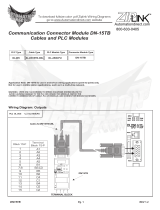
2.2 Setting up
2.2.1 Size C
Setting up
CAUTION
Danger of injury due to the heavy load plate.
▲ Always ask a second person to help removing the load plate.
▲ Wear gloves when removing the load plate.
1. Remove the load plate by pivoting the two side handles (1) outward.
2. Lift the weighing platform off the transport pallet and set it down at the installation
location.
Be careful when lifting it off the pallet to prevent the lever mechanism which is open at
the bottom from being damaged.
3. Unscrew and remove the yellow locking screw (3).
4. Loosen the lever lock and remove the transport lock.
Note
Keep the locking elements for use for transporting the weighing platform in the future.
Routing the connection cable
The connection cable is stored inside the weighing platform during transport for protection.
1. Route out the connection cable under the base frame.
2. Replace the load plate (3) so that the symbol is located above the level indicator.
3. Make sure that the load supports (4) in the corners of the weighing platform are
vertical.
1
2
3
4
7
Installation 30233015C PFK9-series

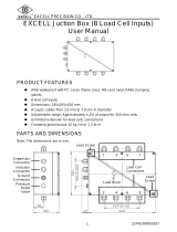
2.2.2 Sizes D / E / ES
Setting up
CAUTION
Danger of injury due to the heavy load plate.
▲ Always move the weighing platforms with the aid of a second person or with an
appropriate tool.
▲ Wear gloves.
NOTICE
Damage to the lever mechanism when using forklift trucks because the lever
mechanism is open at the bottom.
▲ Move up the load forks of the forklift truck and hang the weighing platform on them
as described.
Setting up weighing platforms with xed load plate
1. Lift off the load plate (1) after unscrewing the 6 or 8 screws (2). The eyebolts (3) can
be screwed into the threads after removing the blind screws as lifting aid.
Depending on the shipping warehouse or the model ordered, the load plate may also
be included in separate packing. Then the mounting screws and the blindscrews are
supplied in the accessories bag.
2. Lift the weighing platform off the transport pallet. To do this, screw the four eyebolts
(4) provided into the threads at the corners of the load plate mounting device and lift
off the weighing platform with a crane, block and tackle or similar equipment and set
it down at the installation location.
Setting up weighing platforms with raisable load plate
1. Remove weighing goods or superstructure from the load plate.
2. Use a screwdriver to screw out the cover screw (1).
3. Turn the handle (2) clockwise into the exposed thread until it stops.
4. Position yourself on the right-hand side next to the weighing platform.
1
3
2
4
4
2
1
8
Installation
PFK9-series 30233015C

5. Pull the load plate up using the handle.
DANGER
Danger of injury due to slamming load plate.
▲ Ensure that the gas spring has extended completely.
6. On the right hand side of the weighing platform slide the slot of the supplied safety
wedge (1) onto the load plate.
7. Slide the safety wedge down until it will go no further.
8. Make sure that the catch (2) is on the inner side of the load frame.
The raised load plate is secured and cleaning or service work can be performed safely.
1
2
9
Installation 30233015C PFK9-series

9. Lift the weighing platform off the transport pallet. To do this, screw the two eyebolts
(3) provided (they are located on the inside on the level indicator side) into the
threads of the load frame and lift off the weighing platform with a crane, block and
tackle or similar equipment and set it down at the installation location.
10. Remove the eyebolts.
Releasing lift-off locks and removing transportation locks
1. Loosen the nuts (1) at all 4 corners.
2. Screw up the locking screws (2) and adjust evenly to approx. 1 mm clearance at all
4 corners.
3. Retighten the nuts (1).
4. Remove the lever lock (3) by unscrewing 2 screws.
5. Remove the transportation lock (4).
3
4
6. Mount the lever lock (3) with 2 screws.
3
1
2
1 mm
10
Installation
PFK9-series 30233015C

Routing the connection cable
The connection cable (1) is stored inside the weighing platform during transport for
protection. Depending on the conditions at the installation location, the connection cable
can be routed out as follows:
• Below the weighing platform on the oor
Ideal with the recessing installation of the weighing platform. In the case of above-oor
installation protective cable bridges can be laid up to under the weighing platform.
• Through the base frame
1. Remove the rubber grommet (2) from the hole (3) in the base frame and pull through
the connection cable (1).
2. Push the slotted rubber grommet (2) over the cable and insert it in the hole (3).
Closing weighing platforms with xed load plate
1. Put on the load plate (4) and mount it with the screws (5) (quick-release locks).
2. Screw the blind screws into the threads.
Closing the weighing platform with raisable load plate
WARNING
Crushing hazard
▲ Take care that no items or body parts are between load plate and load frame (danger
zone) of the weighing platform.
1
3
2
5
4
11
Installation 30233015C PFK9-series

3. Slide the safety wedge slightly upwards.
4. Remove the safety wedge from the load plate.
5. Press the load plate down using the handle.
6. Ensure that the load plate latches in and lies evenly on the load frame.
7. Turn out the handle (1) counter-clockwise.
8. Screw the cover screw (2) into the load plate.
2.3 Levelling
Notes
• Only weighing platforms that have been levelled precisely horizontally provide
accurate weighing results.
• Redo levelling when the weighing platform has been moved.
2.3.1 Size C
1. Level the weighing platform with the 4 foot bolts (1) using the level indicator (2): The
air bubble of the level indicator must come to rest within the ring marking.
– With recessed weighing platforms lift off the load plate.
– Use a spanner to adjust the height of the foot bolts.
2. Ensure even contact of the foot bolts. Every foot must stand safely and must have full
contact with its entire surface. Check the stability of the weighing platform by pressing
down on or rocking it at the corners.
3. With recessed weighing platforms put on the load plate.
2.
1.
2
1
21
12
Installation
PFK9-series 30233015C

2.3.2 Sizes D / E / ES
1. Level the weighing platform with the 4 foot bolts (1) using the level indicator (2): The
air bubble of the level indicator must come to rest within the ring marking.
– Lift off or open the load plate.
– Use a screwdriver to adjust the height of the foot bolts underneath the holes (3).
2. Ensure even contact of the foot bolts. Every foot must stand safely and must have full
contact with its entire surface. Check the stability of the weighing platform by pressing
down on or rocking it at the corners.
3. Check the over all height.
– Put a ruler diagonally over corners I and III and check levelness with a water level.
– Adjust the height of the cornes with a screwdriver until they are even.
– Repeat this procedure for cornes II and IV.
4. Lift up the load frame at all 4 corners manually.
The force needed should be approximately the same for all 4 corners.
– If the force is considerably lower at one corner than at the other corners:
Heighten the corresponding corner.
– If the force is considerably higher at one corner than at the other corners:
Lower the corresponding corner.
5. Put on or close the load plate.
2 1
33
I
II
III
IV
13
Installation 30233015C PFK9-series

2.4 Pit installation
The mounting material and detailed instructions for constructing the pit are included with
the "Quick pit for PFK9-series, size C" or "Quick pit for PFK9-series, sizes D / E / ES"
installation kit. The proper construction of the pit according to these instructions is a
requirement.
2.4.1 Size C
1. Carefully lower the weighing platform into the pit. When doing so, also pull the cable
into the empty pipe or cable conduit.
2. Adjust the height of the support feet so that the load plate is ush with the oor.
2.4.2 Sizes D / E / ES
1. Lift off or open the load plate and route out the connection cable under the weighing
platform, see Section 2.2.2.
2. Slowly lower the weighing platform into the pit by the eyebolts. When doing so, also
pull the cable into the empty pipe or cable conduit.
3. Release the lift-off lock, see Section 2.2.2.
4. Adjust ushness with the oor.
To do this, lay spacers (size D: 6 mm, sizes E / ES: 8 mm) on the load frame at the
corners and adjust ush with the upper edge of the pit frame.
Adjust the height of the support feet.
5. To level, see section 2.3.2.
6. Center the weighing platform in the pit with 6 or 8 clamping screws (1) and clamp
them rmly in place. Lock the bolts (1) on the inside of the base frame with the
nuts(2).
7. Either put on the load plate and screw on rmly or fold down the load plate.
2.5 Lengthening and installing connection cable
The connection cable may be lengthened.
Standard version up to 100 m
Ex version up to 50 m
➜ Route the connection cable directly out of the weighing platform to the weighing
terminal or the ConBloc (PFK98_APW weighing platforms only).
CAUTION
If the cable is laid in a pipe, ensure that the pipe is of a sufcient diameter.
2
1
14
Installation
PFK9-series 30233015C

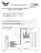
2.6 Equipotential bonding in hazardous areas
EXPLOSION HAZARD
▲ Always use equipotential bonding in hazardous areas.
▲ Use only cables with cross section 4 mm
2
.
The equipotential bonding must be installed by a professional electrician when using the
weighing platform in hazardous areas. METTLER TOLEDO Service only has a monitoring
and consulting function here.
➜ Connect equipotential bonding (PA) of all devices (weighing platform and service
terminal) in accordance with the country-specic regulations and standards. In the
process, make sure that all device housings are connected to the same potential via
the PA terminals.
Location of the equipotential bonding clamp for size C
➜ Mount the equipotential bonding clamp on the base frame alongside the load cell.
Location of the equipotential bonding clamp for size D / E / ES
➜ Mount the equipotential bonding clamp (1) on the base frame.
Equipotential bonding clamp
1 Serrated lock washer A 4.3 DIN 6798
2 Serrated lock washer A 5.3 DIN 6798
3 Hexagonal lock nut M4 DIN 934
4 Washer 5.3 DIN 125, 2 pcs
5 Cheese head screw M5x16 DIN 912
6 Base frame
7 Hexagonal lock nut M5 DIN 934
8 Washer 4.3 DIN 125
9 Equipotential bonding clamp
10 Equipotential bonding plate
Mounting materials are enclosed with the weighing terminal for hazardous areas.
1
1
9
10
1
3
8
2
6
7
5
4
15
Installation 30233015C PFK9-series

2.7 Connecting PFK98_APW weighing platforms
2.7.1 Power supply
Required power supply voltage: 12 to 24 V DC nominal (10 to 29 V DC)
2.7.2 Typical congurations
Direct connection to the PLC in the safe area
To connect the PFK98-APW weighing platform to its environment, the ConBlock respectively
ConBlockIP66 connection module is recommended.
1
D
C
B
A
2
Connection to the PLC via Fieldbus module in the safe area
1
D
C
E
F
B
2
3
EXPLOSION HAZARD
ConBlock / ConBlock IP66 is not approved for hazardous areas.
▲ Only install the ConBlock / ConBlock IP66 in the safe area.
16
Installation
PFK9-series 30233015C

Conguration for Category 3
To connect the PFK98-APW weighing platform to its environment, the ConBlock-X
connection module is recommended.
EXPLOSION HAZARD
▲ Always use a suitable safety barrier to separate equipment located in the hazardous
area from the safe area.
Hazardous area Safe area
1
D
5
C
G
F
B
2
3
Conguration for Category 2 / DIV 1
To connect the PFK98-APW weighing platform to its environment, the APS768x power
supply and the ACM200 interface module are recommended.
Hazardous area Safe area
1
6
C
11
E
11
F
B
7
3
9
8
10
17
Installation 30233015C PFK9-series

METTLER TOLEDO components
1 PFK98_APW weighing platform
2 Connection module
– ConBlock resp. ConBlock IP66 with IP66 housing – for the safe area
– ConBlock-X – for hazardous areas Category 3
3 Fieldbus module (Probus, Pronet, DeviceNet, Ethernet/IP, CC-Link)
4 Fieldbus connection cable, D-Sub 9-pin male, open ends
5 Connection cable M12, 12-pin, open ends, 10 m
6 APS768x – Power supply unit for hazardous area
7 ACM200 interface converter in the safe area
8 Ex-i cable for Category 2 / DIV 1, 4-pin, 10 m, included in the scope of delivery of
ACM200
9 RS232 cable M-to-M
10 Ex-i cable for Category 2 / DIV 1, M12, 6-pin, 10 m
11 Data cable
RS232: x connected to ACM200, 10 m
RS422/485: to be dened by the customer
Customer components
A Connection cable to PLC, RS232 or RS422/RS485
B PLC
C PC or laptop (for conguration and service purpose)
D Standard RS232 cable (DB9 male/female)
E Gender Changer (Male-to-Male)
F Fieldbus cable
G Safety barrier / isolator *
* Safety barrier / isolator is necessary only if limitations for the electrical parameters given
in "2.7.5 Additional technical data for Category 3" on page 22 cannot be held by the
system design.
If these limitations can be held by the system design, there is no need for a safety barrier/
isolator.
18
Installation
PFK9-series 30233015C

2.7.3 ConBlock / ConBlock IP66 connection – safe area
1 System connection side: 10 terminals
2 Weighing platform connection side: 2 x 10 terminals
3 RS232 interface (D-Sub 9), for conguration and servicing
ConBlock connections – weighing platform side
The PFK98_APW weighing platform is delivered with a 12 wire open end cable. The
corresponding terminals of the ConBlock are identied by the wire color and the respective
pin designation.
Pin J D H T F K G E A O
Color – – – – – – – – white brown and green
Signal – – – – – – – – V DC GND
Pin L U P C R B S N M Shield
Color orange black purple violet blue red grey pink yellow braid
Signal Tx+ Rx+ Tx– Rx– CTS GND INT RTS RXD TXD Shield
ConBlock connections – system side
The connection terminal strip is grouped according to the following functions: RS232 and
RS422/RS485 interface, input voltages and digital inputs and outputs.
RS232 RS422 (in) RS422 (through) Power – – –
RXD RTS Rx+ Tx+ Rx+ Tx+ V DC – – –
TXD CTS Rx– Tx– Rx– Tx– GND – – –
GND INT Shield Shield Shield PE – – –
RS422 / RS485 conguration
The RS422 interface is directly avalable via the connection terminals. For the RS485
conguration, the following signals must be connected:
A–: Tx– and Rx–
B+: Tx+ and Rx+
3
1
2
19
Installation 30233015C PFK9-series

Load cell connector
Connector M12 Pin Load cell signal Color
1 V DC in White
2 GND in Brown
3 GND in Green
4 TXD (RS232) Yellow
5 RTS (RS232) Grey
6 RXD (RS232) Pink
7 CTS (RS232) Blue
8 GND (RS232) Red
9 TX+ (RS422) B+ (RS485) Orange
10 TX– (RS422) A– (RS485) Purple
11 RX+ (RS422) B+ (RS485 Black
12 RX– (RS422) A– (RS485) Violet
Shield Braid
2.7.4 ConBlock-X connection
RXD
TXD
RTS
CTS
GNDINT
Rx+
Tx+
Tx-
Tx-
IN1
IN2
IN3
Out1
Out2
Out3
VDCIO
GNDIO
PE
VDC
GNDIO
PE
ConBlock-X connections – weighing platform side
The explosion-protected PFK98_APW weighing platform is delivered with a 12 wire open
end cable. The corresponding terminals of the ConBlock-X are identied by the wire color
and the respective pin designation.
Color Pink Yellow Gray Blue Red Red/blue Violet Black
Gray/
pink
White
Brown/
green
Signal RXD TXD RTS CTS GND INT Rx+ Rx– Tx+ Tx– V DC GND
20
Installation
PFK9-series 30233015C
/