Page is loading ...

LINEA
™
5801(A)/5802(A)
SHELVING
DESIGN MATTHEW WEATHERLY
LET’S GET STARTED.
INSTRUCTION MANUAL


BDIUSA.COM | 3NEED ASSISTANCE? customerservice@bdiusa.com
Congratulations on the purchase of your Linea Shelving 5801(A) / 5802(A) from BDI.
Your shelving has been designed to provide a lifetime of enjoyment. This manual will
provide you with assembly instructions and other helpful information that will ensure
that you get the most out of your shelving. Please save it for future reference.
Your Linea shelving has been engineered for simple assembly. Please follow these
directions carefully to prevent any damage.
Should you need further assistance, contact BDI at customerservice@bdiusa.com.
ENJOY!

4 | BDIUSA.COM LINEA 5801(A) / 5802(A)
PART #
TI
DESCRIPTION
Phillips Screwdriver
QUANTITY
1
PART #
H1
DESCRIPTION
M6 x 35mm Screw
QUANTITY
12 per unit
PART #
T2
DESCRIPTION
Hex Driver
QUANTITY
1
PART #
T3
DESCRIPTION
Leveler Wrench
QUANTITY
1
PART #
H2
DESCRIPTION
Cam Bolt
QUANTITY
4 per unit
PART #
H4
DESCRIPTION
Barrel Nut
QUANTITY
4 per unit
PART #
H3
DESCRIPTION
Wooden Dowel
QUANTITY
8 per unit
PART #
C3
DESCRIPTION
Cabinet Block
QUANTITY
2 per unit
PART #
H11
DESCRIPTION
Shelf Pin
QUANTITY
16 per unit
HARDWARE AND COMPONENTSHARDWARE AND COMPONENTS
Unpack and identify the parts listed below. Note that some components are shipped inside the
cabinet. The assembly workspace should be a non-marring surface such as carpet. For missing
hardware pieces, please contact BDI Customer Service at customerservice@bdiusa.com.
Do not use power tools for assembly of this product.
For all other concerns, please contact your BDI retailer.

BDIUSA.COM | 5NEED ASSISTANCE? customerservice@bdiusa.com
PART #
C6
DESCRIPTION
Outer Glass Shelf
QUANTITY
3 per unit
PART #
C7
DESCRIPTION
Inner Glass Shelf
QUANTITY
1 per unit
PART #
C4
DESCRIPTION
Top Panel
QUANTITY
1 per unit
PART #
C5
DESCRIPTION
Cabinet
QUANTITY
1 per unit
PART #
C1
DESCRIPTION
End Panel
QUANTITY
2 per Base Unit
PART #
C2
DESCRIPTION
Inner Panel
QUANTITY
1 per extension unit
HARDWARE AND COMPONENTS
Holes on 1 side Holes on 2 sides
5801/5801A
5802/5802A
5801/5801A 5802/5802A

6 | BDIUSA.COM LINEA 5801(A) / 5802(A)
PART #
H5
DESCRIPTION
Wall Bracket
QUANTITY
1
PART #
H10
DESCRIPTION
Bracket Screw
QUANTITY
1
PART #
H6
DESCRIPTION
Cabinet bracket
QUANTITY
1
PART #
H7
DESCRIPTION
Fastener Screw
QUANTITY
2
PART #
H8
DESCRIPTION
Sheetrock Anchor
QUANTITY
2
PART #
H9
DESCRIPTION
Plaster/block Anchor
QUANTITY
2
Wall Mounting Kit
HARDWARE AND COMPONENTSHARDWARE AND COMPONENTS


8 | BDIUSA.COM LINEA 5801(A) / 5802(A)
STEP 1. ATTACH CABINET BLOCKS TO END PANELSASSEMBLY
Attach 1 (C3) Cabinet Block to each (C1) End
Panel using (H1) Screws and (T2) Hex Wrench.
H1
H1
C3
C3
H1
H1
Lower End
C1
C1
PART/DESCRIPTION QTY
T2-HEX DRIVER 1
H1-SCREW 4
C3-CABINET BLOCK 2

BDIUSA.COM | 9NEED ASSISTANCE? customerservice@bdiusa.com
ASSEMBLY
STEP 2. INSTALL CAMS AND DOWELS
Find the sets of 3 holes near the top edge of the
(C1) Side Panels. Screw (H2) Cam Bolts into the
threaded holes using (T1) Phillips Screwdriver and
push (H3) Wooden Dowels into the outer holes.
PART/DESCRIPTION QTY
T1-PHILLIPS
SCREWDRIVER
1
H2-CAM BOLT 4
H3-WOODEN DOWEL 8
H2
H3
H3
H3
H3
H2
Lower End
C1
C1

10 | BDIUSA.COM LINEA 5801(A) / 5802(A)
PART/DESCRIPTION QTY
H4-BARREL NUT 4
Insert 4 (H4) Barrel Nuts into the holes on the
top of the (C4) Top Panel making sure that the
hole on the side of the barrel nuts align with the
holes on the edges of the panel.
H4
H4
H4
H4
H4
C4
C4
Align hole
5802
5801
C4
NOTE: Look into side hole of the barrel nuts and make
sure the set screw is not blocking the hole.
If the hole is blocked, unscrew set screw a few turns
until the hole is clear.
This will allow the cam bolts to enter.
STEP 3. INSERT BARREL NUTSASSEMBLY
H4
H4
H4
H4

BDIUSA.COM | 11NEED ASSISTANCE? customerservice@bdiusa.com
Attach (C4) Top Panel to (C1) End Panel by
sliding dowels and cam bolts into the holes on the
edge of (C4) Top Panel. If cams don’t go into
barrel nuts, check to make sure the barrel nut is
aligned with the side hole and make sure the set
screw is loosened prior to insertion of the cam bolts.
Tighten barrel nuts using (T1) Phillips Screwdriver with a clockwise turn. Position (C5) Cabinet as
shown. Make sure rectangular opening on back of cabinet is facing upward towards (C4) Top Panel.
Make sure the door is facing upward.
PART/DESCRIPTION QTY
T1-PHILLIPS
SCREWDRIVER
1
C1
C4
C5
Barrel nut
Door(s) up
Rectangular opening here
Holes on this side
ASSEMBLY
STEP 4. ATTACH TOP PANEL TO SIDE PANEL
C1
C4

12 | BDIUSA.COM LINEA 5801(A) / 5802(A)
Attach the next (C1) End Panel to the other side of
(C4) Top Panel by sliding dowels and cams into the
holes on the side of (C4) Top Panel. Tighten barrel
nuts using (T1) Phillips Screwdriver.
PART/DESCRIPTION QTY
T1-PHILLIPS
SCREWDRIVER
1
C1
C4
STEP 5. ATTACH SECOND END PANELASSEMBLY

BDIUSA.COM | 13NEED ASSISTANCE? customerservice@bdiusa.com
Making sure the bottom of the cabinet is against
the (C3) Cabinet Blocks, carefully open the
cabinet door and attach the (C5) Cabinet to
(C1) End Panels using 8 (H1) Screws and tighten
with (T2) Hex Driver.
PART/DESCRIPTION QTY
T2-HEX DRIVER 1
H1-SCREW 8
ASSEMBLY
STEP 6. ATTACH CABINET TO END PANELS
C3
C5
C1
C1
H1
H1
H1
H1
H1
H1
C1
C1
C5

14 | BDIUSA.COM LINEA 5801(A) / 5802(A)
With help from another person, carefully stand the cabinet onto its base. Carefully walk it into position.
Attaching your Linea shelving to the wall is required to ensure your safety. Use painter’s tape to
mark at least 1 upper back corner of the unit, as shown.
Painter’s tape
STEP 7. STAND UP / WALL CONNECTIONASSEMBLY
2 PERSON TASK

BDIUSA.COM | 15NEED ASSISTANCE? customerservice@bdiusa.com
Move the cabinet to the side. Place (H5) Wall
Bracket on the wall (flush with top and 1/4"
(7mm) away from edge) and mark hole locations
on the wall using a pencil. Drill holes at these
locations for wall inserts.
Choose (H8) or (H9) Wall Anchors appropriate
for your wall type.
Insert (H8) or (H9) Wall Anchors into the holes and attach (H5) Wall Bracket to the wall using
2 (H7) Anchor Screws.
Sheetrock Anchor
Choose wall anchors based on your walls:
Plaster/Brick/Block Anchor
H7
H7
H5
H8
H9
H8/H9
H8/H9
ASSEMBLY
STEP 8. WALL CONNECTION (continued)
PART/DESCRIPTION QTY
H5-WALL BRACKET 1
H7-SCREW 2
H8-ANCHOR 2
H9-ANCHOR 2
1/4"
7mm
H5

16 | BDIUSA.COM LINEA 5801(A) / 5802(A)
Re-position your Linea cabinet in front of the
(H5) Wall Bracket. Stand on a step ladder and slide
(H6) Cabinet Bracket down into the slot in
(H5) Wall Bracket and tighten using (H10) Bracket
Screw and (T2) Hex Driver.
H6
H10
STEP 9. WALL CONNECTION (continued)ASSEMBLY
2 PERSON TASK
PART/DESCRIPTION QTY
T2-HEX DRIVER 1
H6-CABINET BRACKET 1
H10-BRACKET SCREW 1

BDIUSA.COM | 17NEED ASSISTANCE? customerservice@bdiusa.com
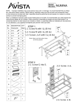
Attach 16 (H11) Shelf Pins into the threaded holes
using a (T1) Phillips Screwdriver—choose preferred
interior shelf height. Install (C6) Outer Glass
Shelves on the shelf pins, tilting the glass slightly
to avoid hitting side panels. Tilt and install (C7)
Inner Glass Shelf inside the cabinet.
Use (T3) Leveler Wrench to level the cabinets.
C6
C6
C6
C7
T3
T1
H11
ASSEMBLY
STEP 10. INSTALL SHELVES AND LEVEL
PART/DESCRIPTION QTY
T1-PHILLIPS
SCREWDRIVER
1
T3-LEVELER WRENCH 1
H11-SHELF PIN 16

18 | BDIUSA.COM LINEA 5801(A) / 5802(A)
The door on your Linea 5801 Cabinet can be
attached to the opposite side (if desired) allowing
the door to swing to the right. Remove the 2 screws
holding each hinge plate to the side of the cabinet
using (T1) Phillips Screwdriver and flip the door
(top becomes bottom) and attach to the threaded
holes on the opposite side using the same screws.
Proceed to page 30.
ASSEMBLY
PART/DESCRIPTION QTY
T1-PHILLIPS
SCREWDRIVER
1
CHOOSE DOOR POSITIONFINE TUNING

BDIUSA.COM | 19NEED ASSISTANCE? customerservice@bdiusa.com
Endless Possibilities
Linea can be configured in endless ways. Below are a few examples. Configurations up to 3 units
wide may be assembled on the floor, stood up and carefully positioned. It is also possible to
assemble 1 unit, stand it up and add additional units to it. Every configuration requires 1 base unit
and then additional units. Base units come with 2 end panels and each add on unit always includes
1 inner panel.
5801 + 5802A +5801A
5801 + 5801A 5802 + 5802A
5801 + 5802A 5802 + 5801A
CONFIGURATIONS

20 | BDIUSA.COM LINEA 5801(A) / 5802(A)
Hybrid Assembly
The following pages will show how to assemble a kit of 2 units shown below—which is a 5802 and a
5801A. Your configuration may differ, but the assembly method will be the same.
5802 (Base) + 5801A (Add-on)
HARDWARE AND COMPONENTSHYBRID KIT
End Panel
Inner Panel
End Panel
/