Page is loading ...

Dust Networks™
Eterna
®
Evaluation & Development
DC9006A and DC9004B User
Guide
Interface Card &
Programming JTAG Adapter

Table of Contents
About This Guide...........................................................................................3
Audience....................................................................................................3
Related Documents......................................................................................3
Conventions and Terminology .......................................................................3
Revision History ..........................................................................................4
Getting Started .............................................................................................5
DC9006 Interface Card.................................................................................5
Installation.................................................................................................5
Setup ........................................................................................................6
Warning.....................................................................................................6
Interface Card (DC9006A) ............................................................................7
Block Diagram ............................................................................................7
USB Interface .............................................................................................7
JTAG ......................................................................................................7
SPI ........................................................................................................7
CLI.........................................................................................................8
API ........................................................................................................8
Signal & Power Isolation...............................................................................8
Power Switch-Over ......................................................................................8
Mote Current Sensing...................................................................................8
Jumper Settings..........................................................................................9
Interface Signal Disconnection.....................................................................10
External JTAG & Reset Pushbutton ...............................................................10
Eterna Evaluation and Development Mote Socket Pinout ..............................11
Programming Adapter (DC9004B) ..............................................................12
Introduction..............................................................................................12
Usage......................................................................................................13
Interfaces.................................................................................................13
DC9006 Interface...................................................................................13
Programming Interface Headers (2x5 0.050”, 2mm and .100” pitch) .............13
JTAG and SWD Interfaces (2x5 2mm” pitch header)....................................14
LTP5900 Socket (26-pin, 2mm pitch)........................................................15
Limitations ...............................................................................................16
Ribbon Cable Length...............................................................................16
Voltage Level.........................................................................................16
Current Limit.........................................................................................16
Feature Comparison with DC9010................................................................16
2 A
NALOG DEVICES, INC. CONFIDENTIAL DC9006A AND DC9004B USER GUIDE

About This Guide
This document describes the DC9006 and DC9004B Eterna Evaluation &
Development boards. The latest revision of this document may be found online at:
www.linear.com/docs/58003
.
Audience
This document is intended for system, hardware and software developers.
Related Documents
The following related documents are available:
DC9006 & DC9004 User Guide
DC9006A Interface Card Design Data
DC9004 Design Files
DC9007A SmartMesh
®
WirelessHART Starter Kit
DC9021B SmartMesh IP RF Certified Starter Kit
DC9022A SmartMesh WirelessHART RF Certified Starter Kit
SmartMesh IP Easy Start Guide
SmartMesh WirelessHART Easy Start Guide
LTC5800-IPM SmartMesh IP Mote Datasheet
LTC5800-IPR SmartMesh IP Manager Datasheet
LTC5800-WHM SmartMesh WirelessHART Mote Datasheet
Eterna Board Specific Parameter Configuration Guide
Eterna Serial Programmer Guide
Eterna 5800 Integration Guide
TAG-Connect TC2050-IDC
and TC2030-CTX-20
DC9010 Online Documentation
IAR I-Jet
and Segger J-Link
Conventions and Terminology
This guide uses the following text conventions:
•
Computer type indicates information that you enter, such as a URL.
• Bold type indicates buttons, fields, and menu commands.
• Italic type is used to introduce a new term.
• Note: Notes provide more detailed information about concepts.
• Caution: Cautions advise about actions that might result in loss of data.
• Warning: Warnings advise about actions that might cause physical harm to the
hardware or your person.
DC9006A
AND DC9004B USER GUIDE ANALOG DEVICES, INC. CONFIDENTIAL 3

Revision History
Revision Date Description
1
May 19, 2017 First Release
2
July 11, 2017 Added footer ADI Confidential notice
Internal Document Number: 040-0132
4 A
NALOG DEVICES, INC. CONFIDENTIAL DC9006A AND DC9004B USER GUIDE

DC9006A
AND DC9004B USER GUIDE ANALOG DEVICES, INC. CONFIDENTIAL 5
Getting Started
DC9006 Interface Card
The DC9006 Interface Card is a USB interface for Eterna Evaluation & Development
Mote such as the DC9018.
The DC9006 may also be used as a programmer when connected to a DC9004B
adapter card. In this case, the DC9006 provides access to any Eterna platforms that
feature the recommended programming connectors.
The DC9006 Interface Card is to be used when communication over USB,
programming or JTAG access is desired. It provides power to the Eterna Evaluation
& Development Mote and an isolated interface to the USB host.
The Interface Card also features test points to monitor the mote current
consumption and jumpers for various configurations.
Figure 1 DC9018B Mote (left) connected to the DC9006A Interface Card (right)
Installation
The Interface Card communicates with a host computer using a USB serial
connection. When the Interface Card is first connected, the host computer may
prompt to install a driver for it.
The Interface Card requires USB drivers from Future Technology Devices
International (FTDI, http://www.ftdichip.com/
). The FTDI “D2XX” drivers can be
found at http://www.ftdichip.com/Drivers/D2XX.htm
.
The FTDI serial chip set is found in many different devices and it is possible that a
version of the FTDI drivers are already installed on your machine. It is important to
use the latest version available on the web. The Interface Card has been tested
against D2XX Drivers revision 2.08.30.

Once drivers are installed for the Interface Board, one should use the same USB port
each time the manager is connected to the computer. If a different USB port is used,
the setup procedure will need to be repeated for that port.
The Eterna Evaluation and Development Board Set require Windows 7 or Windows
XP with SP3, or later versions of Windows.
For details regarding the FTDI drivers installation, please refer to the FDTI
documentation and the Eterna Serial Programmer Guide.
Setup
For details on operating the Eterna Evaluation & Development Board Set in a
network, please refer to the starter kit documentation (SmartMesh IP Easy Start
Guide or SmartMesh WirelessHART Easy Start Guide).
Warning
The Eterna Evaluation & Development system includes Lithium batteries.
Batteries can explode, ignite, leak, or cause personal injury if not used or disposed of
properly. Do not open batteries, discard in fire, nor heat above 100°C (212°F). Do
not recharge the batteries, install them backwards, install used or other battery
types, nor expose battery contents to water.
6 A
NALOG DEVICES, INC. CONFIDENTIAL DC9006A AND DC9004B USER GUIDE

DC9006A
AND DC9004B USER GUIDE ANALOG DEVICES, INC. CONFIDENTIAL 7
Interface Card (DC9006A)
Block Diagram
The following diagram depicts the main features of the DC9006 Interface Card.
Figure 2 Diagram of the DC9006 Interface Card (right)
USB Interface
The Interface Card communication interface to the USB host consists of four serial
ports. After the FTDI driver installation, sequential serial ports are allocated to the
Interface Board.
JTAG
JTAG is only supported with an external JTAG device (not included), such as I-Jet
from IAR with a 20pin .1” adapter or J-Link from Segger. The external JTAG device
must be connected to the JTAG Header depicted in Figure 2 and JP1 jumper must be
installed in the “JTAG EXT” position (see Jumper Settings section).
The USB JTAG connection shown in dotted line in Figure 2 is not supported.
SPI
The second USB serial port is connected to the Eterna Evaluation & Development
Mote slave serial interface (when JP1 “SPI OFF” jumper is not installed).
Further documentation on this interface is available in the Eterna Serial
Programmer Guide.

CLI
The third USB serial port provides access to the UARTC0_TX and UARTC0_RX
lines of the LTC5800 (when JP1 “CLI OFF” jumper is not installed).
A 2-wire serial interface is supported; typically 9600 baud, the baud rate is
application dependant and is described in the Eterna Board Specific Parameter
Configuration Guide.
API
The fourth USB serial port provides access to the serial API of the Eterna Evaluation
& Development Board EManager (when JP1 “API OFF” jumper is not installed).
The API serial interface supports from 2-wire to 6-wire communication. Typically
115200, the baud rate is application dependant and is described in the Eterna Board
Specific Parameter Configuration Guide..
Signal & Power Isolation
The Interface Card provides isolated power and signals to the Eterna Evaluation &
Development Board from the USB micro-B interface (J1).
The external JTAG connector (P1) features signals that are directly connected to the
Eterna Evaluation & Development Board connector. P1 signals are referenced to the
isolated ground.
Power Switch-Over
The Interface Card compares its VCCA rail to the battery voltage from the Eterna
Evaluation & Development Board. When the VCCA rail is within 150 mV of the
battery voltage, the PGOOD signal is asserted.
The Eterna Evaluation & Development Board uses the PGOOD signal to switch its
supply from battery to the power provided by the Interface Card (VUSB_3V6).
Mote Current Sensing
The Interface Card provides two current sensing headers (P3 and P4) working in
conjunction with the JP5 jumper as shown in the schematics below.
With JP5 jumper installed, a voltmeter across P4 will measure the mote
consumption: P4 voltage is equal to 10 times the mote current (voltage drop across
the 10-ohm sense resistor R55 caused by the ISO_VSUPPLY current).
Alternatively and with JP5 is removed, a ammeter may be connected across P3 to
directly measure the mote current.
8 A
NALOG DEVICES, INC. CONFIDENTIAL DC9006A AND DC9004B USER GUIDE

DC9006A
AND DC9004B USER GUIDE ANALOG DEVICES, INC. CONFIDENTIAL 9
VSENSE
VCCA
R55
10.0, 1%
0402
P3
HDR_100MIL_PTH
2
1
P4
HDR_100MIL_PTH
2
1
ISO_VSUPPLY
JP5A
HDR_2MM_PTH
1
2
JP5B
RED JUMPER
AddOn
CURRENT
Figure 3 Current Sensing Jumpers
A third 0.100” header P2 is provided for ground reference. Both P2 pins are
connected to the isolated ground.
For accurate current measurements, all JP1 headers shall be installed (see section:
Mote Signal Disconnection).
Note: In applications where a high current is required, jumper P4 shall be installed;
this shunts the sense resistor R55 and eliminates the associated voltage drop.
Jumper Settings
The Interface Card features the jumper loading options depicted below.
Figure 4 Interface Card Jumpers
The 2mm shorting jumpers may be installed according to the following table:
Jumper Description Default Note
JP1
Disconnect signals to the Eterna Evaluation and Development
Board, install JP1 jumpers as follows:
"JTAG EXT" to enable the External JTAG port, this jumper
ON

10 A
NALOG DEVICES, INC. CONFIDENTIAL DC9006A AND DC9004B USER GUIDE
Jumper Description Default Note
disconnects the JTAG lines from one of the USB serial interface and
should always be installed unless the USB JTAG interface is
supported in the development or evaluation tools;
"SPI OFF" to disconnect SPI lines, RESETn and FLASH_P_ENn;
"CLI OFF" to disconnect UARTC0 TX and RX; and,
"API OFF" to disconnect serial API signals.
OFF
OFF
OFF
JP5
Carries current to the Eterna Evaluation and Development Board.
JP5 should always be installed unless an ammeter is connected
across the P3 header.
ON
JP7
Enables the VCCA rail, the 3.6V isolated power supply to the Eterna
Evaluation and Development Board. JP7 should normally be
installed in the “ON” position (pin 1 & 2); the “OFF” position (pin 2
& 3) may be used to disable the VCCA rail and provide power from
an external source.
ON (1)
JP8
Controls the isolated supplies of the Interface Card (V+ and the
derived VCCA and +5V rails). JP8 should normally be installed in
the “ON” position (pin 1 & 2); the “OFF” position (pin 2 & 3) may be
used to disable the on-board generation of the isolated V+ supply
and provide power from an external source set between 9V and 12V.
ON (1)
JP9
Controls a power switch on the USB 5V supply. JP8 should
normally be installed in the “ON” position (pin 1 & 2); the “OFF”
position (pin 2 & 3) may be used to disconnect the Interface Card
from the USB 5V supply.
ON
(1)
JP10
Connects the Eterna Evaluation and Development Board battery to
logic that determines when power is to be switched from battery to
the isolated VCCA rail. JP10 jumper should normally be installed
for proper power switching operation. JP10 jumper may be
removed to prevent battery current flow in special situations such as
unpowered Interface Card connected to the Eterna Evaluation &
Development Board.
ON
(1) when no jumper is installed, the Interface Card defaults to the “ON” state
Interface Signal Disconnection
To perform accurate current measurements, it is recommended to disconnect the
Interface Card signals from the Eterna Evaluation & Development Board by
installing all JP1 jumpers.
Since so little power is required by the LTC5800 to operate, the Eterna Evaluation &
Development Board may gather enough power from current flowing through the
Interface Card signals and its ESD protection diodes.
External JTAG & Reset Pushbutton
The external JTAG connector (P1) allows the use of 3
rd
party development systems
with the Eterna Evaluation & Development Board. P1 is a 2x10 pin .100” header
compatible with JTAG/SWD emulators such as IAR or Segger J-Link.
The Interface Card features a momentary push button (PB1). PB1 only asserts the
JTAG and the Eterna Evaluation & Development Board reset signal (RESETn).

DC9006A
AND DC9004B USER GUIDE ANALOG DEVICES, INC. CONFIDENTIAL 11
U1
ISL43L210
SC70
IN
1
V+
2
GND
3
NC
4
COM
5
NO
6
ISOOC_RESETn
R8
10k
0201
VCCA
ISOOC_RESETn
MOTE RESET
ISO_MOTE_OFFn
R10
00201
NoStuff
PB1
SPST-NO
SWT3-G
1
2
C49
0.1uF
0201
R83
10k
0201
R38
100k
0201
Q3
DMN2004
SC70-3
1
2 3
VCCA_SW
EXT. JTAG & SWD CONNECTOR
ISOSW_TCK
ISOSW_TMS
ISOSW_TDI
P1
100MIL_VERT_SHR
HDR2X10BOXED
2
4
6
8
1
3
5
7
910
12
14 13
11
1516
1718
1920
ISOSW_TDO
R2
00201
R9
1k0201
R3
00201
NoStuff
ISO_MOTE_OFFn
ISO_MOTE_OFFn
Figure 5 External JTAG Pinout, Reset & Vsense Logic
Eterna Evaluation and Development Mote Socket Pinout
The following table shows the pinout of the socket connector to the Eterna
Evaluation and Development Board.
Pin # Signal Direction
Pin # Signal Direction
1 UART_TX_CTSn O 2 UART_TX_RTSn I
3 UART_TX I 4 GND -
5 UART_RX O 6 UART_RX_RTSn O
7 UART_RX_CTSn I 8 UARTC0_TX/UARTC1_TX I
9 UARTC0_RX/UARTC1_RX O 10 GND -
11 RESETn O 12 FLASH_P_ENn (GPIO2) I/O
13 IPCS_MISO (GPIO6) I/O 14 IPCS_MOSI (GPIO5) I/O
15 IPCS_SSn (GPIO3) I/O 16 IPCS_SCK (GPIO4) I/O
17 GND - 18 TCK O
19 TMS O 20 TDO I
21 TDI O 22 VUSB_3V6
Power
Out
23 PGOOD O 24 GND -
25 VBATTERY I 26 KEY NC
27 Reserved (EHORBAT) I/O 28 Reserved (MOTE_OFF) I/O
29 Reserved (GPIO1) I/O 30 Reserved (GPIO2) I/O
31 V+
Power
Out
32 +5V
Power
Out
Signal direction is relative to the DC9006;
Highlighted signals provide reserved connections for the evaluation of energy harvesting solutions
Connector: Samtec SSW-116-02-F-D or SSW-116-02-F-D-RA-025 (polarized right angle)
Warning: Connector pin numbering is custom, refer to layout for details.

12 A
NALOG DEVICES, INC. CONFIDENTIAL DC9006A AND DC9004B USER GUIDE
Programming Adapter
(DC9004B)
Introduction
The DC9004B Programming Adapter enables the DC9006 Interface card to connect
to a variety of interfaces on a customer board featuring an Eterna chip.
The DC9004B supports the following customer board connections:
• the 2x5 2mm pitch programming header, described in the integration guide;
• a .050” pitch variant of the programming header;
• a 2x5 surface mount programming footprint, matching the Tag-Connect
TC2050-IDC ribbon cable with a 100” socket;
• the 2x5 2mm pitch JTAG header described in the integration guide; and,
• a 2x3 surface mount SWD footprint matching Tag-Connect TC2030-CDX
cable for the IAR I-Jet MIPI-20 connector.
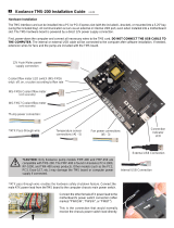
Figure 6 DC9004B installed on a DC9006 (left)

DC9006A
AND DC9004B USER GUIDE ANALOG DEVICES, INC. CONFIDENTIAL 13
Usage
For a non-powered customer board, where the customer board is powered by the
VSUPPLY and GND signals of the DC9004, simply connect the ribbon cable.
For an independently powered customer board, first place the DC9006 JP7 jumper
(see Figure 4) in the “OFF” position, then connect the ribbon cable. Note that in this
configuration the DC9006 will draw some power from the customer board to power
some of its circuitry.
Figure 7 Connecting an Eterna Design to the DC9004B
Interfaces
DC9006 Interface
The interface to the DC9006 consists of a 0.1” pitch 2x16 header with the same
signals described in section “Eterna Evaluation and Development Mote Socket
Pinout”.
Programming Interface Headers (2x5 0.050”, 2mm and .100” pitch)
The programming headers are indicated with the marking “ESP” on the DC9004B
silkscreen.
The following table describes the pinouts of P2 (MOLEX/87833-1020), P3
(SAMTEC/FTSH-105-01-F-DV-K) and P5 (SAMTEC/TST-105-04-L-D-RA).
Pin # Signal Direction
Pin # Signal Direction
1 IPCS_SSn O 2 FLASH_P_ENn O
3 IPCS_SCK O 4 IPCS_MOSI O
5 IPCS_MISO I 6 RESETn O
7 VSUPPLY - 8 GND -
9 UARTC0_TX/UARTC1_TX I 10 UARTC0_RX/UARTC1_RX O
Signal direction is relative to the Programming Adapter board.
The .100” pitch programming connector (P5) is intended to be used in conjunction
with the TC2050-IDC cable from Tag-Connect, described in http://www.tag-
connect.com/TC2050-IDC.

14 A
NALOG DEVICES, INC. CONFIDENTIAL DC9006A AND DC9004B USER GUIDE
In order to use the Tag-Connect TC2050-IDC cable, a surface mount footprint
located on the customer board shall match the following pin numbering.
VSUPPLY
GND RESETn
CLI_TX
CLI_RX
IPCS_MOSI
IPCS_SCK IPCS_MISO
FLASH_P_ENn
IPCS_SSn
Figure 8 Tag-Connect Programming Footprint
JTAG and SWD Interfaces (2x5 2mm” pitch header)
The following table describes the pinout of the JTAG P6 (MOLEX/878321020).
Pin # Signal Direction
Pin # Signal Direction
1 TCK O 2 GND O
3 TMS O 4 TDO I
5 GND - 6 TDI O
7 GND - 8 RESETn -
9 VSUPPLY - 10 NC -
Signal direction is relative to the Programming Adapter board.
The following table describes the pinout of the SWD (“Single Wire Debug”) P4
(SAMTEC/FTSH-110-01-L-DV-K-P). P4 is intended to be used in conjunction with
the TC2030-CTX-20 cable from Tag-Connect, described in http://www.tag-
connect.com/TC2030-CTX-20.
Pin # Signal Direction
Pin # Signal Direction
1 NC (VCC) - 2 TMS (SWDIO) O
3 GND - 4 TCK (SWCLK) O
5 GND - 6 TDO (SWO) I
7 NC - 8 TDI O
9 GND - 10 RESETn -
1 NC - 12 NC -
3 NC - 14 NC -
5 GND - 16 NC -

DC9006A
AND DC9004B USER GUIDE ANALOG DEVICES, INC. CONFIDENTIAL 15
Pin # Signal Direction
Pin # Signal Direction
7 GND - 18 NC -
9 GND - 20 NC -
Notes:
Pin#1 may be connected to VSUPPLY when P8 jumper is installed (not recommended with self -
powered board).
Signal direction is relative to the Programming Adapter board.
The Tag-Connect cable TC2030-CTX-20 only support SWD mode and connect the
following signals to the customer board footprint below.
VSUPPLY GNDRESETn
TMS TDOTCK
Figure 9 Tag-Connect SWD Footprint
LTP5900 Socket (26-pin, 2mm pitch)
The following table describes the pinouts of J1/J2 (SAMTEC/MMS-113-02-L-SV).
Pin # Signal (J1) Dir.
Pin # Signal (J2) Dir.
1 UARTC0_RX (UARTC1_RX) O 1 NC -
2 UARTC0_TX (UARTC1_TX) I 2 NC -
3 GND - 3 RESETn O
4 VSUPPLY - 4 IPCS_SSn O
5 KEY - 5 KEY -
6 UART_RX O 6 IPCS_MISO I
7 UART_TX I 7 IPCS_MOSI O
8 UART_RX_RTSn O 8 IPCS_SCK O
9 UART_TX_RTSn I 9 TCK O
10 UART_RX_CTSn I 10 TDO I
11 UART_TX_CTSn O 11 TDI O
12 NC - 12 TMS O

16 A
NALOG DEVICES, INC. CONFIDENTIAL DC9006A AND DC9004B USER GUIDE
Pin # Signal (J1) Dir.
Pin # Signal (J2) Dir.
13 NC - 13 FLASH_P_ENn O
Signal direction is relative to the Programming Adapter board
Limitations
Ribbon Cable Length
Evaluation kits are shipped with the latest version for the DC9006. However, for
early versions of the DC9006 (700-0184 rev5 or earlier), the maximum
recommended ribbon cable length is 2 inches.
Voltage Level
In the configuration where the customer board is independently powered, JP7 on
the DC9006 Interface card must be set to the “OFF” position and the voltage supply
must be greater than 2.7V.
Current Limit
In the configuration where the customer board requires high current, jumper P4 on
the DC9006 Interface card shall be installed in order to short the sense resistor R55
(see Figure 3, Current Sensing Jumpers, for details).
Feature Comparison with DC9010
The following table shows a feature comparison between the DC9006 and the
DC9010 Eterna Programmer (See Eterna Serial Programmer Guide
).
Eterna FLASH SPI Programming JTAG Adapter
DUT
Power
Auto-
Detection
Crystal
Calibration
LTP5900
Header
(2x5
2mm)
Header
(2x5
.050”)
TAG-
Connect
(TC2050-
IDC)
Header
(2x5
2mm)
TAG-
Connect
(TC2030-
CTX-20)
4 Hz PPS
with TCXO
22/26-pin
2mm
socket
DC9006
w/DC9004A
9
DC9006
w/DC9004B
9 9 9 9 9
9(*)
DC9010A
9 9(**)
9 9
9
(*) (**)
(*) LTP5900 does not include CLI; (**) Requires opening the DC9010A enclosure.

DEMONSTRATION BOARD IMPORTANT NOTICE
Linear Technology Corporation (LTC) provides the herein referenced item(s) under the following AS IS conditions:
Any evaluation and development board or kit referenced herein (the “DEMO BOARD”, “DEMO CIRCUIT”, or “DC”) being sold
or provided by Linear Technology is intended for use for ENGINEERING DEVELOPMENT OR EVALUATION PURPOSES ONLY and is not
provided by LTC for commercial use. As such, the DEMO BOARD herein may not be complete in terms of required design-,
marketing-, and/or manufacturing-related protective considerations, including but not limited to product safety measures
typically found in finished commercial goods. As a prototype, this product does not fall within the scope of the European Union
directive on electromagnetic compatibility and therefore may or may not meet the technical requirements of the directive, or
other regulations.
If the DEMO BOARD does not meet the specifications recited in the DEMO BOARD manual it may be returned within 30 days
from the date of delivery for a full refund. THE FOREGOING WARRANTY IS THE EXCLUSIVE WARRANTY MADE BY THE
SELLER TO BUYER AND IS IN LIEU OF ALL OTHER WARRANTIES, EXPRESSED, IMPLIED, OR STATUTORY, INCLUDING
ANY WARRANTY OF MERCHANTABILITY OR FITNESS FOR ANY PARTICULAR PURPOSE. EXCEPT TO THE EXTENT OF
THIS INDEMNITY, NEITHER PARTY SHALL BE LIABLE TO THE OTHER FOR ANY INDIRECT, SPECIAL, INCIDENTAL, OR
CONSEQUENTIAL DAMAGES.
The user assumes all responsibility and liability for proper and safe handling of the DEMO BOARD. Further, the user releases
LTC from all claims arising from the handling or use of the DEMO BOARD. Due to the open construction of the DEMO BOARD,
it is the user’s responsibility to take any and all appropriate precautions with regard to electrostatic discharge. Also be aware that
the DEMO BOARD may not be regulatory compliant or agency certified (FCC, UL, CE, etc.).
No License is granted under any patent right or other intellectual property whatsoever. LTC assumes no liability for applications
assistance, customer product design, software performance, or infringement of patents or any other intellectual property rights of any kind.
LTC currently services a variety of customers for products around the world, and therefore this transaction is not exclusive.
Please read the DEMO BOARD manual prior to handling the product. Persons handling this product must have electronics training and
observe good laboratory practice standards. Common sense is encouraged.
This notice contains important safety information. For further safety concerns, please contact a LTC application engineer.
DC9006A
AND DC9004B USER GUIDE ANALOG DEVICES, INC. CONFIDENTIAL 17

18 A
NALOG DEVICES, INC. CONFIDENTIAL DC9006A AND DC9004B USER GUIDE
Trademarks
SmartMesh, SmartMesh IP, Dust, Mote-on-Chip are trademarks of Dust Networks, Inc. Dust Networks and Eterna, are
registered trademark of Dust Networks, Inc. All third-party brand and product names are the trademarks of their respective
owners and are used solely for informational purposes.
Copyright
This documentation is protected by United States and international copyright and other intellectual and industrial property laws.
It is solely owned by Dust Networks, Inc. and its licensors and is distributed under a restrictive license. This product, or any
portion thereof, may not be used, copied, modified, reverse assembled, reverse compiled, reverse engineered, distributed, or
redistributed in any form by any means without the prior written authorization of Dust Networks, Inc.
RESTRICTED RIGHTS: Use, duplication, or disclosure by the U.S. Government is subject to restrictions of FAR 52.227-14(g)
(2)(6/87) and FAR 52.227-19(6/87), or DFAR 252.227-7015 (b)(6/95) and DFAR 227.7202-3(a), and any and all similar and
successor legislation and regulation.
Disclaimer
This documentation is provided “as is” without warranty of any kind, either expressed or implied, including but not limited to,
the implied warranties of merchantability or fitness for a particular purpose.
This documentation might include technical inaccuracies or other errors. Corrections and improvements might be incorporated
in new versions of the documentation.
Dust Networks does not assume any liability arising out of the application or use of any products or services and specifically
disclaims any and all liability, including without limitation consequential or incidental damages.
Dust Networks products are not designed for use in life support appliances, devices, or other systems where malfunction can
reasonably be expected to result in significant personal injury to the user, or as a critical component in any life support device or
system whose failure to perform can be reasonably expected to cause the failure of the life support device or system, or to affect
its safety or effectiveness. Dust Networks customers using or selling these products for use in such applications do so at their
own risk and agree to fully indemnify and hold Dust Networks and its officers, employees, subsidiaries, affiliates, and
distributors harmless against all claims, costs, damages, and expenses, and reasonable attorney fees arising out of, directly or
indirectly, any claim of personal injury or death associated with such unintended or unauthorized use, even if such claim alleges
that Dust Networks was negligent regarding the design or manufacture of its products.
Dust Networks reserves the right to make corrections, modifications, enhancements, improvements, and other changes to its
products or services at any time and to discontinue any product or service without notice. Customers should obtain the latest
relevant information before placing orders and should verify that such information is current and complete. All products are sold
subject to Dust Network's terms and conditions of sale supplied at the time of order acknowledgment or sale.
Dust Networks does not warrant or represent that any license, either express or implied, is granted under any Dust Networks
patent right, copyright, mask work right, or other Dust Networks intellectual property right relating to any combination,
machine, or process in which Dust Networks products or services are used. Information published by Dust Networks regarding
third-party products or services does not constitute a license from Dust Networks to use such products or services or a warranty
or endorsement thereof. Use of such information may require a license from a third party under the patents or other intellectual
property of the third party, or a license from Dust Networks under the patents or other intellectual property of Dust Networks.
Dust Networks, Inc is a wholly owned subsidiary of Linear Technology Corporation.
© Dust Networks, Inc. 2013, 2012. All Rights Reserved.
Document Number: 040-0132, DC9006A and DC9004B User Guide
Last Revised: July 11, 2017
Document Status Product Status Definition
Advanced Information Planned or under
development
This document contains the design specifications for product development. Dust
Networks reserves the right to change specifications in any manner without notice.
Preliminary Engineering samples
and pre-production
prototypes
This document contains preliminary data; supplementary data will be published at a
later date. Dust Networks reserves the right to make changes at any time without
notice in order to improve design and supply the best possible product. The
product is not fully qualified at this point.
No identification noted Full Production This document contains the final specifications. Dust Networks reserves the right to
make changes at any time without notice in order to improve design and supply the
best possible product.
Obsolete Not in production This document contains specifications for a product that has been discontinued by
Dust Networks. The document is printed for reference information only.

DC9006A
AND DC9004B USER GUIDE ANALOG DEVICES, INC. CONFIDENTIAL 19
Page Intentionally Left Blank
/