Honeywell HE420B1007 Owner's manual
- Category
- Dehumidifiers
- Type
- Owner's manual
This manual is also suitable for

68-0192-2
HE420A,B and HE460A,B
Steam Power Humidifiers
PRODUCT DATA
Incloy® is a Registered Trademark of Chromalox® Wiegand, division of Emerson Electric Co.
Copyright © 1998 Honeywell Inc. • All Rights Reserved
APPLICATION
The HE420A,B and HE460A,B Steam Power Humidifiers use
a thermal fan interlock control to provide humidification for
the whole house. The steam power humidifier is designed to
work with high efficiency furnaces, heat pumps and set back
thermostats. The humidifiers work with virtually any
Honeywell humidity control, but use the Honeywell Perfect
Climate Comfort Center™ control for optimal performance.
FEATURES
• Humidifies the air without a call for heat from the
thermostat so relative humidity fluctuates less,
optimizing homeowner comfort.
• Ideal for homes with extensive woodwork, hardwood
floors, antiques, oil paintings, leather furniture,
pianos, and fine collectibles.
• Capable of humidifying a large area.
• Compact size allows easy installation.
• Minimal amount of water needed for energy efficient
operation.
• Low water cut-off switch and built-in overflow
protection are integral safety features.
• Automatic Flushing Timer reduces frequency of
maintenance in a hard water installation.
• Includes easy-to-use humidity control that mounts
on the wall or duct for more installation flexibility.
• Perfect Climate Comfort Center™ control can be
installed to replace both the thermostat and
humidity control for improved aesthetics and
convenience.
Contents
Application .......................................................................... 1
Features.............................................................................. 1
Specifications...................................................................... 2
Ordering Information........................................................... 2
Installation........................................................................... 3
Wiring.................................................................................. 5
Plumbing Humidifier ........................................................... 6
Set Water Level.................................................................. 6
Finish Mounting and Plumbing Humidifier ......................... 7
Installing HC40 Automatic Flushing Timer ......................... 7
Checking the Installation .................................................... 8
Operating the Humidifier .................................................... 8
Operation ............................................................................ 9
Maintenance ....................................................................... 9
Checkout Procedures ......................................................... 10
Troubleshooting .................................................................. 10
Replacement parts ............................................................. 11

HE420A,B AND HE460A,B STEAM POWER HUMIDIFIERS
68-0192—2 2
ORDERING INFORMATION
When purchasing replacement and modernization products from your TRADELINE® wholesaler or distributor, refer to the
TRADELINE® Catalog or price sheets for complete ordering number.
If you have additional questions, need further information, or would like to comment on our products or services, please write or
phone:
1. Your local Home and Building Control Sales Office (check white pages of your phone directory).
2. Home and Building Control Customer Logistics
Honeywell Inc., 1885 Douglas Drive North
Minneapolis, Minnesota 55422-4386 (612) 951-1000
In Canada—Honeywell Limited/Honeywell Limitée, 155 Gordon Baker Road, North York, Ontario M2H 3N7.
International Sales and Service Offices in all principal cities of the world. Manufacturing in Australia, Canada, Finland, France,
Germany, Japan, Mexico, Netherlands, Spain, Taiwan, United Kingdom, U.S.A.
SPECIFICATIONS
Capacity:
HE420A,B: 13 gallons per day (gpd) or 49 liters per
day (lpd).
HE460A,B: 17 gallons per day (gpd) or 64 liters per
day (lpd).
Humidified Area:
For precise sizing and product selection, use Honeywell’s
HumidiCalc™ Humidifier Sizing Software. If unavailable,
refer to Table 1.
Internal Heating Source:
Incoloy® sheathed element:
HE420A,B: 120 Vac, 1.5 kW, 12.5A.
HE460A,B: 240 Vac, 2.0 kW, 8.3A.
Duct Opening (Height x Width):
8 in. x 10 1/2 in. (203 mm x 267 mm).
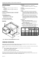
Dimensions:
Refer to Fig. 1.
Approvals:
Underwriters Laboratories Inc.: Listing 42U8.
Canadian Underwriters Laboratories Inc.: Listing 42U8.
Standard:
Air Conditioning and Refrigeration Institute Tested:
Standard 610
Models:
HE420A TRADELINE® and HE460A TRADELINE®
Steam Power Humidifier package includes mounting
template and hardware, H908A Humidity Control,
HC40 Automatic Flushing Timer with chlorine removal
filter.
HE420B TRADELINE® and HE460B TRADELINE®
Steam Power Humidifier package includes mounting
template and hardware, H1008A Automatic Humidity
Control, HC40 Automatic Flushing Timer with chlorine
removal filter.
Accessories:
C7089H Outdoor Temperature Sensor.
H1008A Automatic Humidity Control with HumidiCalc™
Software (software calculates dewpoint to prevent
moisture condensation).
H908A Convertible Humidity Control.
HumidiCalc™ Humidifier Sizing Software (software
calculates required humidifier capacity for application).
PC8900 Perfect Climate Comfort Center™ Control.
Table 1. Size Of Area That Can Be Humidified.
11-7/8 (302)
6 (152)
9 (229)
7-5/8 (194)
12-5/8 (321)
12-1/2 (318)
M10534A
HUMIDIFIER
HUMIDIFICATEUR
Fig. 1. Dimensions of HE420A,B/HE460A,B in in. (mm).
HE420 Area
(Up To)
HE460 Area
(Up To)
House
Description
Air
Changes
Per Hour Sq. ft Sq. m Sq. ft Sq. m
Loose Two 1,415 131 1,845 171
Average One 1,970 183 2,575 239
Tight One-half 3,095 288 4,045 376

HE420A,B AND HE460A,B STEAM POWER HUMIDIFIERS
68-0192—23
INSTALLATION
IMPORTANT
Read all the installation instructions before installing
the humidifier.
Select Location and Mount
There are three typical ways of mounting the steam
humidifier:
• horizontally under at least a 10 in. (254 mm) wide duct
using the mounting bracket (preferred mounting);
• horizontally under a reinforced duct;
• horizontally under a duct extension using the mounting
bracket.
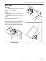
Decide which mounting is appropriate and follow those
mounting instructions. See Fig. 2 through 4.
Select a location where the humidifier can be plugged in
without an extension cord. The preferred installation location
is on the warm air side of the furnace. If that location is not
possible, mount the humidifier a minimum of 6 ft (1.8m)
upstream from the furnace filter. Depending on the location
selected, additional duct reinforcement may be necessary
because the humidifier weighs 18 lb when filled with water.
Fig. 3. Mounting humidifier horizontally under duct.
Fig. 2. Mounting humidifier horizontally under duct
using mounting bracket.
M10536A
HUMIDIFIER
HUMIDIFICATEUR
M10578A
HUMIDIFIER
HUMIDIFICATEUR
Fig. 4. Mounting humidifier horizontally under duct
extension using mounting bracket.
M10580A
HUMIDIFIER
HUMIDIFICATEUR

HE420A,B AND HE460A,B STEAM POWER HUMIDIFIERS
68-0192—2 4
M10876
TEMPLATE
1/2 IN. (13 MM)
FROM EDGE
WARNING
Electrocution, Heavy Equipment and Chemical
Hazard.
Can cause death, blindness, water damage to
home and heater failure.
• Do not cut into any air conditioning or electrical
line.
• Mount the humidifier in a level position to avoid
water damage and heater failure.
• Wear safety glasses when cutting or drilling.
• Reinforce duct as necessary to ensure stability.
CAUTION
Steam Condensation, Fire and Freezing Water
Hazard.
Can cause failure of fan or limit control or result
in water damage to home.
• Do not install the humidifier where the sidewalls
of the return air duct are constructed of wood
(i.e., floor joist).
• Do not install the humidifier where the
temperature is lower than 32°F (0°C) or higher
than 200°F (93°C).
Mount Horizontally Using Mounting Bracket
(Preferred Mounting Method)
IMPORTANT
The duct must be at least 10 in. (254 mm) wide to
use this mounting method.
The duct is the strongest when using the bracket mounting
method because the least amount of duct reinforcement is
required because of the bracket location. However,
reinforcement may still be necessary to help support the
weight of the humidifier and keep it level.
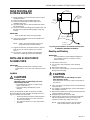
1. Tape the template 1/2 in. (13 mm) from the edge of the
duct and trace around the template. See Fig. 5.
2. Drill a 3/8 in. (10 mm) hole within the center portion of
the template.
3. Use tin snips to cut around the outline of the template.
IMPORTANT
Follow the dotted line carefully.
4. Remove the template and sheet metal.
5. Cut two 8 in. (203 mm) pieces of the S-cleat
(provided).
6. Place the S-cleat pieces on the narrow sides of the
rectangular opening so the opening (slot) protrudes
down and out of the duct.
Fig. 5. Position template.
7. Cut a 10-1/2 in. (267 mm) piece of S-cleat.
8. Place the 10-1/2 in. (267 mm) piece of S-cleat on the
long side of the rectangular opening closest to the
center of the duct so the opening (slot) shows below
the duct.
9. Use two 8-32 screws and nuts (provided) to attach the
mounting bracket (L shaped with six holes) to the top/
front surface of the humidifier. The humidifier is now
ready for mounting.
NOTE: Position the humidifier so the upward
protrusion of the U is on the side toward the
reservoir.
IMPORTANT
Do not mount the humidifier until the water level is
adjusted. See Set The Water Level section.
10. Slide the humidifier tabs into the installed S-cleat. Be
sure the back tab engages completely with the S-cleat
and the mounting bracket touches the side of the duct.
11. Using the mounting bracket as a guide, drill three
7/64 in. (3 mm) holes through the duct.
12. Secure the humidifier to the duct with three of the
no. 8 sheet metal screws (provided).

HE420A,B AND HE460A,B STEAM POWER HUMIDIFIERS
68-0192—25
Mount Horizontally on Reinforced Duct
This horizontal mounting method usually requires duct
reinforcement to support the weight of the humidifier and
keep it level. See Fig. 3. The mounting bracket is not used.
1. Tape the template to the bottom of the duct in the
desired location.
2. Drill a 3/8 in. hole (10 mm) within the center portion of
the shaded area.
3. Use tin snips to cut around the outline of the template.
IMPORTANT
Follow the dotted line carefully.
4. Remove the template and sheet metal.
5. Cut two 8 in. (203 mm) pieces of the S-cleat
(provided).
6. Place the S-cleat pieces on the narrow sides of the
rectangular opening so the opening (slot) protrudes
down and out of the duct.
7. Cut a 10-1/2 in. piece of S-cleat.
8. Place the 10-1/2 in. (267 mm) piece of S-cleat on the
long side of the rectangular opening, opposite the two
holes previously drilled. Position so the opening (slot)
protrudes down and out of the duct.
IMPORTANT
Do not mount the humidifier until the water level is
adjusted. See the Set The Water Level section.
9. Slide the humidifier tabs into the installed S-cleat. Be
sure the back tab engages completely with the S-cleat.
10. Secure the humidifier to the duct with two no. 8 sheet
metal screws (provided).
Mount Horizontally on Vertical Duct
Horizontal mounting on a vertical duct requires the
installation of a duct extension. See Fig. 4. Additional duct
reinforcement may also be necessary to help support the
weight of the humidifier and keep it level.
Create and install the duct extension. Then follow steps 1
through 12 in the Mount Horizontally Using Mounting Bracket
section to complete installation.
WIRING
All wiring must comply with local codes and ordinances.
When selecting a location for mounting the humidifier, be
sure connections can be made to the power source without
using an extension cord.
WARNING
Voltage or Fire Hazard.
Can Cause Death or Fire.
Use a receptacle rated at 120 Vac, 15/20A (NEMA
configuration 5-15R) for the HE420A,B Humidifiers.
Use a receptacle rated at 240 Vac, 15/20A (NEMA
configuration 5-15R) for the HE460A,B Humidifiers.
Air Mover Applications
CAUTION
Moisture Condensation and Wiring Hazard.
Moisture can destroy furnace electronic controls
and miswiring can burn out electrical
components.
• Do not alter any of the heating and cooling
system functions.
• Be sure to wire only the system fan.
Refer to the wiring diagrams in Fig. 6 through 8 for typical air
mover applications.
Fig. 6. Typical wiring diagram for humidifier in single-
speed air mover applications without air conditioning
(switching through external relay).
L2
1
3
1
1
2
3
2
BLACK
BLACK
FAN
WIRING
WHITE
WHITE
HUMIDISTAT
TERMINALS
TO
HUMIDISTAT
COMPRESSOR
Y CONTACTOR
STEAM HUMIDIFIER
G CONTACTOR
FAN LIMIT CONTROL
K
K
K
COOL
HEAT
HIGH
SPEED
LOW
SPEED
AIR MOVER/
EQUIPMENT
BLOWER
L2
(HOT)
L1
M10874
24V WIRING.
EXTERNAL RELAY NOT SUPPLIED.
FOLLOW THE INSTALLATION INSTRUCTIONS INCLUDED
WITH THE HUMIDISTAT.
TO
TRANSFORMER
(NOT SUPPLIED)
Fig. 7. Typical wiring diagram for humidifier in dual-
speed air mover applications with air conditioning.
L1
L2
1
1
2
3
1
2
3
FAN LIMIT CONTROL
AIR MOVER/
EQUIPMENT
BLOWER
STEAM HUMIDIFIER
THERMAL
SWITCH
FAN WIRING
HUMIDISTAT
TERMINALS
TO
HUMIDISTAT
WHITE
BLACK
BLACK
24V WIRING.
EXTERNAL RELAY NOT SUPPLIED.
FOLLOW THE INSTALLATION INSTRUCTIONS INCLUDED
WITH THE HUMIDISTAT.
M10873
(HOT)
WHITE
TO TRANSFORMER
(NOT SUPPLIED)

HE420A,B AND HE460A,B STEAM POWER HUMIDIFIERS
68-0192—2 6
Fig. 8. Typical wiring diagram for humidifier in single-
speed air mover applications without air conditioning
(switching through G contactor).
The humidifier has a sealed switch with a thermostatic
sensor that is designed only for pilot duty (low voltage)
applications. The sealed switch is attached to the humidifier
wall. The switch is preset to turn on the fan when the water
temperature is 170°F (77°C) and turn off the fan when the
water temperature falls below 120°F (49°C).
IMPORTANT
The Honeywell S688A Fan Sail Switch must be
installed if the system fan is on continuously.
Heat Pumps
No wiring diagrams can be suggested due to the many
variations and wiring complexity of heat pumps. If the
humidifier control fan operation is desired, be sure to design
a safe control circuit using equipment diagrams and tracing
the equipment wiring.
In heat pump installations, a fan sail switch must be installed
due to the almost continuous operation of the system fan.
Wire the fan sail switch in series with the low voltage
humidity control circuit so the humidifier is on only when the
fan is operating; however, the humidifier, in most cases, does
operate in conjunction with the system fan.
PLUMBING HUMIDIFIER
CAUTION
Chemical Hazard.
Can cause damage to environment or air
conditioning system.
Do not use any refrigerant line connected to an air
conditioner.
Be sure to install the chlorine removal filter (provided)
to prevent humidifier corrosion.
Either hard or soft water can be used in the humidifier.
IMPORTANT
Use only copper tubing to plumb the humidifier.
1. Locate the cold water pipe closest to the humidifier.
2. Install the saddle valve connector.
3. Use the valve instructions to install the valve
(provided). The valve is self-piercing when installed on
copper pipe.
IMPORTANT
Position the valve so water flows from the top or
side to reduce the chance of clogging the valve with
minerals.
Lightly clean the copper tubing ends with fine
sandpaper before making any connections.
4. Install the chlorine removal filter.
5. Place the brass compression nut over the copper
tubing.
6. Slide the brass ferrule over the tubing.
NOTE: Do not overtighten the compression nut.
Moderate tightness prevents leaking.
7. Insert the tubing into the valve fitting and tighten the
compression nut.
8. Flush the copper tubing to remove any debris that can
cause problems at the float valve.
SET WATER LEVEL
Adjust the humidifier water level prior to mounting.
1. Set the humidifier reservoir on a level surface.
2. Attach the water feed line and allow the unit to fill until
the float valve shuts off the incoming flow of water. The
water level should be between 2-1/4 in. (57 mm) and
2-1/2 in. (64 mm) deep. If water level is correct, go to
step 4.
3. Adjust the water level in small increments. Raise the
water level by pushing down on the center of the float
arm. Lower the water level by pressing the float down
with one hand and pulling up on the center of the float
arm with the other hand. See Fig. 9.
CAUTION
Flooding Hazard.
Inadequate support of the float arm can lead to
valve seat damage and result in water leakage.
Support the float arm during adjustment.
L1
L2
1
1
2
1
G CONTACTOR
AIR MOVER/
EQUIPMENT
BLOWER
HUMIDISTAT
TERMINALS
WHITE
BLACK
WHITE
BLACK
24V WIRING.
FOLLOW THE INSTALLATION INSTRUCTIONS INCLUDED
WITH THE HUMIDISTAT.
M10875
2
STEAM HUMIDIFIER
FAN WIRING
TO
HUMIDISTAT
(HOT)
RC
G
Z
Fig. 9. Adjust water level.
4. Verify the water level by removing enough water to
allow the float valve to automatically fill and shut off
the water.
TO RAISE WATER LEVEL
PUSH
DOWN
TO LOWER WATER LEVEL
HOLD
DOWN
PUSH
UP
M10581

HE420A,B AND HE460A,B STEAM POWER HUMIDIFIERS
68-0192—27
FINISH MOUNTING AND
PLUMBING HUMIDIFIER
1. Mount humidifier as instructed in the Select Location
and Mount section.
2. Route the tubing to the humidifier float valve
.
3. Connect the remaining end of the tubing to the
humidifier float valve.
4. Open the saddle valve so that the water flows slowly
into the water pan.
5. Check the compression fittings at the saddle valve and
the float valve. Tighten the fitting slightly to stop any
leakage.
IMPORTANT
Keep all drain lines away from sharp edges.
6. Connect the overflow provision of the humidifier to a
suitable waste drain.
NOTE: A 5/8 in. (16 mm) ID garden hose can be
easily attached to the overflow fitting.
7. Support the drain line at several locations to prevent
kinks. Be sure to provide support near any heat
source.
8. Use a male 1-1/2 in. NPT fitting (not supplied) to
connect the overflow provision of the humidifier.
INSTALLING HC40 AUTOMATIC
FLUSHING TIMER
IMPORTANT
All plumbing and electrical connections must
comply with all local codes and ordinances for the
area.
Location
CAUTION
Flooding Hazard.
Improper location of drain tubing can cause
water damage to home.
• Drain tubing must not kink or contact sharp
edges or hot surfaces.
• Slope drain tubing downward for correct
drainage.
Choose an appropriate location for the timer mounting
before installing the HC40 Automatic Flushing Timer. See
Fig. 10. The timer must be located:
• Near waste drain for disposal of flushing water.
• At a maximum distance of 5 ft (1.5m) from a
fused electrical outlet.
• At a maximum distance of 3 ft (0.9m) from the
humidifier.
Fig. 10. Typical installation of automatic flushing timer
on HE420A,B, HE460A,B Humidifiers.
Mounting and Plumbing
IMPORTANT
Some installations require additional fittings. Be
sure all fittings are brass or stainless steel to
prevent corrosion.
1. Remove the timer cover.
2. Use screws to attach the timer to the mounting
surface.
3. Replace the timer cover.
4. Cut a piece of drain tubing to connect the humidifier
fitting to the timer fitting.
CAUTION
Flooding Hazard.
Improper location of drain tubing can cause
water damage to home.
Drain tubing must not kink or contact sharp edges or
hot surfaces.
5. Cut a second piece of tubing to reach from the flushing
unit to the drain.
6. Use clamps or suitable fittings to connect the tubing to
the humidifier and drain.
7. Return the humidifier to its normal operating mode and
properly adjust the water level.
8. Plug the timer into the electrical outlet.
9. Verify the timer operation by activating the humidifier
with an appropriately sized coin. Turn the plastic
indicator clockwise very slowly. See Fig. 11.
NOTE: This activates the drain valve and allows
water to flow from the unit to the drain.
M10587
DRAIN
FITTING
STEAM
HUMIDIFIER
CLAMPS (2)
DRAIN TUBING
PLUMB TO
WASTE DRAIN
HC40
AUTOMATIC
FLUSHING
TIMER
CLAMP

HE420A,B AND HE460A,B STEAM POWER HUMIDIFIERS
68-0192—2 8
temperature setting scale on your humidity control. Match
the dial setting to the outdoor temperature to optimize the
humidity level while reducing the moisture condensation on
your windows. Use Table 2 to adjust the humidity control to
the recommended setting.
NOTE: As the outside temperature drops, lower the
recommended setting to accommodate the effects
of dewpoint. These settings should reduce the
accumulation of moisture and ice on the windows
and in other areas of the house.
Some indoor activities such as cooking, showering and
clothes drying can cause excessive levels of humidity and
start the accumulation of moisture on the windows.
NOTE: If this condition persists for more than a few hours,
set the humidity control to the lowest setting to turn
off the humidifier. If the condition does not improve,
ventilate the house to remove the moisture.
Your Honeywell HE420B and
HE460B Humidifiers are
controlled by the Honeywell
H1008 Automatic Humidity
Control with HumidiCalc
Software. The automatic
humidity control is mounted in
the return air duct where it can
be exposed to the air stream of
the return air. The HumidiCalc
Software inside your automatic
humidity control is designed to
automatically adjust the
humidity level based on indoor temperature and humidity,
inferred or measured outdoor temperature, and the setting of
the frost factor dial. The frost factor allows for variations in
furnace size, window insulation and average daily climate
temperature.
The Automatic Humidity Control with HumidiCalc Software
requires an initial adjustment period. Set the frost factor dial
on 5 and use Table 3 to adjust the frost factor–only one
setting at a time–increasing the dial setting if you feel you
need more humidity, or reducing the setting if you see
moisture on the inside of your windows. For more precise
humidity adjustment, set the frost factor between dial
settings. Allow two days for the humidity level to subside
before making further adjustments. Once you have tuned in
the proper setting, you should not have to further adjust it
again. HumidiCalc™ Software takes over and makes any
future adjustments caused by varying outdoor temperatures,
thus reducing moisture buildup on windows while
maintaining the optimal humidity level.
Fig. 11. Turn plastic indicator on timer side.
10. Check all fittings for leaks; tighten if necessary.
11. Allow the timer to run for one complete cycle
(7-1/2 minutes). This assures that proper cycle time
was obtained.
NOTE: Complete the installation before activating the
timer. Some vibrating noise occurs when
there is no water. The noise stops when water
is present.
CHECKING THE INSTALLATION
After installation is complete, use the following procedure to
check the humidifier operation:
1. Turn on the humidifier water supply.
2. Be sure the humidifier has power and plug in the
humidifier.
3. Turn the Convertible Humidity Control to the highest
setting, or the H1008 Automatic Humidity Control to
the Test position.
4. Check that the furnace blower comes on to circulate
the moist air. The blower may take as long as fifteen
minutes to turn on.
5. Reset the Convertible Humidity Control to a
comfortable setting, or the Automatic Humidity Control
to the desired frost factor setting for automatic
operation.
OPERATING THE HUMIDIFIER
The HE420A and HE460A
Humidifiers are controlled by
the Convertible Humidity
Control that is installed either
on the interior wall in the living
area or on the return air duct.
Choose the humidity control
setting using the combination
relative humidity/outdoor
TURN CLOCKWISE VERY SLOWLY
SLOT FOR COIN
COIN
M10552
At Outside Temperature Recommended Setting At Outside Temperature Recommended Setting
-20°F (-29°C) 15 +10°F (-12°C) 30
-10°F (-23°C) 20 +20°F (-7°C) 35
0°F (-18°C) 25 Above 20°F (-7°C) 40
Table 2. Recommended Convertible Humidity Control Settings.
M13155
H908A
M12817
H1008A

HE420A,B AND HE460A,B STEAM POWER HUMIDIFIERS
68-0192—29
Table 3. Recommended Frost Factor Settings.
Humidity Level Recommended Adjustment
Insufficient
humidity
Increase the frost factor dial by
one setting.
Condensation on
windows
Decrease the frost factor dial by
one setting.
OPERATION
The HE420A,B and HE460A,B Humidifiers use the principle
that hot water creates water vapor. As dry air and vapor mix,
the relative humidity of the air rises. The humidity control
monitors the relative humidity and activates the humidifier
accordingly.
When the humidity control calls for humidity, the humidifier
underwater heater starts heating the water in the humidifier
reservoir. When the water is warm enough, the humidifier
activates a relay that turns on the furnace fan. The warm dry
air from the furnace picks up the water vapor and circulates
it through the home. The fan continues to circulate the air
until the water cools down and then turns off the fan.
Humidified air feels warmer and more comfortable so you
may be able to lower the thermostat heating setpoint and
save money on heating fuel bills giving you a more
comfortable environment that is also energy efficient.
MAINTENANCE
A regular maintenance program prolongs the life of the
humidifier and provides a more comfortable environment.
Frequency of cleanings depends on water conditions. Either
hard or soft water can be used in the humidifier, but hard
water mineral deposits are more difficult to clean.
CAUTION
Voltage Hazard.
Can cause electrical shock and equipment
damage.
Disconnect power supply before installing or
servicing.
IMPORTANT
Never oil any part of the humidifier.
Every 1 to 4 Months
(Depending on Water Quality)
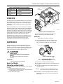
Use the following procedure and refer to Fig. 12 to clean the
humidifier:
1. Unplug the humidifier and fan control.
2. Disconnect the humidity control wires from the external
screw terminals on the humidifier.
3. Turn off the water supply.
Fig. 12. Location of humidifier parts.
4. Disconnect water feed tubing at the float valve.
5. Disconnect the overflow at the humidifier.
IMPORTANT
Allow water to cool before continuing.
6. Use an appropriate coin and very slowly turn the
automatic flushing timer indicator clockwise. See
Fig. 13. Allow the humidifier to drain completely.
M12310B
Honeywell Humidifier Model HE460
For Residential Use Only
240 Volts, 1 Phase, 60 Hz, 1500 Watts
Danger: Possible electric shock and burn.
Disconnect electrical supply and let water cool
before servicing or cleaning.
Honeywell, Inc. 1885 Douglas Drive. Minneapolis, MN 55422-3992
R
Listed 42U8
R
Listed 42U8
SAFETY
FLOATSWITCH
HEATER
FLOAT
RESERVOIR
VALVE ARM
HUMIDITY
CONTROLS
Fig. 13. Turn automatic flushing timer
indicator clockwise.
7. Remove the humidifier from the mounting.
8. Use running tap water to flush loose minerals from the
reservoir.
9. Carefully rub off minerals from the float, heater and
safety float switch.
NOTE: Steel wool or other scouring pads can be
used on the reservoir walls and other parts.
10. Remove the valve arm by pulling out the center pin
attachment. Inspect the arm for mineral buildup and
deterioration.
TURN CLOCKWISE VERY SLOWLY
SLOT FOR COIN
COIN
M10552

HE420A,B AND HE460A,B STEAM POWER HUMIDIFIERS
68-0192—2 10
IMPORTANT
• Replace the float valve when it shows any signs of
deterioration.
• The float valve should shut off the water at 2-3/8 in.
(60 mm).
11. Reset the water level:
CAUTION
Flooding Hazard.
Inadequate support of the float arm can lead to
valve seat damage resulting in water leakage.
Support the float arm during adjustment.
a. Set the humidifier reservoir on a level surface.
b. Attach the water feed line and allow the unit to fill
until the float valve shuts off the incoming flow of
water. The water level should be between
2-1/4 in. (57 mm) and 2-1/2 in. (64 mm) deep. If
water level is correct, go to step d.
c. Adjust the water level in small increments. Raise
the water level by pushing down on the center of
the float arm. Lower the water level by pressing
the float down with one hand and pulling up on
the center of the float arm with the other hand.
See Fig. 9.
d. Verify the water level by removing enough water
to allow the float valve to automatically fill and
shut off the water.
12. Remount the humidifier.
13. Reconnect all plumbing connections.
14. Reconnect all electrical connections.
15. Verify humidifier operation by following the steps in the
Checkout Procedures section.
End of Humidification Season
Clean and shut off the humidifier at the end of the heating
season. Use the Every 1 To 4 Months section, steps 1
through 14, to shut down for the season.
IMPORTANT
Be sure the humidifier power is off and there is no
water in the humidifier.
Vacation
When you leave on vacation, turn off the humidifier water
supply and the humidity control. When you return, turn on
the humidifier water supply and reset the humidity control to
restart the humidifier.
CHECKOUT PROCEDURES
After winter start-up or maintenance, use the following
procedure to check humidifier operation:
1. Turn on the humidifier water supply.
2. Be sure the humidifier has power and plug in the
humidifier.
3. Turn the Convertible Humidity Control to the highest
setting, or the H1008 Automatic Humidity Control to
the Test position.
NOTE: The H1008A Automatic Humidity control stays in
the test mode for thirty minutes. After thirty minutes,
the control automatically resets to the maximum
frost factor setting. If system checkout was not
completed in thirty minutes, extend the test mode
by turning the dial back to one of the dial settings
and then returning it to the test mode.
4. Check that the furnace blower turns on to circulate the
moist air. The blower may take as long as fifteen
minutes to turn on.
5. Reset the Convertible Humidity Control to a
comfortable setting, and the Automatic Humidity
Control to the desired frost factor setting for automatic
operation.
Problem What To Look For What To Do
Low humidity Furnace blower not operating. • Reset circuit breaker or check for blown
fuse.
• Check that the furnace power is on.
• Check all external wiring connections.
• Check the humidity control setting.
• Call a professional heating contractor.
Rapid air changes. Drafts (cold air
is dry and is an added load for the
humidifier).
• Keep doors and windows closed.
• Close fireplace damper when not in use.
• Keep exhaust fan running time to a minimum.
• Seal around doors and windows.
High humidity Condensation on walls. • Turn off humidity control and water until
condensation is completely evaporated.
Heavy condensation on windows. • Turn humidity control down low enough to
eliminate condensation caused by moisture
from bathing, mopping, cooking, etc. If
moisture persists, more ventilation is needed.
TROUBLESHOOTING
Refer to Table 4 for troubleshooting procedures.
Table. 4. Troubleshooting Procedures.

HE420A,B AND HE460A,B STEAM POWER HUMIDIFIERS
68-0192—211
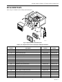
REPLACEMENT PARTS
Refer to Fig. 14 and Table 5 when ordering replacement parts.
Fig. 14. Exploded view of humidifier parts.
Table 5. List of Replacement Parts for HE420A,B, HE460A,B Humidifiers.
M12238B
4
2
3
1
5
8
9
15
16
17
6
11
13
7
14
10
12
Honeywell Humidifier Model HE460
For Residential Use Only
240 Volts, 1 Phase, 60 Hz, 1500 W
atts
Danger: Possible electric shock and burn.
Disconnect electrical supply and let water cool
before servicing or cleaning.
Honeywell, Inc.
1885 Douglas Drive. Minneapolis, MN 55422-3992
R
Listed 42U8
R
Listed 42U8
Exploded View
Number Description
HE420 Part
Number
HE460 Part
Number
1 Incoloy® sheathed heating element 32000164-001 32000148-001
2 Safety float switch 32000149-001 32000149-001
3 Float for water fill valve 32000166-001 32000166-001
4 Water fill valve 32000167-001 32000167-001
5 Water pan assembly 32000152-001 32000152-001
6 Electrical enclosure cover 32000169-001 32000153-001
7 Transformer, 24 Vac AT120B1010 AT120B1069
8 Control relay, dpst, 24 Vac R8222C1008 R82222C1008
9 Fan wiring assembly 32000156-001 32000156-001
10 Humidistat control terminal block 32000157-001 32000157-001
11 Indicator light 32000158-001 32000158-001
12 Thermal fan switch 32000159-001 32000159-001
13 Power distribution block 32000160-001 32000160-001
14 Power supply cord with strain relief 32000177-001 32000161-001
15 Saddle valve assembly 32001616-001 32001616-001
16 Convertible Humidity Control H908A1003 H908A1003
17 Automatic Humidity Control H1008A1008 H1008A1008
— Automatic Fushing Timer HC40A1009 HC40A1009

Honeywell Europe S.A.
3 Avenue du Bourget
1140 Brussels
Belgium
Honeywell Asia Pacific Inc.
Room 3213-3225
Sun Hung Kai Centre
No. 30 Harbour Road
Wanchai
Hong Kong
Home and Building Control
Honeywell Limited-Honeywell Limitée
155 Gordon Baker Road
North York, Ontario
M2H 3N7
Honeywell Latin American Region
480 Sawgrass Corporate Parkway
Suite 200
Sunrise FL 33325
68-0192—2 J.S. Rev. 6-98
Home and Building Control
Honeywell Inc.
Honeywell Plaza
P.O. Box 524
Minneapolis MN 55408-0524
Printed in U.S.A. on recycled
paper containing at least 10%
post-consumer paper fibers.
www.honeywell.com
-
 1
1
-
 2
2
-
 3
3
-
 4
4
-
 5
5
-
 6
6
-
 7
7
-
 8
8
-
 9
9
-
 10
10
-
 11
11
-
 12
12


Honeywell HE420B1007 Owner's manual
- Category
- Dehumidifiers
- Type
- Owner's manual
- This manual is also suitable for
Ask a question and I''ll find the answer in the document
Finding information in a document is now easier with AI
Related papers
-
Honeywell HE480A1006 Owner's manual
-
-
Honeywell HE420B User manual
-
-
-
Honeywell HE120 User manual
-
-
Honeywell HE260 User manual
-
-
Other documents
-
 Skuttle Indoor Air Quality Products SK0-0055-001 User manual
-
Hamilton M-300 Owner's manual
-
 Herrmidifier 707U-UK User manual
-
 Herrmidifier 707U-UK User manual
-
 AutoFlo X-15A Owner's manual
-
 Honeywell Home HE280D2001/U User guide
-
Trion 259941-001 Owner's manual
-
Philips HU4804/41 User manual
-
White Rodgers HSP2000 Owner's manual
-


