American Power Conversion SUDP10000I User manual
- Type
- User manual

990-1007A, Revision 2 9/99
Smart-UPS DP
Uninterruptible Power Supply
Models
SUDP4000I, SUDP6000I, SUDP8000I, SUDP10000I
User’s Manual

Entire contents copyright ©1999 by American Power Conversion. All rights reserved. Reproduction in whole or in part
without permission is prohibited. Smart-UPS is a registered trademark of APC. All other trademarks are the property of
their respective owners.
990-1007A, Revision 2 9/99

990-1007A, Revision 2 9/99
Smart-UPS DP Quick Reference Guide English
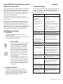
About Your New UPS
This Uninterruptible Power Supply (UPS) prevents blackouts,
brownouts, sags and surges from reaching your computer and
other valuable electronic equipment, filters out utility line
fluctuations, and isolates your equipment from disturbances by
actively controlling voltage to loads, and supplying power
from its batteries when required.
While running on battery, an internal alarm will sound
(periodic beeps). The mute button may be pressed to silence
the UPS alarm.
If the utility power does not return, the UPS will continue
supplying power to the connected equipment until exhausted.
A continuous beeping will sound two minutes before the
UPS’s final low battery shutdown. If using a computer, you
must manually save your files and power down before the UPS
turns itself off, unless you are using PowerChute interface
software that provides automatic, unattended shutdown.
Installation and Setup
1. Install UPS
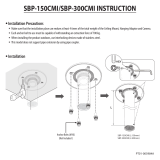
• The Smart-UPS DP must be installed by a local
authorized electrician.
• National and local electrical regulations must be adhered
to during installation and operation.
F
0
0
1
M
a
i
n
s
2. Turn on UPS
• Switch on the mains fuse on the rear of the
UPS. The Smart-UPS DP will perform a
self-check ending with the LED display
showing red/yellow/green, indicating the
unit is functioning properly. The unit
performs a self-test automatically when
turned on, and every two weeks thereafter.
• Turn the on/off switch on the front of the
Smart-UPS DP to 1 (up). The acoustic
alarm will give a short beep when output
power is available.
• The UPS charges its battery whenever it is
connected to utility power and the on/off
switch on the front of the unit is turned on
(1 or up). The battery charges fully during
the first 4 hours of normal operation. Do
not expect full runtime during this initial
charge period.
3. Install PowerChute
®
• For additional computer system security, install
PowerChute
®
UPS monitoring software. It provides
automatic unattended shutdown capabilities on most
major network operating systems. See the Software
Installation: Instruction Sheet for details.
Troubleshooting
Use the chart below to solve minor UPS installation problems.
Contact APC Technical Support Staff for assistance with
complex UPS problems. See APC Contact Information, page
18, for a location near you.
Problem and
Possible Cause
Solution
UPS will not turn on.
• On/off switch turned to off
(0 or down).
Turn the switch to 1 (up) to power the UPS
and the load.
• Fuse switch turned to off
(down).
Turn the switch up.
• On/off switch needs to be
cycled on and off
Switching the on/off switch to off (0 or
down) and on again (1 or up).
• UPS not connected to AC
power supply.
Check that the power cable from the UPS to
the power supply is securely connected at
both ends.
• UPS input circuit breaker
tripped.
Reduce the load on the UPS by unplugging
equipment and reset the fuse switch (on
back of UPS) by switching it up.
• Very low or no utility
voltage.
Check the circuit breakers to the AC power
supply.
UPS will not turn off.
• Internal UPS fault.
Have the UPS serviced immediately.
UPS operates on-battery although normal line voltage exists.
• UPS input circuit breaker
tripped.
Reduce the load on the UPS by unplugging
equipment and reset the fuse switch (on
back of UPS) by switching it up if
necessary.
• Very high, low, or distorted
line voltage. Inexpensive
fuel powered generators can
distort the voltage.
Move the UPS to a different circuit.
Test the input voltage using PowerChute.
UPS beeps occasionally.
• Normal UPS operation.
None. The UPS is protecting the load.
UPS does not provide expected backup time.
• The UPS’s battery is weak
due to recent outage or is
near the end of its service
life.
Charge the battery. Batteries require
recharging after extended outages. Also,
they wear faster when put into service often
or when operated at elevated temperatures.
If the battery is near the end of its service
life, consider replacing the battery.
• The UPS is overloaded.
Check the UPS’s load using PowerChute.
Unplug less needed equipment, such as
printers.
Front panel indicators off.
• The UPS has been shut
down by remote control.
None. The UPS will restart automatically
when utility power returns.
All indicators are lit constant red and UPS emits a constant beeping.
• Overload
Reduce the load on the UPS by unplugging
equipment and reset the fuse switch (on
back of UPS) by switching it up if
necessary.
• Internal UPS fault.
Have the UPS serviced immediately.
All indicators are off and UPS is connected to the AC power.
• The UPS is shut down and
the battery is discharged
from an extended outage.
None. The UPS will return to normal
operation when the power is restored and
the battery has a sufficient charge.
All indicators are flashing yellow.
• Weak batteries.
Do another self test to see if it clears
• Replacement batteries not
connected properly.
Confirm the battery connections.


990-1007A, Revision 2 9/99
i
Table of Contents
Safety .........................................................................................................................................................................................................1
Handling Safety......................................................................................................................................................................................1
Electrical Safety .....................................................................................................................................................................................1
Deenergizing Safety ...............................................................................................................................................................................1
Battery Safety.........................................................................................................................................................................................1
Replacement and Recycling of Batteries ................................................................................................................................................1
Initial Inspection.......................................................................................................................................................................................2
Inspection ...............................................................................................................................................................................................2
Unpacking ..............................................................................................................................................................................................2
Placement ...............................................................................................................................................................................................3
Installation Instructions...........................................................................................................................................................................3
Checking Electrical Data........................................................................................................................................................................3
Electrical Connections............................................................................................................................................................................3
Mains Connections .................................................................................................................................................................................4
Rear Views .............................................................................................................................................................................................5
Common Fault........................................................................................................................................................................................6
Computer Interface Port (Optional)........................................................................................................................................................6
Emergency Power Off (EPO) Remote Shut Down and Signal Relay Port (Optional)............................................................................6
Optional Equipment Installation ............................................................................................................................................................8
Galvanic Isolation Transformer..............................................................................................................................................................8
External Service Bypass Panel (SBP) ..................................................................................................................................................10
External Service Bypass Panel and Galvanic Isolation Transformer....................................................................................................11
External Run Battery Cabinet...............................................................................................................................................................12
Operating Instructions...........................................................................................................................................................................13
Switching On ........................................................................................................................................................................................13
Switching Off .......................................................................................................................................................................................13
Setting the Voltage ...............................................................................................................................................................................13
External Service Bypass Panel Operation ............................................................................................................................................13
LEDs ....................................................................................................................................................................................................14
Batteries ..................................................................................................................................................................................................15
Automatic Battery Check .....................................................................................................................................................................15
Manual Battery Check..........................................................................................................................................................................15
Battery Replacement ............................................................................................................................................................................15
Storage.....................................................................................................................................................................................................15
Storage Conditions ...............................................................................................................................................................................15
Extended storage ..................................................................................................................................................................................15
Service .....................................................................................................................................................................................................15
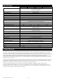
Specifications ..........................................................................................................................................................................................16
Limited Warranty ..................................................................................................................................................................................16
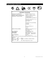
Regulatory Agency Approvals ..............................................................................................................................................................17
APC Contact Information .....................................................................................................................................................................18
Latin America, South America .............................................................................................................................................................18
Europe, Middle East, Africa.................................................................................................................................................................18
Asia, Australia......................................................................................................................................................................................18

990-1007A, Revision 2 9/99

990-1007A, Revision 2 9/99
1
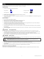
Safety
This Safety Guide contains important instructions that should be followed during installation and maintenance of the APC equipment and batteries.
It is intended for APC customers who setup, install, relocate, or maintain APC equipment.
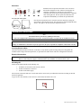
Handling Safety
• Be careful. Do not lift heavy loads without assistance.
<18 kg (<40 lb.)
18-32 kg (40-70 lb.)
32-55 kg (70-120 lb.)
>55 kg (>120 lb.)
• Equipment with casters is built to move on a smooth surface without any obstacles.
• Do not use a ramp inclined at more than 10°.
• This equipment is intended for installation in a temperature-controlled indoor area (see the User's Manual for exact temperature range), free of
conductive contaminants.
Electrical Safety
• Do not work alone under hazardous conditions.
• High short circuit current through conductive materials could cause severe burns.
• A licensed electrician is required to install permanently wired equipment.
• Check that the power cord(s), plug(s), and sockets are in good condition.
• To reduce the risk of electric shock when grounding cannot be verified, disconnect the equipment from the AC power before installing or
connecting to other equipment. Reconnect only after all connections are made.
• Do not handle any kind of metallic connector before the power has been removed.
• Use one hand, whenever possible, to connect or disconnect signal cables to avoid a possible shock from touching two surfaces with different
electrical grounds.
• Connect the equipment to appropriate branch circuit/mains protection (fuse or circuit breaker). Connection to any other type of receptacle may
result in a shock hazard.
CAUTION!
Deenergizing Safety
• If the equipment has an internal energy source (the battery), the output may be energized when the unit is not connected to AC power.
• To deenergize permanently wired equipment: set the power switch to off (0 or down). Next set the AC circuit breaker to off (down). Then
disconnect the batteries (including any expansion units). Finally, disconnect the AC power from the building power supply.
• Use of this equipment in life support applications where failure of this equipment can reasonably be expected to cause the failure of the life
support equipment or to significantly effect its safety or effectiveness is not recommended.
WARNING!
Battery Safety
• This equipment contains potentially hazardous voltages. Do not attempt to disassemble the unit. The unit contains no user serviceable parts.
Repairs are performed only by factory trained service personnel.
Batteries must be recycled. Deliver the battery to an appropriate recycling facility or ship it to the supplier in the new
battery’s packing material. See the new battery instructions for more information.
• Do not dispose of batteries in a fire. The batteries may explode.
• Do not open or mutilate batteries. They contain an electrolyte which is toxic and harmful to the skin and eyes.
• To avoid personal injury due to energy hazard, remove wrist watches and jewelry such as rings when replacing the batteries. Use tools with
insulated handles.
• Replace batteries with the same number and type of batteries as originally installed in the equipment.
Replacement and Recycling of Batteries
See your dealer or the Battery Replacement Section of this User’s Manual for information on replacement battery kits and battery recycling.

990-1007A, Revision 2 9/99 2
Initial Inspection
Inspection
Inspect the UPS upon receipt. Notify the carrier and dealer if there is damage. The packaging is recyclable; save it for
reuse or dispose of it properly.
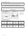
Unpacking
Move the UPS, in its shipping package, as close to the desired location as possible. Then follow these instructions:
Use scissors or a knife to cut the
plastic straps and open the
package.
Refer to this User’s Manual
for safety information and
installation instructions.
Unpack all visible foam pieces
and the wooden unloading
ramp.
Lift off the cardboard box that
covers the top and sides of the
package. A wooden pallet
forms the bottom of the box.
Remove the carton liner. Unscrew the hold-down bolts
that secure the Smart-UPS DP
to the pallet.
Pull out the two (2) metal bars
and set aside.
Open the literature kit and
locate the two (2) metal pallet
brackets.
Insert the metal pallet brackets
into the holes on the unloading
ramp.
Attach the unloading ramp to
the pallet.
Have two (2) people, standing
on either side of the Smart-UPS
DP, wheel the unit down the
unloading ramp. Do not stand
in front of the UPS.

990-1007A, Revision 2 9/99
3
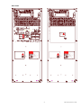
Placement
Sm a rt-U P S D P
Sm a rt-U P S D P
Sm a rt-U P S D P
Install the UPS in a protected area that is free of excessive
dust and has adequate air flow. Sufficient cooling must be
ensured by a minimum of 150 mm free space from the
ventilation slots on the back, and 200 mm from the ventilation
slots on the right side. Do not operate the UPS where the
temperature and humidity are outside the specified limits.
To secure the unit in place
Once the unit is positioned, use a wrench to lower the drop bolts, raising the
front wheels so the unit will not roll. The drop bolts are located behind the front
wheels. The figure to the left shows the drop bolts lowered.
Installation Instructions
Note:
This function must be performed by qualified personnel only.
This UPS is equipped with a SmartSlot for accessories. See the APC Website (www.apcc.com) for available accessories.
Warning!
Changes or modifications to this unit not expressly approved by the party responsible for compliance could void the warranty.
Checking Electrical Data
Check the identification label on the back of the unit to verify that the specified voltage and power rating match the
available mains voltage and load requirements, as specified in the tables shown with each configuration connection.
Electrical Connections
Warning!
Make sure that main power supply is switched off before any installation is carried out on the system.
Switching Off
Switch off the Smart-UPS DP in the following way:
1. Switch the on/off switch on the front to 0 (down).
2. Switch off mains fuse on the rear.
3. Switch off the mains supply.
The electrical connections and service on the unit must be carried out by an authorized electrician according to national
and local regulations.
To get access to the terminals, remove the screw on the back, and remove the cover.
DANG ER
HIGH VOLTAGE

990-1007A, Revision 2 9/99 4
External Connections
Notes:
As a standard, the Smart-UPS DP is made for single-phase connection.
Due to the leakage current of 3.5 to 10 mA, the Smart-UPS DP must always be grounded according to local regulations.
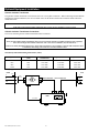
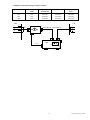
Mains Connections
Make these connections only if no optional equipment (see the Optional Equipment Installation, page 8) is being used.
Mains Fuses and Cable Dimensions
Standard System
System Mains Fuse * (Fm) Input Cable UPS Output Cable UPS
4kV 25A 3x6 mm² 3x4 mm²
6kV 40A 3x10 mm² 3x10 mm²
8kV 50A 3x16 mm² 3x10 mm²
10kV 63A 3x16 mm² 3x16 mm²
* Din gl Types
UPS
EPOCOM
PORT
NL NL +
LOAD
L
N
OUTPUT CABLE UPS
MAINS
L
N
PE
INPUT CABLE UPS
Fm

990-1007A, Revision 2 9/99
5
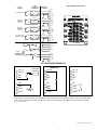
Rear Views
F
0
0
1
M
a
i
n
s
F
0
0
1
M
a
i
n
s
16)
15)14)
13)
12)
11)
10)
9)
8)
7)
6)5)
4)
3)
2)
1)
A DC
AH
MIN.:STORED ENERGY TIME
OU TPUT :
INPUT :
AH
V DC /
V /
2. REPLACEMENT
1. REPLACEMENT
INSTALLE D
YEARMONTH
REPLACEMENT OF BAT TERI ES
KG.WEIGHT:
S. NO. :
TYPE:
P.NO.:
RECORD THE DATE OF REPLACEMEN T.
EVERY 3 - 5 YEARS.
REPLACE BATTERIES AT LEAST
NOMINAL BATTERY CAPACITY
U/I BATTERY N ORMINAL
NO. OF BA TTERIES
TYPE OF BATTERIES
16)
15)14)
13)
12)
11)
10)
9)
8)
7)
6)5)
4)
3)
2)
1)
A
DC
AH
MIN.:STORED ENERGY TIME
OU TPUT :
INPUT :
AH
V DC /
V /
2. REPLACEMENT
1. REPLACEMENT
INSTALLED
YEARMONTH
REPLACEMENT OF BATTERIES
KG.WEIGHT:
S. NO.:
TYPE:
P.NO.:
RECORD THE DATE OF REPLACEMEN T.
EVERY 3 - 5 YEARS.
REPLACE BATTERIE S AT LEAST
NOMINAL BATTERY CA PACI TY
U/I BATTERY NORMINAL
NO. OF BATTE RIES
TYPE OF BATTERIES
L
OUTPUT
NN
L
INPUT
EXTERNAL BATTERY
BEFOR E CONNECTING TO
SEE INSTALLATION INSTRUCTIONS
DANGER
DANGER
ComPort
BATT. TEMP. SENSOR
FOR EXTERNAL
TEMP. SENSOR
INTERNAL BATT.
TEMP. SENSOR
FOR BATTERY
TR. TH. SWITCH
FOR EXTERNAL
ComPort
Ext. Batter y
384V DC
1 2 3 4
COM. FAULT
1 2 3 4
MBS CONTROL
HIGH VOLTAGE
HIGH VOLTAGE
BLACK
RED

990-1007A, Revision 2 9/99 6
Common Fault
The function of the common fault relay is factory preset. For changing the factory setting, please contact your local dealer.
Principal Diagram (common fault)
1
NC
2
NO
3
Com
4
Com
Data:
Relay contacts - ohmic load
DC min./max.: 12V
DC
20mA/60V
DC
1A
AC min./max.: 12V
AC
20mA/250V
AC
8A
Computer Interface Port (Optional)
PowerChute
®
power management software and interface kits can be used with this UPS. If used, connect the interface
cable to the 9-pin computer interface port on the back panel of the UPS. Secure the connector’s screws to complete the
connection.
Note:
The serial cable should not be connected to the UPS until the user is ready to install the software.
Emergency Power Off (EPO) Remote Shut Down and Signal Relay Port (Optional)
The EPO function uses the Remote Shut Down (RSD) pins on the X005 25-pin Sub-D female connector on the
back of the UPS. The J100 PC board with the mate (a 25 pin Sub D male) to the X005 and a screw capture
connector for each of the pins list below is included the UPS.
UPS on Pin 2 -15 short circuit Pin 2 -14 open circuit
UPS off Pin 2 -14 short circuit Pin 2 -15 open circuit
Bypass mode Pin 4 -17 short circuit Pin 4 -16 open circuit
Normal operation Pin 4 -16 short circuit Pin 4 -17 open circuit
Battery operation Pin 6 -19 short circuit Pin 6 -18 open circuit
Normal operation Pin 6 -18 short circuit Pin 6 -19 open circuit
Battery voltage low Pin 8 -21 short circuit Pin 8 -20 open circuit
Battery voltage normal Pin 8 -20 short circuit Pin 8 -21 open circuit
Galvanic isolated DC supply
5V / 30 mA or 12V / 20 mA Pin 12 = PSU + Pin 24 = PSU GND
Pull up resistor 2400ohm Pin 11 = Pull up +
Remote shut down input
High: 3.5V to 25V Pin 13 = RSD + Pin 25 = RSD -
Low: -25V to 0.5V
Min. Pulse length: 1 sec

990-1007A, Revision 2 9/99
7
14
NC1
15
NC1
NO1
2
COM1
NO1
COM1
CHGND
X005
EPO RELAY
CONNECTOR
16
NC2
17
NC2
NO2
4
COM2
NO2
COM2
CHGND
18
NC3
19
NC3
NO3
6
COM3
NO3
COM3
CHGND
20
NC4
21
NC4
NO4
8
COM4
NO4
COM4
CHGND
ON/OFF RELAY
BYPASS
OPERATION
RELAY
BATTERY
OPERATION
RELAY
BATTERY LOW
WARNING RELAY
EPO RELAY
PC BOARD
RELAY
FUNCTION
+V
11
12
PSU_PU
PSU
13
25
24
RSD+
RSD-
CGND
PSU_PU
PSU
RSD+
RSD-
CGND
CGND
PSU_PU
CHGND
EPO
[REMOTE
SHUTDOWN]
J100 EPO Relay PC Board
J100
J101
J102
ISOLATED OPERATION
PSU_PU
PSU
RSD+
RSD-
CGNS
CGND
PSU_PU
CHGND
ISOLATED
VOLTAGE
ISOLATED
GND
NORMALLY CLOSED
OPERATION
PSU_PU
PSU
RSD+
RSD-
CGND
CGND
PSU_PU
CHGND
NORMALLY OPEN OPERATION
PSU_PU
PSU
RSD+
RSD-
CGND
CGND
PSU_PU
CHGND
EPO SHUTDOWN EXAMPLES
To shut the unit down the RSD+ pin is connected to PSU and RSD- pin is connected to CGND. The unit will shut down
in one second. The EPO-port can be connected to a stop switch so that the Smart-UPS DP can be switched off quickly
(e.g., in case of fire).

990-1007A, Revision 2 9/99 8
Optional Equipment Installation
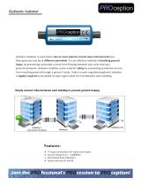
Galvanic Isolation Transformer
The galvanic isolation transformer can be delivered for one- or two-phase connection. When connecting a Smart-UPS DP
and galvanic isolation transformer, the AC bus and the wires for the thermo switch must be mounted. Please follow the
instructions below.
Note:
If the cables in the galvanic isolation transformer have 4 wires, the wire marked no. 3 must be cut off.
Galvanic Isolation Transformer Connections
The AC bus from the galvanic isolation transformer must be mounted.
Note:
If the galvanic isolation module is installed it must be secured so that the neutral is grounded according to local regulations.
This is done in the galvanic isolation transformer with a wire between terminal 5 (PE) and 9 (neutral).
This wire is already mounted from the factory. If the Smart-UPS DP has to be grounded to a separate EDP earth, this is done
to terminal 9, after having removed the wire between terminals 5 and 9.
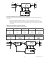
Standard System With Isolating Transformer (230 V)
System Mains Fuse*
(Fm)
Input Cable
Transformer
Input Cable UPS Output Cable UPS
4kV 25A 3x6 mm² 3x6 mm² 3x4 mm²
6kV 40A 3x10 mm² 3x10 mm² 3x10 mm²
8kV 50A 3x16 mm² 3x16 mm² 3x10 mm²
10kV 63A 3x16 mm² 3x16 mm² 3x16 mm²
*Din gl Types
UPS
EPOCOM
PORT
NL NL
INPUT CABLE UPS
LOAD
L
N
OUTPUT CABLE UPS
MAINS
L
N
PE
Input
Cable Tr.
Iso.Tr
.
L
N
Tr. Sw. cable
L
N
Fm

990-1007A, Revision 2 9/99
9
Standard System With Isolating Transformer (400 V)
System Mains Fuse*
(Fm)
Input Cable
Transformer
Input Cable UPS Output Cable
UPS
4kV 16A 3x2.5mm² 3x6mm² 3x4 mm²
6kV 25A 3x6 mm² 3x16 mm² 3x10 mm²
8kV 32A 3x10 mm² 3x16 mm² 3x10 mm²
10kV 40A 3x10 mm² 3x16 mm² 3x16 mm²
*Din gl Types
UPS
EPOCOM
PORT
NL NL
INPUT CABLE UPS
LOAD
L
N
OUTPUT CABLE UPS
MAINS
L1
L2
PE
Input
Cable Tr.
Iso.Tr
.
L1
L2
Tr. Sw. cable
L
N
Fm
Fm

990-1007A, Revision 2 9/99 10
External Service Bypass Panel (SBP)
Note:
The Smart-UPS DP must only be connected by service bypass panels (SBPs) manufactured by APC. If SBPs other than those
manufactured by APC are used, the UPS system may be damaged and the warranty given by APC is repealed.
During the installation of the service bypass panel, you must attach a ferrite bead on the signal cable to ensure regulatory
compliance. A ferrite bead and its installation instructions are included in the literature kit.
The external service bypass panel isolates the system so that service can be carried out safely without any interruption to
the load.
WARNING:
Be careful when operating the external service bypass panel. Follow the operating procedure described below carefully.
All pluggable cables between the Smart-UPS DP and the SBP should be disconnected or should only be connected while the
SBP is in the Bypass position.
When the SBP is switched from “Normal” to “Bypass” the Smart-UPS DP no longer regulates and filters the input voltage.
Service Bypass Panel SBP Mounting Holes
System Input
UPS SERVICE BYPASS
SBP100E
Refer to U ser G uide
for operation instru ctions
System Output
Q001
Q002
H002
S002
Normal
Bypass
Only operate Q002
when H002 is ON
Press and hold
S002 to request
ope ration of Q00 2
UPS Output
This panel has two
sources of power.
UPS Input
This panel has tw o
sou rces of pow er.
! !
X001
SYSTEM
INPUT
X010
B
C
A
X002
UPS INPUT
X
003
UPS OUTPUT
X
004
SYSTEM
OUTPUT
Key
SUDP001 SUDP002
A = 240 mm 270 mm
B = 240 mm 330 mm
C = 4 x ø 6.5 mm
Service Bypass Panel Connections
Standard system with Service Bypass Panel (SBP)
System Mains Fuse*(Fm) Input Cable SBP Input Cable UPS
4kV 25A 3x6 mm² 3x6 mm²
6kV 40A 3x10 mm² 3x10 mm²
8kV 50A 3x16 mm² 3x16 mm²
10kV 63A 3x16 mm² 3x16 mm²
*Din gl Types
System Output Cable UPS Output Fuse SBP (Fo) Output Cable SBP
4kV 3x4 mm² 20A 3x4 mm²
6kV 3x10 mm² 32A 3x10 mm²
8kV 3x10 mm² 40A 3x10 mm²
10kV 3x16 mm² 50A 3x16 mm²

990-1007A, Revision 2 9/99
11
UPS
NL NL
INPUT
CABLE
SBP
MAINS
L
N
PE
LOAD
L
N
OUTPUT
CABLE
SBP
SBP
L
N
L
N
Input
cable
UPS
Output
cable
UPS
Fm Fo
1 2 3 4
MBS CONTROL
SBP
CABLE
X010
1 2 3 4
External Service Bypass Panel and Galvanic Isolation Transformer
If both the external service bypass panel and the galvanic isolation transformer are installed, the following connections
must be made:
• If the cables in the galvanic isolation transformer have 4 wires, the wire marked no. 3 must be cut off.
• If Smart-UPS DP has an ohm load, then it is necessary to ensure the system with 20A. In this case, an external
manual bypass switch which is supplied with a 32A CEE plug, should be used. The switch can ensure both 20A
and 32A fuses.
SBP and Galvanic Isolation Transformer Connections
Standard System With Isolating Transformer (230 V) And SBP
System Mains Fuse*
(Fm)
Input Cable
Transformer
Input Cable SBP Input Cable UPS
4kV 25A 3x6 mm² 3x6 mm² 3x6 mm²
6kV 40A 3x10 mm² 3x10 mm² 3x10 mm²
8kV 50A 3x16 mm² 3x16 mm² 3x16 mm²
10kV 63A 3x16 mm² 3x16 mm² 3x16 mm²
*Din gl Types
System Output Cable UPS Output Fuse SBP (Fo) Output Cable SBP
4kV 3x4 mm² 20A 3x4 mm²
6kV 3x10 mm² 32A 3x10 mm²
8kV 3x10 mm² 40A 3x10 mm²
10kV 3x16 mm² 50A 3x16 mm²
MAINS
L
N
PE
Input
Cable Tr.
Iso.Tr
.
L
N
Tr. Sw. cable
L
N
UPS
NL NL
INPUT
CABLE
SBP
LOAD
L
N
OUTPUT
CABLE
SBP
SBP
L
N
L
N
Input
cable
UPS
Output
cable
UPS
1 2 3 4
MBS CONTROL
SBP
CABLE
X010
1 2 3 4

990-1007A, Revision 2 9/99 12
Standard System With Isolating Transformer (400 V) And SBP
System Mains Fuse*
(Fm)
Input Cable
Transformer
Input Cable UPS Output Cable
UPS
4kV 16A 3x2.5mm² 3x6mm² 3x6 mm²
6kV 25A 3x6 mm² 3x16 mm² 3x10 mm²
8kV 32A 3x10 mm² 3x16 mm² 3x10 mm²
10kV 40A 3x10 mm² 3x16 mm² 3x16 mm²
*Din gl Types
System Output Cable UPS Output Fuse SBP (Fo) Output Cable SBP
4kV 3x4 mm² 20A 3x4 mm²
6kV 3x10 mm² 32A 3x10 mm²
8kV 3x10 mm² 40A 3x10 mm²
10kV 3x16 mm² 50A 3x16 mm²
LOADMAINS
L1
L2
PE
Input
Cable Tr.
Iso.Tr
.
L1
L2
Tr. Sw. cable
L
N
UPS
NL NL
INPUT
CABLE
SBP
L
N
OUTPUT
CABLE
SBP
SBP
L
N
L
N
Input
cable
UPS
Output
cable
UPS
Fm
Fo
Fm
1 2 3 4
MBS CONTROL
SBP
CABLE
X010
1 2 3 4
External Run Battery Cabinet
Note:
You must attach a ferrite bead to the signal cable of the extended run battery cabinet to ensure regulatory compliance. A ferrite
bead and its installation instructions are included in the literature kit.
For longer uninterrupted power during UPS on-battery operation, connect an extended run battery cabinet to the
Smart-UPS DP. All connection diagrams show the UPS with an extended run battery cabinet already connected.
Detail of Smart-UPS DP with an Extended Run Battery Cabinet
UPS
EPOCOM
PORT
NL NL
DC
384V
Belt
Temp.
sensor
++
DC
cable
Temp.
sensor
cable
Ext.
DC
Ext.
Batt
Temp.
UPS
output
UPS
input
MBS control
Ext. Tr.
Th.
Sw.

990-1007A, Revision 2 9/99
13
Operating Instructions
Switching On
F
0
0
1
M
a
i
n
s
Switch on the mains fuse on the rear of the UPS. The Smart-UPS DP will perform a self-check ending with
the LED display showing red/yellow/green, meaning that the unit is functioning properly. The unit performs
a self-test automatically when turned on, and every two weeks thereafter
.
Switch the 1/0 switch on the front of the Smart-UPS to 1 (up). The acoustic alarm will give a short beep
when output power is available.
Note:
Whenever the UPS is turned on and utility voltage is present, the charger maintains battery charge.
Switching Off
Switching off the Smart-UPS DP must be done in the following way:
• Switch the on/off switch on the front to 0 (down).
• Switch off (down) the mains fuse on the rear.
• Switch off the main supply.
Setting the Voltage
If the AC power mains voltage is not 230 V (the factory-set default for the UPS), use the PowerChute
®
power management
software to set it to the correct voltage. This must be done with no load connected to the UPS.
External Service Bypass Panel Operation
The external service bypass panel (SBP) isolates the Smart-UPS DP so service can be carried out safely without any
interruption to the load.
WARNING:
The Smart-UPS DP must only be connected by service bypass panels (SBPs) manufactured by APC. If SBPs other than those
manufactured by APC are used, the UPS system may be damaged and the warranty given by APC is repealed.
When the SBP is switched from “Normal” to “Bypass” the output voltage is no longer adjusted or controlled by the
Smart-UPS DP.
Before operating the SBP, check that the Smart-UPS DP is running in normal operation. When S002 is pushed, H002 must go
on within 1 second - if not, release S002 immediately- bypass mains is outside tolerances and the SBP cannot be operated.
Q001:
Q002:
0 :
I :
Normal :
Bypass:
Supply voltage to Smart-UPS DP is OFF.
Supply voltage to Smart-UPS DP is ON.
The Smart-UPS DP is running in normal operation.
The electrical load is supplied directly from the Smart-
UPS DP.
The electrical load is supplied via the bypass switch
from the mains.
Note:
Ensure that the UPS is operating on-line (Normal mode) before switching to the Bypass mode.
How to Switch From Normal to Bypass Mode
1. Press and hold the S002 switch and, within one (1) second turn the Q002 switch to the Bypass position.
2. Turn the Q001 switch to the “0” position. The UPS can now be shut down or serviced.
How to Return to Normal Mode
1. Turn the Q001 switch to the “I” position.
2. Turn the Smart-UPS DP on by switching the front panel switch from the “0” to the “I” position.
3. Push and hold the S002 switch and, within one (1) second turn the Q002 switch to the Normal position.

990-1007A, Revision 2 9/99 14
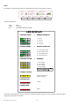
LEDs
The LED bar on the front of the unit gives information by means of color and size of the bar.
[ MUTE ]
Battery Oper.
Check Battery
Green
Yellow
Normal Oper.
Recharging Batt.
[ 100 % ][ 50 % ]
[ 25 % ]
[ 75 % ]
Overload
Red
Bypass / Failure
The general meaning is:
Green = Okay.
Yellow = Okay, but...
Red = DANGER!! Might lose output.
CONSTANT GREEN
FLASHING GREEN
CONSTANT YELLOW
FLASHING YELLOW
CONSTANT RED
FLASHING RED
= NORMAL OPERATION
= CHARGING
= BATTERY OPERATION
0 - 25% load
0 - 25% recharged
25 - 50% load
25 - 50% recharged
50 - 75% load
50 - 75% recharged
75 - 100% load
75 - 100% recharged
Battery is wearing out and
needs to be changed
Overload
Bypass
100 - 75% remaining energy
75 - 50% remaining energy
50 - 25% remaining energy
25 - 0% remaining energy
LED DISPLAY
An alarm will sound when the UPS goes into battery operation, bypass operation, or fault conditions. (The alarm can be
stopped by pressing the mute button.)
Page is loading ...
Page is loading ...
Page is loading ...
Page is loading ...
-
 1
1
-
 2
2
-
 3
3
-
 4
4
-
 5
5
-
 6
6
-
 7
7
-
 8
8
-
 9
9
-
 10
10
-
 11
11
-
 12
12
-
 13
13
-
 14
14
-
 15
15
-
 16
16
-
 17
17
-
 18
18
-
 19
19
-
 20
20
-
 21
21
-
 22
22
-
 23
23
-
 24
24


American Power Conversion SUDP10000I User manual
- Type
- User manual
Ask a question and I''ll find the answer in the document
Finding information in a document is now easier with AI
Related papers
-
American Power Conversion 420/620 User manual
-
-
-
-
Schneider Electric PowerStack 250 VA, 450 VA, 120 V User manual
-
-
-
-
-
Allen-Bradley Bulletin 1609 User manual
Other documents
-
Minuteman ED6000RMXFMR User manual
-
 Hanwha Vision SBP-150CMI Ceiling Mount Operating instructions
-
 PROception PROGALISOL11 Operating instructions
-
APC SUDP001 Datasheet
-
-
APC BP1400 Datasheet
-
APC 1400 User manual
-
-
-
Hanwha Techwin SBP-302CMB User manual

